Wideband mindeD wrote:Please explain why. None of those reasons explain why, and we spoke of the inertial moments being damped/boosted by applying current at the right times.
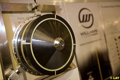
Have you actually ever seen the physical size of a complete flywheel unit such as these??


Now imagine this attached to a turbo CHRA, sitting above the gearbox and behind the engine. This might give you a sense of the issues in placing such a hybrid flywheel assembly physically onto the CHRA of the turbo. Some of the challenges and my thoughts are detailed below:
1: Due to the FIA regulation requirements, the weight of the flywheel assembly will be lifted in the chassis and at a higher CoG than is optimal;
2: The forces involved will require greatly increased support structures, resulting in an increase in weight, size and complexity. Also, there will be substantial increases in the CHRA for support structures, increasing its complexity, size and weight which will require greater cooling and lubrication capacity. This all negatively affects the CoG of the vehicle both in terms of height in the chassis and front to rear weight distribution as well as affecting packaging requirements;
3: Supporting the flywheel on the same shaft running through of the CHRA as the compressor and turbine wheel will increases the mass substantially over currently employed systems. A current CHRA shaft is significantly under the size of shaft and bearings employed in the Williams flywheel system seen above. The shaft will have to increase in diameter as will the bearings need an increase in size and ability to support a large increase in mass, vibration and possibly heat associated with supporting these extra structures.
4: Most importantly the shaft will have to increase in
LENGTH to accommodate the flywheel system which in turn requires a corresponding increase in stiffness to prevent flexing, which then requires greater diameter, heavier shaft and bearing package(s) as well as physically larger packaging and increased lubrication and cooling. All these increases dramatically and negatively affect drag in the system, increase the moment of inertia of the various components of the assembly when completed and even with the electrical assistance, increases in drag and inertia/weight of the package require greater energy inputs then would otherwise be the case. Heat, vibration and harmonics all require large increases in the supporting structures to maintain serviceability, longevity and reliability;
5: So reliability then becomes the next issue as per the above. Either you have a large weight/diameter flywheel spinning under the RPM of the compressor which you need to gear down or a small flywheel spinning at 120,000rpm+. The harmonics and forces involves mean the assembly will have to be extremely rigid to survive, increasing packing weigh and size further so impacting CoG and possibly even having a detrimental effect on aero bodywork. Also, the flywheel, support shaft, bearings etc will be subjected high heat loadings from the exhaust proximity at around 1,000 degrees as well as the vibrations of the engine revving to 15,000rpm and the gearbox harmonics and vibrations as well as the associated shock loadings from the suspension as the engine and gearbox casing to which it is attached are stressed members of the vehicle to which the suspension components connect to, all of which will be in very close proximity in a covered/enclosed environment.
6: These flywheel systems typically use various types of gearing systems to reduce the RPM at which the flywheel spins at. As an example, a 12:1 gearing mechanism spinning a heavier flywheel at 10,000rpm vs. a 1:1 direct drive ratio where it would see a lighter flywheel spin at 120,000rpm. Having either system in such close proximity to high vibration, high temperature environment is not a recipe for longevity. This aside from the dangers of having this so close to a drivers head or at head height for other drivers in an impact. Hence the need to suitable, strong casing and enclosures.
7: The speed at which the turbo must react to transient throttle changes is incredibly fast. Attaching a flywheel and then trying to slow and speed up that weight will be either a massive trade off of energy required and/or produced as well as requiring a support structure to overcome the torsional forces involved. If you have ever seen an engine flywheel fail at high RPM (9,000rpm+) then imagine something letting go at 10,000rpm or even 120,000rpm right behind the driver head. The containment cell must be very substantive as per the pictures below.

Given the extremely high forces involved and that containing and controlling them requires specific systems which are bulky, heaving and require support, having this high and towards the rear of the chassis is definitely suboptimal.
Wideband mindeD wrote:There are already turbo CHRA's that incorporate an electric motor/generator that can produce electricity and then recover that to keep the compressor spinning. So all that is needed is a storage device. Link? That would be awesome to read up on.
I will look for some of the documentation that I have laying around on a hard drive somewhere.

Wideband mindeD wrote:Completely non-applicable to what I proposed.
I know, but what you proposed whilst sounding good in theory carries with it to many primary and secondary detrimental effects and requires further solutions to overcome basic engineering deficiencies. The easiest solution is usually the best, why build weaknesses into a system when you can get a greater benefit using a better design.
Wideband mindeD wrote:Once again, I am not talking about a seperate KERS unit or storage, just a MMC/electromagnetic coil flywheel as a means of applying and removing energy from the prop shaft while in the same rotational axis. The weight would be less than 1 kilogram, and depending on where you mount the turbo, the COG argument is not really admissable.
It is totally admissible as while an MMC or carbon based flywheel may in and of itself only weigh 1kg, the support and containment structure will be substantially greater.
This weighs more than 1kg.

Also you forgot to factor in that the shaft and bearings to support the extra 1kg, which is a multiple greater than what current CHRA systems are designed to carry, would be required to be substantially stronger and therefore heavier which increases overall inertia and drag of the system as well as introduces unwanted harmonics and vibrations. a compressor/turbine assembly in a turbo spinning at 120,000rpm is extremely finely balanced, and at under 500grms such as the examples of the new Borg Warner EFR Gamma-Ti turbines are approximately half the weight of traditional Inconel or other nickel alloy turbines, then you are going to increase that mass by 3 or 4 times. Weigh is absolutely the whole issue. Look at the huge investments made by various companies in metallurgy to reduce the weight of turbines while maintaining heat resistance. Low mass/low inertia is the holy grail of turbo technology for a myriad of reasons. VGT, twin scroll housings and other technologies have all been used to increase response and efficiency.
Wideband mindeD wrote:Maybe they just dont need that fine of a control over the prop-shaft speed?
You can try and keep the compressor spinning and bleed off excess pressure if that’s what you are alluding to but again this brings a number of other detrimental effects. Fine control and resolution over shaft speed and the ability to accelerate or decelerate quickly the CHRA assembly as required is exactly what’s needed. That’s why manufacturers are chasing the inbuilt electric motor option. It is light, and helps to quickly accelerate the assembly when needed, while assisting in controlling shaft RPM and energy recovery.
Never approach a Bull from the front, a Horse from the back, or an Idiot from any direction


