[youtube]http://www.youtube.com/watch?v=mJybR-uWTUc[/youtube]
Due to the complexity of the system, its creator, Diego Cano Zuriguel, decided to wait to post the entire system up be able to explain in detail the operation of all their components. The result is this 15 minute video that is will try to expand on this article.
(Right click/View image) for view images to 1280x720

What is the funtion of the MM-Duct?
The MM-Duct function is to collect one or more flows of air, of one or more inlets of the car and eject it in different areas of the same if it is in straights, or in braking, cornering left, right curves, etc..
What are the benefits?
The ability to vary any aerodynamic zone the car according to this perform any maneuvers.
Is it legal?
No moving parts, not used the DRS, and is not operated by the pilot, therefore, should be completely legal for the 2013 season.
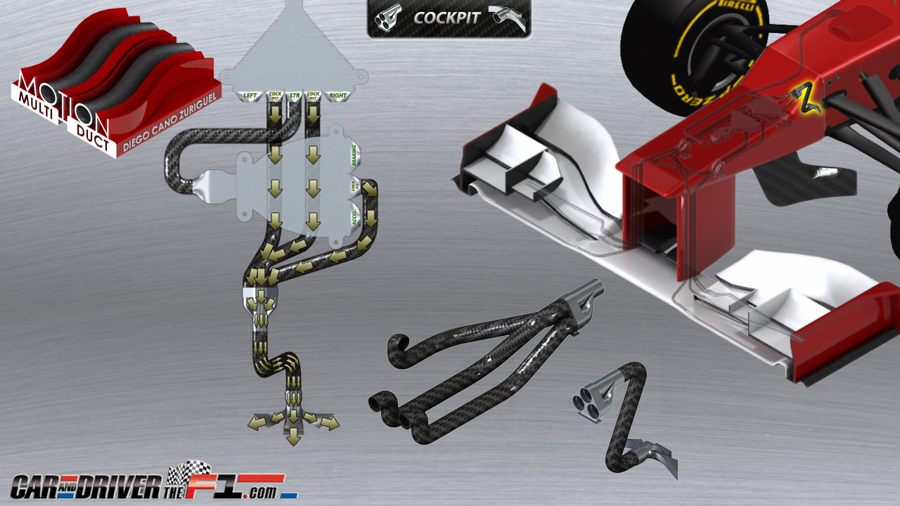
MM-DUCT OPERATION
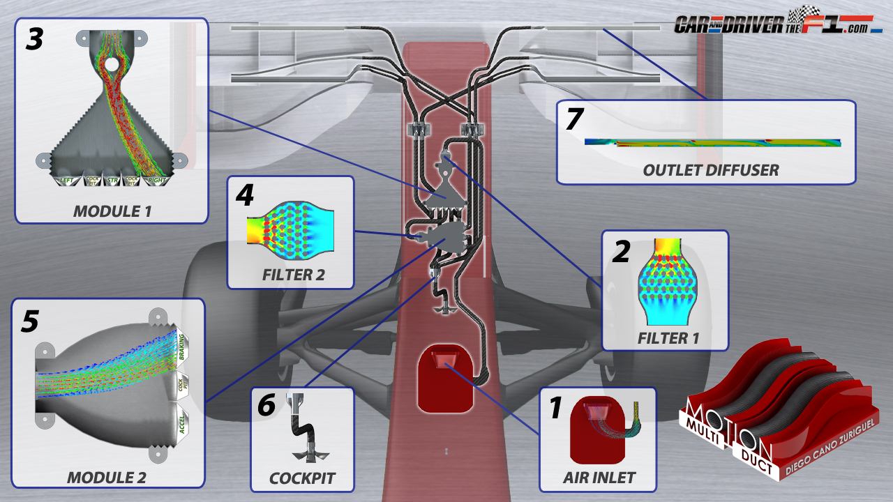
1. AIR INLET
- From any inlet or inlets of the car, is collected airflow.
- This airflow is channeled to the entrance of system through a duct and reaches the first component, the "Filter 1".

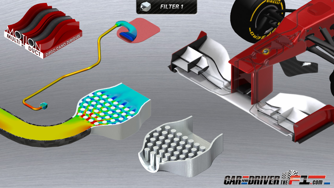
2. FILTER 1
- The airflow is reorganized by this component, slows down and creates a uniform exit in velocity, pressure and direction to
prepare for entry to the next component, the "Module 1". (In this way we eliminate any problem of wind on track or turbulences of other cars, the main problem of the previous system, the W-Duct).
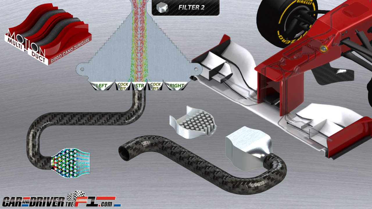
3. MODULE 1
- The uniform and centred airflow that reaches to the "Module 1" is deflected proportionally in the opposite direction of
lateral displacement the car (really deviates the car,and not the airflow).
- Then, to prevent turbulences, and that the airflow sticking to the walls of the module (by a known aerodynamic effect), for improving accuracy and reducing the dimensions of the module, this air flow is deflected in the opposite direction.
- To the end of "Module 1" there are 5 outlets :
- 1 Outlet for straights.
- 1 Outlet for left corners.
- 1 Outlet for right corners.
- 2 Intermediate outlets to the cockpit.
- The airflow enters the corresponding outlet in proportional manner and without mingling thanks to two intermediate outputs that send extra airflow to the cockpit.
- The airflow that entering in the outlets for left and right corners is sent to the front wing.
- The airflow that entering in the straights output is sent through a conduit to the "Filter 2".

4. FILTER 2
- In the same way that "Filter 1", this component again rearranges the airflow inlet to prepare it for the next component, the "Module 2".
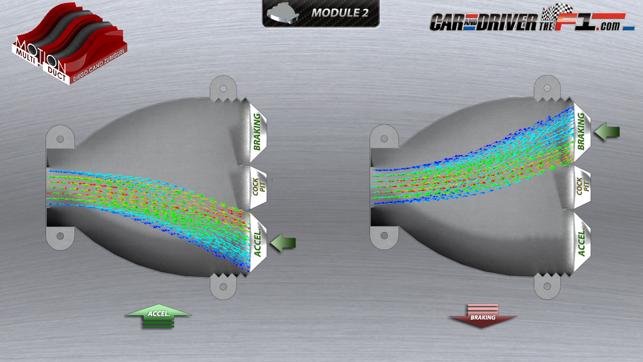
5. MODULE 2
- The uniform and centering airflow that reaches to the "Module 2" is deflected proportionally to the longitudinal displacement the car. In accelerations airflow is deflected backwards, and in braking, because of fast deceleration and the design of this module, is deflected forward.
- To the end of "Module 2" there are 3 outlets:
- 1 Outlet for acceleration in straights
- 1 Outlet for braking in straights.
- 1 Intermediate output to cockpit.
- The airflow enters the corresponding output in proportional manner and without mingling thanks the intermediate output that sent extra airflow to the cockpit.
- The airflow that entering in the outputs for acceleration and braking in straights, in this case is sent to the front wing.
6. COCKPIT
- The airflow of the 3 outputs to the cockpit (two from "Module 1" and one from the "Module 2") are sent through ducts to a special piece where they are concentrated without mingling.
- From this piece are channeled by a triple duct.
- And finally are expanded and expelled into the cockpit separately through a diffuser designed for this purpose.
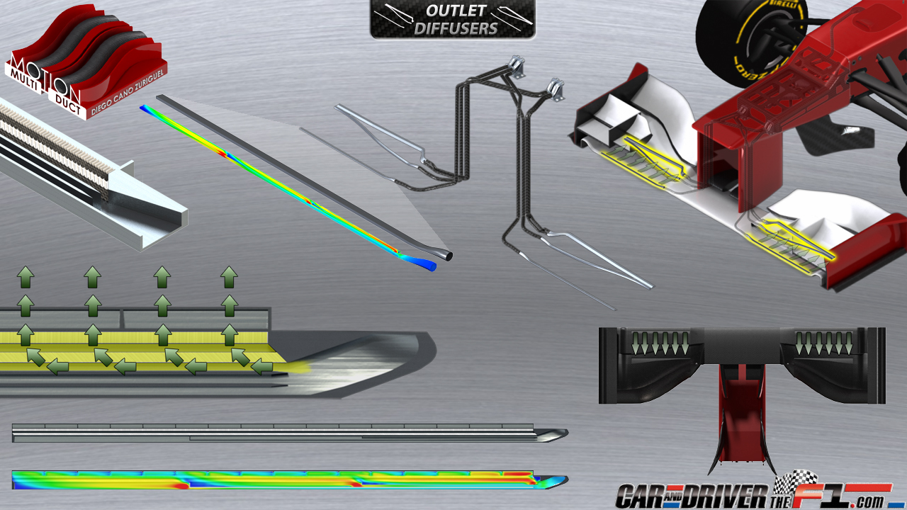
7. OUTLET DIFFUSERS
- The airflow of outputs for left and right corners of the "Module 1" and outputs for acceleration and braking in straights of the "Module 2" are sent through a series of ducts up to the "Outlet diffusers", located in this case in the front wing:
The outlet for left corners is sent through a duct up the "Outlet diffuser for left corners"
The outlet for right corners is sent through another duct up the "Outlet diffuser for right corners"
The outlet for acceleration in straights is split into two equal parts and sent to two "Outlet diffusers for acceleration in straights"
The outlet for braking in straights also is split into two equal parts and sent to two "Outlet diffusers for braking in straights"
- The airflow reaches each these "Outlet diffusers" by one of its sides and through a series of channels and porous materials manages to divert its direction 90 degrees and expands in the entire length of the diffuser before ejecting it into the given zone.
- These "Outlet diffusers' create aerodynamic effects similar to the "boundary layer blowers" used in aeronautics.
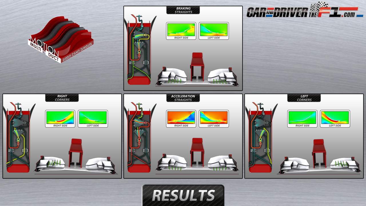
RESULTS
"Acceleration in straights"
- The two "Outlet diffusers for acceleration in straights" expel the airflow under the front wing toward the asphalt (near the leading edge of the second wing, toward the trailing edge of the first wing), breaking the boundary layer and creating a effect similar to F-Duct, subtracting downforce and at the same time the drag, allowing to car gain some top speed.
"Braking in straights"
- The two "Outlet diffusers for braking in straights" expel airflow under the surface of the front wing (on the intrados of the first wing towards its trailing edge), accelerating the airflow velocity under the first wing and increasing downforce under braking,reducing slightly the braking distance.
"Left corners"
- The "Outlet diffuser for left corners" expels airflow under the surface of the left side of the front wing (on the intrados of the second wing left towards its trailing edge) increasing airflow speed under side left front wing and increasing the downforce in this area. According to the flexibility of the front wing, one can reduce the distance to the ground in this side, since the left front wing is distanced considerably of ground in left corners and vice versa.
"Right corners"
- The "Outlet diffuser for right corners" behaves like that the "Outlet diffuser for left corners" but on the right side of the front wing.
OTHERS CONFIGURATIONS
The MM-Duct configuration presented in this article is only one of many possible:
-The system can include, from a unique outlet for acceleration in straights, up to six, be adding to the four standard outlets, one output for braking in left corners and one for braking in right corners, adding 2 additional modules.
-Could work together on front and rear wings, on the diffuser, or any area or aerodinamic surface.
-This system also It can be adapted to many types of vehicles and use multiple simultaneous systems to multiply their effects.
-The length of the MM-Duct support within the nose may be reduced to half by placing the "Module 2" under the "Module 1" (is designed thereby for show better its operation).
In any case, may it would make sense to start by a easier system, with one unique outlet for accelerations in straight, and go slowly adding other options when its operation would safe and efficient.
Although this system can not be tested in the wind tunnel, it can be proved in a completely secure on track, by sending all outlets to the cockpit and finishing the job with the CFD, using the data adquired for several sensors in each of these outputs.
Still is necessary much work to correlate all of these components with the aerodynamic of a specific car, but maybe this concept or any of its components could be interesting for some teams. It is also certain that would necessary solve many problems that would arise in its development, but certainly for its developer would this the most stimulating part of all.
caranddriverthef1 article:
http://www.caranddriverthef1.com/formul ... alle-video