BAR serrated gurneys

Here are our CFD links and discussions about aerodynamics, suspension, driver safety and tyres. Please stick to F1 on this forum.
scarbs
scarbs
393
Joined: 08 Oct 2003, 09:47
Location: Hertfordshire, UK

BAR serrated gurneys

Post

At the recent Silverstone test BAR tried Serrated Gurneys on their rear wings with larger teeth at a wider pitch on a gurney depth of around 20mm

http://scarbsf1.com/silv_test0204/BAR_serrated.htm
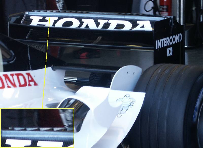
Image

seymour
seymour
0
Joined: 19 Feb 2004, 00:15
Location: pennsylvania

Great picture

Post

This is a really great picture, but I think we're seeing something totally different here. I believe a gurney flap is placed perpindicular to the flow.

To me, this actually looks like a lot of vertical elements between the upper and lower elements of the rear wing. Notice also, that they seem to be missing from the middle of the wing.

I don't know though. The longer I look at it, the more I think it could be either one, but it just seems that if its a gurney flap, then it wasn't manufactured very well.

scarbs
scarbs
393
Joined: 08 Oct 2003, 09:47
Location: Hertfordshire, UK

Post

I beleive it is a gurney, but the angle of the upright "serated" section to the wing is not perpendicular, but more accute.

seymour
seymour
0
Joined: 19 Feb 2004, 00:15
Location: pennsylvania

More reasons

Post

Okay, I don't mean to beat a dead horse, but if you look at the complete picture, the left side of the picture, and the right side of the rear wing, you can see clearly see the top of the rear wing end plate. If you follow that back, until the intersection of the top rear wing element, you see that the line is in front of the "teeth". It is at a higher angle so the light reflects more directly from it. You can follow that line all the way to the other side of the wing where there appears to be a fairly sizeable slot between the top element, and the element I think is below it in the rear wing end plate.

I don't know, I guess, I might be pursuaded I'm seeing this all wrong, but gurney strips are supposed to be 90 degrees, and this would be much more acute. Also, the vertical strips seem to have more in common with the inner end plates BAR has tested and ran in Australia, perhaps indicating a natural progression in thought.

Of course the whole thing is basically moot if its not deemed race worthy.

marcush.
marcush.
0

Post

may it be possible ,that bar tries to divide the upwash of the rearwing into two separate flows,maybe vortices?the middle section seems between the
forwrd elemnt and the main element seem to be closed ,possibly a wedge forming under the upper element as a divider the outer visible longitudinal strakes only there to distribute the flow more evenly across the two tunnels?
just a thought....

User avatar
NickT
2
Joined: 24 Sep 2003, 12:47
Location: Edinburgh, UK

Post

Sorry Scarbs I don't think this is a serated gurney flap. They tend to be set perpendicular to the trailing edge of the aerofoil in a similar manner to a conventional gurney flap and a lot smaller.

I think it is more likely to be control of the up wash from the underside of the upper aerofoil, like marcush suggested. If you look closely it looks like the trailing edges of both elements are connected. Vortex control?
NickT

Monstrobolaxa
Monstrobolaxa
1
Joined: 28 Dec 2002, 23:36
Location: Covilhã, Portugal (and sometimes in Évora)

Post

Well I kind of agree with the last 2 posts

seymour
seymour
0
Joined: 19 Feb 2004, 00:15
Location: pennsylvania

I want validation too

Post

How come you didn't agree with any of my posts Monstro?

Still its nice to see some validation.

The only application of the vertical elements would be to prevent transverse flow along the wing, possibly in an effort to optimize efficiency across the whole length of the wing without resorting to the three dimensional wings other teams have resorted to.

Guest
Guest
0

Post

These are not serrated gurney flaps but mini vertical plates (functioning in a way akin to wing endplates) - there is a post somewhere on this website which shows the back of a Rally Car which has about 10(?) vertical plates lengthways along the wing. It reduces transverse flow along the length of the wing and the amount of horseshoe vorticies at the wingtips- thus reduced drag and improved lift coefficients.

Not sure how relevant the 2 vs 3 wing argument is but you could argue that the reduced no. of elements (2) makes it harder to control flow seperation and transverse flow at high attack angles - e.g. for Monaco!

;-)

Reca
Reca
93
Joined: 21 Dec 2003, 18:22
Location: Monza, Italy

Post

Aerodynamics in F1 is driven by rules :

3.10.3 :
Any bodywork more than 150mm behind the rear wheel centre line which is more than 300mm above the reference plane, and between 75mm and 480mm from the car centre line, must lie in one of two areas when viewed from the side of the car :
[...]
The upper area is situated from 600mm to 800mm above the reference plane, and from 150mm to 500mm behind the rear wheel centre line. When viewed from the side of the car, no longitudinal cross section may have more than two closed sections in the upper area. Furthermore, the distance between adjacent sections at any longitudinal plane must not exceed 15mm at their closest position.[...]

The last row has been added this year and is aimed to avoid the use of a “biplane” configuration of the rear wing upper elements, forcing to adopt the “main element + flap” design.
As you can see in the pic the gap between the trailing edges of the two elements looks larger than 15 mm.
But, a fin connecting upper and lower element would make them to count as a single closed section. The fin however can’t be vertical because then the problem would be in the longitudinal sections between two vertical plates, so the fins probably have an inclination/curvature, something like this (frontal view) : |\\\\ ////| .
As you can see this way the fins would connect the two elements in any longitudinal section. At the end, since the same rule is valid only out of the central 150 mm., that explains why in the central part the fins aren’t present.
The next most logical step is then to have a three element design just as last year (main + flap & upper element) but with upper element and flap counting as one since are connected by the fins. Then what remains to be seen is how the presence of the fins modifies the behaviour of the wing but I think that it was designed in a first time simply to have three wing elements as last year or maybe just a biplane. Clever design undoubtedly.

dumrick
dumrick
0
Joined: 19 Jan 2004, 13:36
Location: Portugal

Post

Excellent post, Reca. What I was seeing here was a wing configuration that seemed to have been outlawed this year...
That explains it all!!!! :wink:
Let's just wait to see if it works...

marcush.
marcush.
159
Joined: 09 Mar 2004, 16:55

Post

so if this design serves to reduce the count of wing elements,why not bend over a Wingelement to form an extreme S-Shape and have the
fold over end serve as a flap? Voila,one Element ,still a Flap function.
anyone out there to buy that idea?I thought toyota was in desperate need of Downforce... and they have the money to acrually produce this nightmare for the modelmaker....
Another one just for the record:Why not put ducts into the Single element to actually form an interrupted slot ? Ok ,you have to change the whole wing to adjust the downforce but hey, after all it´s only money...

User avatar
joseff
11
Joined: 24 Sep 2002, 11:53

Post

I remember an article from way, way, in the last century (1980's or so, no kidding) about cross-drilling wings to lower their stall speed. Apparently it didn't turn out to be a good idea (well we haven't seen swiss-cheesed airliner flaps yet). Would the CFD gurus here comment on this little bit, though?

Reca
Reca
93
Joined: 21 Dec 2003, 18:22
Location: Monza, Italy

Post

marcush. wrote: so if this design serves to reduce the count of wing elements,why not bend over a Wingelement to form an extreme S-Shape and have the fold over end serve as a flap? Voila,one Element ,still a Flap function.
The point in the main element + flap design is to have two elements with a gap between them.
The S-shaped airfoil not only wouldn’t have a “Flap function” (no gap) but it would also be a quite inefficient airfoil.
marcush. wrote: Another one just for the record:Why not put ducts into the Single element to actually form an interrupted slot ?
In all the longitudinal sections including the duct it would count as two elements.
joseff wrote: I remember an article from way, way, in the last century (1980's or so, no kidding) about cross-drilling wings to lower their stall speed
Are you referring to the control of boundary layer via suction or blowing (active high lift systems requiring holes on the surface of the wing) ?

marcush.
marcush.
159
Joined: 09 Mar 2004, 16:55

Post

I almost feared you did not understand...
I shuld have said c-formed( if you look from the front)
The turn would be quite acute and indeed form a slot.Of course you would still need some form of endplate to stick to the bend.I don´t think it
would be less efficient then.

ducts in the single element wingsection would actually supply slots and provide the same flow patterns as two or three elemenet wings,
the question here is :what is one element and is it allowed to supply more than one flow path over the wing?