2014-2020 Formula One 1.6l V6 turbo engine formula

All that has to do with the power train, gearbox, clutch, fuels and lubricants, etc. Generally the mechanical side of Formula One.
piast9
piast9
20
Joined: 16 Mar 2010, 00:39

Re: Formula One 1.6l V6 turbo engine formula

Post

I hope we won't. At least not from the beginning of the 2014 season. F1 has to be the pinnacle of the motorsport ant it won't be with frozen engines. Secondly, I am sure that under the freeze the manufacturers will be able to apply some "creative" reliability improvements increasing the horsepower as the side-effect so the freeze will be not effective anyway.

User avatar
ringo
230
Joined: 29 Mar 2009, 10:57

Re: Formula One 1.6l V6 turbo engine formula

Post

autogyro wrote:Looks like a torturous route for the exhaust manifold to join the turbine housing.
If it is like that in the car, it will be a devils own job to prevent heat loss from the manifolds.
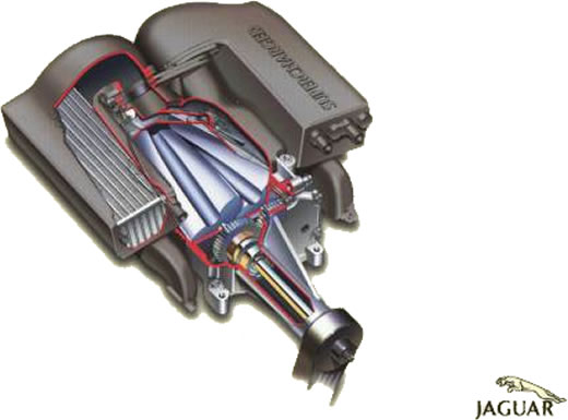
I believe that heat loss component depends on what their going to do with the exhuast manifolds. In terms of materials. Also since the exhuast speed is so high, there may be a very minute difference with the pipe lengths on this design versus a midbank design.
The midbank design probably has a lot drawbacks in terms of flow. It will be interesting to list all differences between the two.
But it's definitely cooler to have the air box over intake manifold that to have the air box sitting over exhuast manifolds in the middle.
Whats the big box on the top, heat exchanger for charge cooling?
It looks like it has split chambers? Air filter in the middle, and air intake tracts from the intercooler on either side?
I would have expected the charge cooler to be in the side pods and to be much bigger.
Well i doubt we are being shown charge coolers here.
If the unit between the compressor and turbine is the MG, that might have a cooling issue as well.
Yes, could be water jacketed. With cooling to a heat exchanger to plumbed back to the engine's cooling system.
For Sure!!

garrett
garrett
12
Joined: 23 May 2012, 21:01

Re: Formula One 1.6l V6 turbo engine formula

Post

You may have two entries to the turbine but you may have only one turbine and one turbine stage.
That´s what the Renault configuration was about, with two vice-versa separate entries for a 3 in 1 exhaust manifold each, notably missing here, although it should provide a far better solution regarding admission and responding behaviour, which should benefit the intended 125.000 revs of the charger, doesn´t it?

User avatar
FW17
169
Joined: 06 Jan 2010, 10:56

Re: Formula One 1.6l V6 turbo engine formula

Post

autogyro wrote: Clever drawing.
When are you going to show us the real one?

I dont think the 10 inch rear wheels will work very well.
I suppose that is because of the crank height difference to the reference plane v8 to v6.
If the 2014 Williams is like that, you have got an awful lot to cram in the side pods.
Love the stove pipe at the back though.
It is almost to scale

Williams drive shaft is steeply inclined.

autogyro
autogyro
53
Joined: 04 Oct 2009, 15:03

Re: Formula One 1.6l V6 turbo engine formula

Post

It is almost to scale

Williams drive shaft is steeply inclined.
Sorry I forgot that.
I remember saying it would have gearbox problems when it first came out with the low profile casing.
So yes it probably is 'almost' to scale.
I would still like to see the real state of play though.
Has Patrick had anything to do with the 2014 car?

User avatar
turbof1
Moderator
Joined: 19 Jul 2012, 21:36
Location: MountDoom CFD Matrix

Re: Formula One 1.6l V6 turbo engine formula

Post

If we take homologating literally, it means development of the engine is allowed inbetween seasons. However, do note engines have to last twice as long and I expect the amount of engines allowed for 1 season, reduced to 4. Meaning even if you were allowed to upgrade, you were stuck with the none-upgraded engine for 5 races of the 20.
#AeroFrodo

User avatar
WhiteBlue
92
Joined: 14 Apr 2008, 20:58
Location: WhiteBlue Country

Re: Formula One 1.6l V6 turbo engine formula

Post

turbof1 wrote:
If we take homologating literally, it means development of the engine is allowed inbetween seasons. However, do note engines have to last twice as long and I expect the amount of engines allowed for 1 season, reduced to 4. Meaning even if you were allowed to upgrade, you were stuck with the none-upgraded engine for 5 races of the 20.
Homologation means indeed that there will be no development - except for failures - to the five engines that will be legal in 2013 or the additional engines a team might be using with penalties.

I agree that it will be likely that there will be a slightly wider scope for 2014 or 2015. So the manufacturers will continue to develop regardless of homologation. In 2015 the number of engines will be reduced to four. The scope for future years is very much a subject of speculations and an exercise in politicking. We will have fun to watch it. :wink:
Formula One's fundamental ethos is about success coming to those with the most ingenious engineering and best .............................. organization, not to those with the biggest budget. (Dave Richards)

CMSMJ1
CMSMJ1
Moderator
Joined: 25 Sep 2007, 10:51
Location: Chesterfield, United Kingdom

Re: Formula One 1.6l V6 turbo engine formula

Post

How is an engine freeze supposed to allow development of the new motors?

This is a bloody crock.

The render of he engine is good to see..but I will wait for the first tests to get that excited about it.
IMPERATOR REX ANGLORUM

User avatar
ringo
230
Joined: 29 Mar 2009, 10:57

Re: Formula One 1.6l V6 turbo engine formula

Post

You know,
there should be some additional structure there to support the turbine. I doubt the exhaust pipes will support the turbo with the generator. It's hard to predict how use of lighter materials will impact on turbine weight, but i feel we are looking at something that you don't want to have cantelvered off the exhuast pipes.
There may be a mounting bracket coming up from the gearbox or from the engine block.

As for turbine performance; i'm expecting big ole trumpet like diffusers on the back of the turbines as exhaust pipes for bigger pressure drop across the turbine.

Does anyone have an image of the Renault concept hanging around, it would be interesting to compare the two engines that we have so far.
For Sure!!

User avatar
markc
4
Joined: 08 Dec 2011, 01:30

Re: Formula One 1.6l V6 turbo engine formula

Post

ringo wrote:... Does anyone have an image of the Renault concept hanging around...
Renault engine here: (racecar-engineering) http://www.racecar-engineering.com/news ... f1-engine/

Very interesting! I had previously assumed the airbox redundant thanks to the turbo (...and being too lazy to check rules), but looking at Merc, Renault and PURE (defunct but still interesting) designs I see it's footprint engine side still there...? Digging further I can see the rules mandate the airbox inlet still above the drivers head... I consider myself schooled in the matter!

Renault have shown more ancillaries attached - airbox direct to turbo, and a box where the airbox would have terminated in the NA engines of old. Merc has the airbox terminating in the NA fashion but feeding the turbo air, with the same structure also handing the pressured air inlet to engine (chambered one assumes). Intercooler in the box? or is that's position mandated ala turbo?

User avatar
WhiteBlue
92
Joined: 14 Apr 2008, 20:58
Location: WhiteBlue Country

Re: Formula One 1.6l V6 turbo engine formula

Post

There is a box defined in the 2014 tech regs where the air intake has to be. But I don't think anybody ever has done a graphic on this to show where it is relative to other elements of the car.
Formula One's fundamental ethos is about success coming to those with the most ingenious engineering and best .............................. organization, not to those with the biggest budget. (Dave Richards)

User avatar
Holm86
247
Joined: 10 Feb 2010, 03:37
Location: Copenhagen, Denmark

Re: Formula One 1.6l V6 turbo engine formula

Post

Holm86 wrote:But why do Mercedes reveal pictures of a complete engine this soon?? To put pressure on FIA to keep the engine regulations for 2014??
So anyone got a clue??

User avatar
matt21
86
Joined: 15 Mar 2010, 13:17

Re: Formula One 1.6l V6 turbo engine formula

Post

markc wrote:
ringo wrote:... Does anyone have an image of the Renault concept hanging around...
Renault engine here: (racecar-engineering) http://www.racecar-engineering.com/news ... f1-engine/

Very interesting! I had previously assumed the airbox redundant thanks to the turbo (...and being too lazy to check rules), but looking at Merc, Renault and PURE (defunct but still interesting) designs I see it's footprint engine side still there...? Digging further I can see the rules mandate the airbox inlet still above the drivers head... I consider myself schooled in the matter!

Renault have shown more ancillaries attached - airbox direct to turbo, and a box where the airbox would have terminated in the NA engines of old. Merc has the airbox terminating in the NA fashion but feeding the turbo air, with the same structure also handing the pressured air inlet to engine (chambered one assumes). Intercooler in the box? or is that's position mandated ala turbo?
The rules mandate a maximum of two air intakes located between the front of the cockpit and 500mm before the rear axle and more than 200mm above the reference plane.

So I would say that the airbox as known today could be given up.

The position of the intercoolers is not mandated and you can use air-to-water-coolers. So why not placing it in the box.
Image

Mika1
Mika1
3
Joined: 16 May 2012, 20:17

Re: Formula One 1.6l V6 turbo engine formula

Post

Holm86 wrote:
Holm86 wrote:But why do Mercedes reveal pictures of a complete engine this soon?? To put pressure on FIA to keep the engine regulations for 2014??
So anyone got a clue??
Of course not, Renault and Mercedes have invested a lot of money in it, FIA can't stop it anymore.
The boss follows me on twitter.

User avatar
Ferraripilot
21
Joined: 28 Jan 2011, 16:36
Location: Atlanta

Re: Formula One 1.6l V6 turbo engine formula

Post

torque ERS/boost control = new traction control?

let's read policy 9.3 carefully shall we:

"No car may be equipped with a system or device which is capable of preventing the driven wheels from spinning under power or of compensating for excessive torque demand by the driver.

Any device or system which notifies the driver of the onset of wheel spin is not permitted. "


The crux of the interpretation in the policy first sentence is preveting spinning under power due to excessive torque, but this is specified by means of preventing the driven wheels. Driven wheels are attached to a gearbox which is attached to the flywheel/engine. Traction control post 2002 was used in such a way that it throttled back the engine which wheels sensors indicated wheelspin was inevitable.


If the new powertrains are built in such a way that electrical energy harvesting can be limited/taylored to a particular circuit and thus released to a different benefit at each circuit, then it would be a function of engine and its inner working and not a specific traction control function, traction control would simply be a by-product of its fundamental function, which essentially means harvesting would be limited so to have torque in areas it may be fully needed when the charge is present, and less charge thus less torque when not needed.

This is similar in a way to the Renault engine designs and 'cold off-throttle blowing' which was inherent to the engine. Renault's off-throttle blowing was simply a positive by-product of the way the engine had to function. Charlie could not simply go to Renault and order they alter their fundamental design, so he simply asked they tone down the amount of ignition timing thrown at the off-throttle blowing mechanism.

This type of V6 energy harvesting and energy application option in no way provides any indicator to a driver which is strictly forbidden per the policy above.

Torque and % of ERS harvesting and ERS application would be pre-determined per circuit. If at a tight circuit with several areas where slip can occur, I would arrange harvesting and ERS application in such a way that it would always be in use, but perhaps keep harvesting at a minimum throughout a particular event so there's not more torque than there is traction. Mind you, the ERS system would always operate at 100%, but harvesting efficiency and its settings would govern the amount of power the ERS power unit would receive which as a matter of function would limit the amount of power able to be produced. This in essence means the powertrain could take on different personalities depending on the circuit and not be controlled during an event. Monza, full tilt, both systems, all around. Monaco, minimum heat harvesting, max power.

With minimum heat harvesting, ERS could be tuned constantly for max power but would simply NOT be able at all to provide max power at times due to minimum harvesting in place simply not being able to keep up, although occasionally max power could be available.

This idea is not a function of altering torque when the torque available is already a sliding scale simply due to energy harvesting and its settings relative to a track in question. Such an idea would be able to work at all circuits and would not be completely beneficial all the way around a circuit unless harvesting could be fine-tuned at each circuit to a point where each team would know an estimate amount of bhp from a harvest that an ERS unit could and should supply at each corner!


further regarding policy 9.3:
9.3 would have to be written to including something regarding energy harvesting and ERS power output to be tuned to provide the maximum benefit of BOTH at all times, no minimal harvesting whilst having max power, no minimum power but max harvesting etc.


with regards to torque control policy

5.5 Torque control :
5.5.1 The only means by which the driver may control acceleration torque to the driven wheels is via a single chassis mounted foot (accelerator) pedal.
5.5.2 Designs which allow specific points along the accelerator pedal travel range to be identified by the driver or assist him to hold a position are not permitted.

5.5.3 The minimum and maximum accelerator pedal travel positions must correspond to the minimum and maximum available torque with the currently selected power unit torque map.


The idea I posted above also fits into this policy guideline, specifically 5.5.3. "Minimum and maximum available torque with the currently selected power unit torque map" in this passage is a very relative term for an engine that would have varying levels of maximum and minimum torque, which are of course based on the amount of energy harvested. In other words, putting ones right foot all the way down always corresponds to the maximum amount of power available at that moment which is relative to the amount of energy harvested. The idea is to tune the harvest to the track, one does not want to have too much harvest for a particular set of corners, but will for another area.


This sounds massively complicated, but tuning a harvest for a circuit could prove benficial, especially if all other powertrains on a circuit are running 100% output on both systems and simply relying on a driver to keep slip from occuring.