Exhaust CFD Comparison

Here are our CFD links and discussions about aerodynamics, suspension, driver safety and tyres. Please stick to F1 on this forum.
User avatar
amouzouris
105
Joined: 14 Feb 2011, 20:21

Exhaust CFD Comparison

Post

I carried out a CFD (Computational Fluid Dynamics) test to compare the two exhaust solutions that were used in the 2012 season, the McLaren style exhaust (1st Picture) and the Red Bull-Sauber Style exhaust (2nd Picture). There has been a lot of discussion about which one of the two solutions is the best and which solution teams will follow in 2013.

I removed the drive shafts, suspension wishbones and pullrod, to keep the test as simple as possible. I did not include a rear wing to reduce the time needed for the test to be carried out. In general, I tried to keep things as simple as possible.

I used a road speed of 55 m/s (200 km/h, 124 mph) and the exhaust speed out of the pipe is at 350 m/s and 850 degrees Celsius.

These are my results:

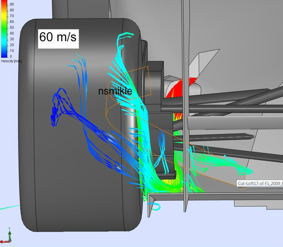
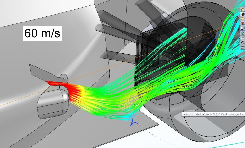
I obviously didn’t manage to get the exhaust plume to bend down to the diffuser in my first iteration of the McLaren style sidepods (1st Picture), but it is definitely possible. This indicates that using this solution it is harder to get the exhaust plume flowing exactly where you want it as opposed to the Red Bull – Sauber style sidepods which I got almost right on the first try (2nd Picture).

Image

Image


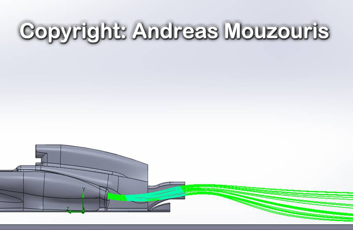
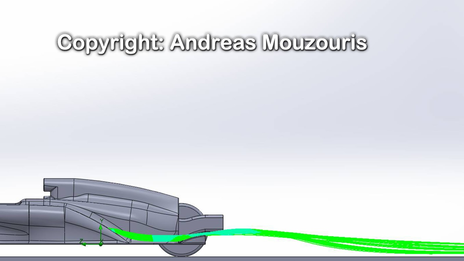
It is believed that using the Red Bull ramp it is easier to get the plume where you want as it is continuously following bodywork to reach the diffuser. My results support this belief, and show a more consistent and predictable flow, which will in turn produce more consistent downforce.

I believe that more teams will follow the trend set by Red Bull and Sauber in 2012 as it is, as I believe, the better solution.

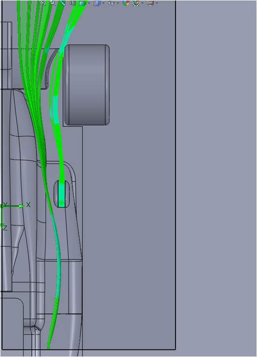
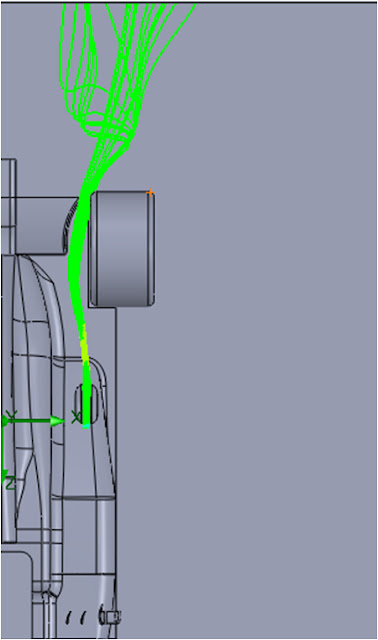
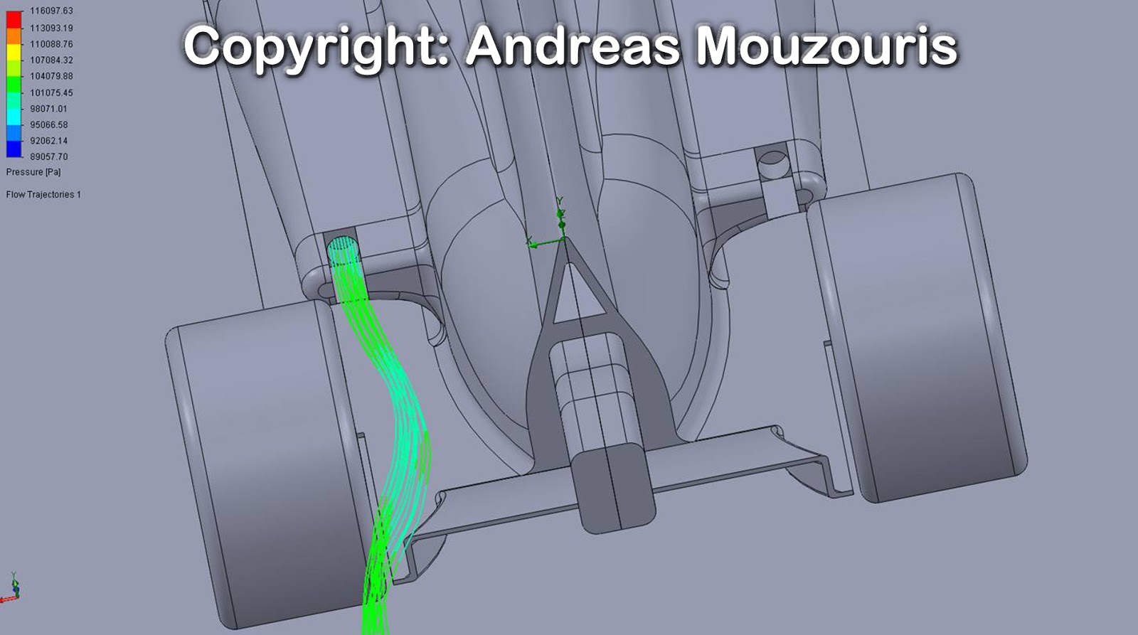
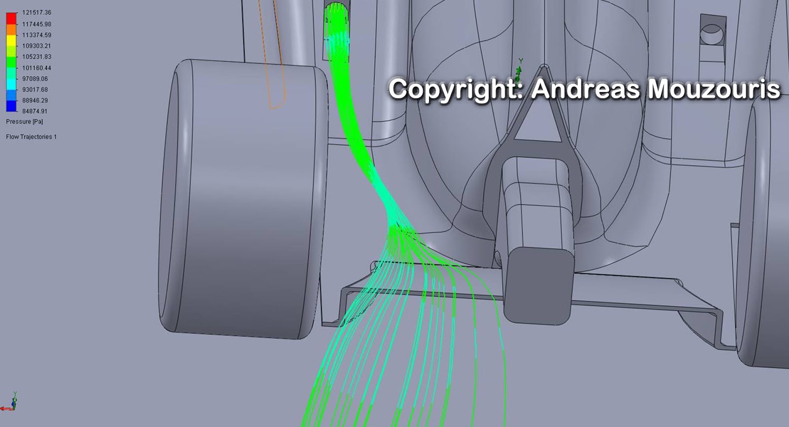
Here are some more shots of the CFD test:

Image

Image

Image


http://technicalf1explained.blogspot.co ... g-cfd.html


PS: Where the left wheel is not visible it is just hidden, it was included in the test.

heho07
heho07
1
Joined: 30 Jun 2012, 22:20

Re: Exhaust CFD Comparison

Post

Is your Mclaren exhaust plume horizontal that exhaust gas can not bent down to diffuser?

wesley123
wesley123
204
Joined: 23 Feb 2008, 17:55

Re: Exhaust CFD Comparison

Post

heho07 wrote:Is your Mclaren exhaust plume horizontal that exhaust gas can not bent down to diffuser?
On the McLaren it is horizontal too, the rules dont allow the exhaust to be bent down, they have to point at least 10 degrees upwards. And this is where the coanda effect kicks in, to help the flow get attached.
"Bite my shiny metal ass" - Bender

mikhak
mikhak
11
Joined: 10 Jul 2006, 02:25
Location: Stockholm

Re: Exhaust CFD Comparison

Post

Nice pictures. Could you explain how you visualised the exhaust plume?

heho07
heho07
1
Joined: 30 Jun 2012, 22:20

Re: Exhaust CFD Comparison

Post

wesley123 wrote:
heho07 wrote:Is your Mclaren exhaust plume horizontal that exhaust gas can not bent down to diffuser?
On the McLaren it is horizontal too, the rules dont allow the exhaust to be bent down, they have to point at least 10 degrees upwards. And this is where the coanda effect kicks in, to help the flow get attached.
Oh my bad.i want to say exhaust duct!
is amouzouris Mclaren exhaust duct flat and horizontal?

User avatar
amouzouris
105
Joined: 14 Feb 2011, 20:21

Re: Exhaust CFD Comparison

Post

heho07 wrote:
wesley123 wrote:
heho07 wrote:Is your Mclaren exhaust plume horizontal that exhaust gas can not bent down to diffuser?
On the McLaren it is horizontal too, the rules dont allow the exhaust to be bent down, they have to point at least 10 degrees upwards. And this is where the coanda effect kicks in, to help the flow get attached.
Oh my bad.i want to say exhaust duct!
is amouzouris Mclaren exhaust duct flat and horizontal?
the ducts are actually facing 10 degrees above the horizontal as require in the regulations

User avatar
amouzouris
105
Joined: 14 Feb 2011, 20:21

Re: Exhaust CFD Comparison

Post

mikhak wrote:Nice pictures. Could you explain how you visualised the exhaust plume?
I didn't fully understand what you mean! But i used Solidworks to model the car and used Solidworks FlowSimulation to solve it! The lines are produced after the car is solved. I hope this answers your question!

timbo
timbo
111
Joined: 22 Oct 2007, 10:14

Re: Exhaust CFD Comparison

Post

Don't think McLaren's model correlate to reality much. Weren't that apparent that the flow from the exhaust is touching the floor ahead of the tyres? I seem to vaguely remember the pictures of burnt floor.
Maybe you can tweak your settings to match that, and then apply results to RedBull also?

User avatar
amouzouris
105
Joined: 14 Feb 2011, 20:21

Re: Exhaust CFD Comparison

Post

timbo wrote:Don't think McLaren's model correlate to reality much. Weren't that apparent that the flow from the exhaust is touching the floor ahead of the tyres? I seem to vaguely remember the pictures of burnt floor.
Maybe you can tweak your settings to match that, and then apply results to RedBull also?
Yes you are right! my model is probably not producing enough downwash and the coanda ramp is a bit too short! with a bit of tweaking i could get the results right! in addition, the Mclaren style sidepod works better at medium speeds than at higher speeds, i tested it at 200 kph. maybe reducing the speed will bend the exhaust down a bit more!

timbo
timbo
111
Joined: 22 Oct 2007, 10:14

Re: Exhaust CFD Comparison

Post

amouzouris wrote:Yes you are right! my model is probably not producing enough downwash and the coanda ramp is a bit too short! with a bit of tweaking i could get the results right! in addition, the Mclaren style sidepod works better at medium speeds than at higher speeds, i tested it at 200 kph. maybe reducing the speed will bend the exhaust down a bit more!
Hey, that could be very interesting thing to look at!
I always thought that Sauber/RBR style exhaust gave much better flow around the diffuser, but maybe McLaren way can actually help to control DF at top speed.

User avatar
PlatinumZealot
558
Joined: 12 Jun 2008, 03:45

Re: Exhaust CFD Comparison

Post

Your model needs some fine tuning. There are some geometrical and physical details you have overlooked. :wink:

This car is based on the "chassis" from a user called "machin" It was heavily bastardised...sidepods wings suspension etc.

Here is my model at 216km/hr:
Image

Image
πŸ–οΈβœŒοΈβ˜οΈπŸ‘€πŸ‘ŒβœοΈπŸŽπŸ†πŸ™

Racing Green in 2028

User avatar
amouzouris
105
Joined: 14 Feb 2011, 20:21

Re: Exhaust CFD Comparison

Post

I carried out this CFD test to help me understand better the effect of vortex generators on the trajectory of the exhaust plume.

This first test was carried out without any VGs:

Image

The second test was carried out with one VG. You can see how the exhaust plume was deflected towards the tire.

Image

The third test was carried out with 2 VGs. The deflection this time was minor, but was made apparent because it was pushed towards the tire and the 'dirty' air behind it which messes up the flow of the exhaust plume.

Image

http://technicalf1explained.blogspot.co ... haust.html

User avatar
slimjim8201
12
Joined: 30 Jul 2006, 06:02

Re: Exhaust CFD Comparison

Post

Interesting topic. I've dabbled in this area as well and agree with n smikle that a more detailed CAD model is necessary. As many on this forum have discovered, obtaining a true to life F1 CAD model is nearly impossible and creating one from scratch can be extremely taxing. Sometimes we get lucky, though. These are results from a Dallara IR07 Indycar I ran a while back.

Image

Image

Image

Image

Image

Image

Image

heho07
heho07
1
Joined: 30 Jun 2012, 22:20

Re: Exhaust CFD Comparison

Post

Great job amouzouris.
Scarb said before that VGs are there to push exhaust plume further down but i can not see vortexes that goes above exhaust plume in your CFD simulation.

User avatar
PlatinumZealot
558
Joined: 12 Jun 2008, 03:45

Re: Exhaust CFD Comparison

Post

slimjim8201 wrote:Interesting topic. I've dabbled in this area as well and agree with n smikle that a more detailed CAD model is necessary. As many on this forum have discovered, obtaining a true to life F1 CAD model is nearly impossible and creating one from scratch can be extremely taxing. Sometimes we get lucky, though. These are results from a Dallara IR07 Indycar I ran a while back.
Yeah, detail in both the geometry, and your parameters and your mesh settings and your calculation settings.
πŸ–οΈβœŒοΈβ˜οΈπŸ‘€πŸ‘ŒβœοΈπŸŽπŸ†πŸ™

Racing Green in 2028