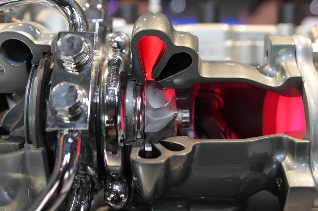
IIRC the Crecy had a lot of exhaust massflow but the exhaust was not particularly energeticwuzak wrote:A diagram showing the Rolls-Royce Crecy 2 stroke sleeve valve turbocompound engine.
Not sure how much power the turbine gave, but the Crecy had a lot of exhaust energy.
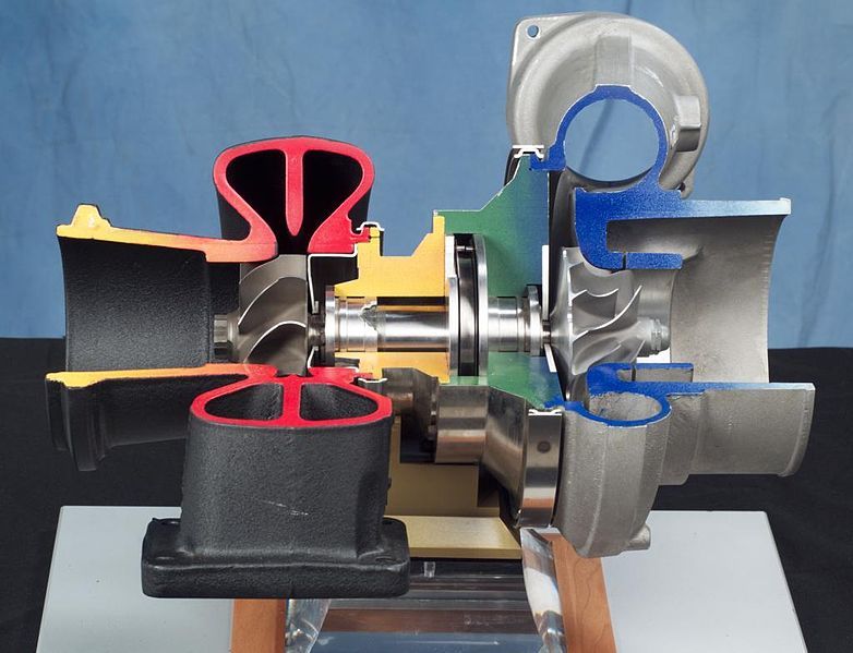
The Allison V-1710-127 (-E27) also had a single stage axial turbine. The base engine was 2000-2200hp, the turbocompound was 2900-3000hp. About 50% power improvement!
there being a large surplus of air going through the engine
the compounded Allison was made to use specially high grade Triptane-based fuel eg 200 PN
to give higher power via specially high mep, via 108" Hg induction pressure, (the CR being left as standard for this purpose)
ie your 50% (really 40%) improvement in max power was mostly due to the fuel, and mostly piston-to-crankshaft not compound
the same fuel allowed raised CR on the base engine, improving both power and efficiency
(this fuel was never used in service)
RETRO EDIT (for self)
the above paragraph is wrong re Triptane
wuzaks post at 1126 this day is correct re the genesis of the Allison compound
thanks for that, w
all these WW2 era aircraft engines had low CR ie 6:1-7:1 (sub-optimal in cruise) to allow temporary very high mep and power
(the Wright TC that was used in the real world gave 6% gain in cruise and 17% at takeoff power)
Wright stated that the TC benefit was to crankshaft power at low altitude and speed (the TC was for US Navy patrol aircraft)
ie that at high altitude and speed an engine would naturally convert exhaust energy into jet thrust without the TC
(so the base Allison and others would have more propulsion power in use than your testbench power would suggest)
they all had much more energetic exhaust than the 2014 F1, which will have one job to do, and about a 12:1 CR for that job
the TC recovery in these engines will be about 10%