Open Source Racecar

Post here information about your own engineering projects, including but not limited to building your own car or designing a virtual car through CAD.
User avatar
Tim.Wright
330
Joined: 13 Feb 2009, 06:29

Re: Open Source Racecar

Post

Greg Locock wrote:The way I do those is to work in front view and side view in excel. I draw a box where the hardpoints can go, then run massive Monte Carlo sims looking for the elusive best compromise between the various desired outcomes.
This is very interesting. So you do some basic 2D kinematic calcs in excel to give you things like variations of camber gain, rch, caster etc?

The idea to do something like this popped into my head last year while I was manually optimising some push rod geometry in adams. I realised it was largely a 2D problem that excel could solve in milliseconds... But in Adams the loop of changing the hardpoint, simulating and updating the curves in post processor was taking several mintues each iteration. By the end I'd already thrown my toys out of the cot and moved onto another problem without exploring the excel path.

Never heard of the Monte-carlo sim in excel before. A quick google search shows some pretty interesting stuff. This could be pretty helpful for work since I'm working on a new 5 link axle at the moment.

Greg Locock wrote:... for instance when we are looking at RCH vs bump steer vs camber gain, which is something we might tune quite late in a program ...
This caught my eye, do you always look at these three things together or did you just give three random characteristics as an example? I'm asking because they all seem relatively unrelated but it reads like you analyse them together.

Cheers

Tim
Not the engineer at Force India

Tommy Cookers
Tommy Cookers
642
Joined: 17 Feb 2012, 16:55

Re: Open Source Racecar

Post

Tim.Wright wrote:
Tommy Cookers wrote: 4130 was a US spec aimed at welded aircraft frames, for weight saving based on its high strength allowing use of thinner gauge
many countries have/had specs used for the same purpose, eg T45 in the UK
Germany must have its own specs ? (having originated this type of construction in 1916)

but this weight saving reduces crash resistance ?
this being related to elastic stability/buckling and deformation/fracture work post-buckling ?
I'm not following here. I don't know of any reduction in the crash resistance of 4130 steels. In fact, with its higher UTS I'd say it has more energy absorbtion potential so is much better in a crash. However, the effects that you mention post buckling are way beyond my knowledge. I'm really not a materials guy. Am interested to know where you got this information from though. Because like I said, if I choose a moly alloy steel, it will be for crash protection reasons mainly.
I'm not suggesting any deficiency with 4130 or similar materials
I am suggesting that the frames energy absorbtion in a crash is not strongly related to the UTS of the material used
the UTS is basically the load to failure regardless of energy
there are measures of energy to failure (regardless of load ?) ie impact tests
also % elongation to failure would allow determination of energy

4130 and other alloy steels have a high UTS but the % elongation to failure is not very high
mild steels have a quite low UTS etc but a very high % elongation to failure & have the best energy absorbtion of usual carbon steels
IMO the energy absorbtion (including elastic strain) of these two materials would be similar
impact test values should be available, my guess is that MS would win that one
mild steel is 0.16 - 0.3 % carbon (low carbon steel is 0.15% or less)
(low carbon steels EN1A show spectacular 19% elongation/energy absorbtion but their poor UTS would cost weight)

about 99% of (car) spaceframes were/are mild steel (and some of the others were Al alloy)
car spaceframes would be designed to a stiffness target, so high UTS is no benefit
(aircraft frames were/are designed to a strength target, so high UTS saves weight, and benefits pin-jointing)

the basic spaceframe can be very light even with MS (the Lotus 8 was 9.5 kg), but the feeding-in of external loads is not
light spaceframe cars 'in the day' were regarded as bad news in a crash
purists said that cleanly collapsed bays showed good design, and allowed the uncollapsed bays to be re-used
3 or 4 kg more from using slightly thicker tubing would be very beneficial in a crash (real-world cars have this ?)

nice car, anyway !
Last edited by Tommy Cookers on 24 Feb 2013, 11:32, edited 3 times in total.

User avatar
Tim.Wright
330
Joined: 13 Feb 2009, 06:29

Re: Open Source Racecar

Post

Fair enough, I haven't compared the tensile stress strain diagrams, but I figured if moly has a much higher uts and the same youngs modulus, then then energy would be higher. I don't really know how these materials perform after they yield, its something I will look into. I'd be happy to find a good justification to use low carbon steel though.
Not the engineer at Force India

Greg Locock
Greg Locock
235
Joined: 30 Jun 2012, 00:48

Re: Open Source Racecar

Post

Tim.Wright wrote: This is very interesting. So you do some basic 2D kinematic calcs in excel to give you things like variations of camber gain, rch, caster etc?
Never heard of the Monte-carlo sim in excel before. A quick google search shows some pretty interesting stuff. This could be pretty helpful for work since I'm working on a new 5 link axle at the moment.
....
This caught my eye, do you always look at these three things together or did you just give three random characteristics as an example? I'm asking because they all seem relatively unrelated but it reads like you analyse them together.
Yes, I use the old drawing board methods in Excel. Monte carlo is just a posh way of saying we stick random adjustments into each factor, and keep the best one! It is brute force, its great virtue is that unlike more economical approaches, say GA, it doesn't get stuck in local optima, and unlike a taguchi DOE a run that fails is not important. Frankly these days CPU time is free, so if it takes all nigh to tun 100 000 runs, no big deal.

RCH, bump steer and camber gain are all affected by changes in FV geometry, so I do work on them togather. Bump steer is finalised last by raising or lowering the rack or outer tie rod, but I need to make the design guys aware that they can't just play with RCH without worrying about it.

Incidentally i'd be very leary of regarding mechanical trail as a way of getting low efforts.

At zero g you are probably running 30 mm or so of pneu trail. At say 50% max you are running 15mm, and at max lat you have 0mm

So your curve of Mz is an inverted parabola. If you have 0 MT then that is also your curve of effort. This would make it very easy to sense the approach to max lat, but is disconcerting as the steering wheel will run away as you approach it. (Ergonomically a negative slope of SWT/SWA is a bad thing control wise)

OTOH if you have 30 mm of MT, then your effort curve would be virtually flat between 50% and 100% lat. That doesn't sound very clever either! (obviously you need to look at 75% to see if that is higher than the other two)

So I'd have a play with a typical tire model. It's worth noting that big boys don't get it right - the original X5 had a negative effort slope when cornering at 0.6g , which made it rather disconcerting if you made a correction once in a corner.

It's quite a subtle thing, i think, lots of MT gives you a nice linear curve of SWT/latacc, but little warning of impending doom, while zero MT gives you a crazy curve of SWT and latacc, but lots of information at the peak.

Interesting stuff.

MileticDesign
MileticDesign
0
Joined: 01 Sep 2013, 08:41

Re: Open Source Racecar

Post

Image
screen capture program

here is some sketch I made for body work, what you think?

my portfolio: http://www.miletic-design.portfoliobox.me/project-rrt

User avatar
Tim.Wright
330
Joined: 13 Feb 2009, 06:29

Re: Open Source Racecar

Post

MileticDesign wrote:http://postimg.org/image/cknj1s1c5/full/
screen capture program

here is some sketch I made for body work, what you think?

my portfolio: http://www.miletic-design.portfoliobox.me/project-rrt
Sweet man, thats cool (apart from those tyres ;) ). Stylingwise I was hoping to create something simple like that. No loud spoilers or other BS.

Was this drawn based on any of the dimensions I have posted? Or is it just a concept? If you want Im happy to shoot off a STP file of the chassis and wheels since I want to keep the "open source" thing going i.e. I'm trying not to use anything of a confidential nature in this design so if anybody wants info/data I'm happy to send it out.

This project has been quiet in the last few months. I've done a tiny bit more work on the design (actually by hand on my drawing board) but haven't got around to posting it yet. I made an ergo rig to position the sea back angles and steering wheel pos and I'm reasonably happy with what I have got there now. I will upload some pictures of that at some point. Unfortunately I made it from untreated pine and my flat reference base has twisted because I accidentally spilt beer on it on 2 seperate occasions... Knob...

I have an idea for a mechanically interconnected suspension which I'd one day like to build. The dream would be to put it into this car. When I have a little more time, I will post the details of it up here. I don't have the time, energy or desire to patent it or commercialise it so I don't have a problem with putting it in a public forum. Who knows, maybe its been done before (actually I'm sure its been done in hydraulic or an active form before). I will try to upload something in the next couple of weeks about it.

T
Not the engineer at Force India

MileticDesign
MileticDesign
0
Joined: 01 Sep 2013, 08:41

Re: Open Source Racecar

Post

Tim.Wright wrote:
MileticDesign wrote:http://postimg.org/image/cknj1s1c5/full/
screen capture program

here is some sketch I made for body work, what you think?

my portfolio: http://www.miletic-design.portfoliobox.me/project-rrt
Sweet man, thats cool (apart from those tyres ;) ). Stylingwise I was hoping to create something simple like that. No loud spoilers or other BS.

Was this drawn based on any of the dimensions I have posted? Or is it just a concept? If you want Im happy to shoot off a STP file of the chassis and wheels since I want to keep the "open source" thing going i.e. I'm trying not to use anything of a confidential nature in this design so if anybody wants info/data I'm happy to send it out.

This project has been quiet in the last few months. I've done a tiny bit more work on the design (actually by hand on my drawing board) but haven't got around to posting it yet. I made an ergo rig to position the sea back angles and steering wheel pos and I'm reasonably happy with what I have got there now. I will upload some pictures of that at some point. Unfortunately I made it from untreated pine and my flat reference base has twisted because I accidentally spilt beer on it on 2 seperate occasions... Knob...

I have an idea for a mechanically interconnected suspension which I'd one day like to build. The dream would be to put it into this car. When I have a little more time, I will post the details of it up here. I don't have the time, energy or desire to patent it or commercialise it so I don't have a problem with putting it in a public forum. Who knows, maybe its been done before (actually I'm sure its been done in hydraulic or an active form before). I will try to upload something in the next couple of weeks about it.

T
Hi, I am so glade you like it and I see you try to do LMP style body so I take some of that in my design.
This is just a concept and I would love to see STEP file so we can make some changes on design, did you have dropbox so we can share the files?

Smokes
Smokes
4
Joined: 30 Mar 2010, 17:47

Re: Open Source Racecar

Post

Quick question.

What do I need to search for, in order to learn how to 2d suspension design in excel.
I have a COPY of RCVD on a shelf somewhere.

from looking a the supsionsion from the front of the vechilce and suspion is a unequal length wish bone setup.

Y AXIS IS UP DOWN
x AXIS IS LEFT RIGHT
z AXIS IS FRONT TO BACK

I ASSume its a XY trace plot with fixed points to represent the hard points, You Simulate the camber gain in bump by using trig on the control arm and using the hypoteneuse of the triangle as the control arm length will give value X and bump would be value Y. And the same for the camber link?

How do you plot the path of the unfixed points as the suspension goes from nomal ride height to hitting the bump rubbers and maximum allowable droop. Do you just add another set of columns based on the trig values of Y, X eqauls a particular value.
How do you simulate bump steer in 3d I assume 2d lookng from the top of the vechicle you can work out X beign the opposite of the Hypoteneuse(fixed length of the steering arm when the wheels are straight).

What happens to the equations when the arm is horizontal?

I have used excel extensivly in engineering but never found the time or opportunity to set up linkage charts.

User avatar
Tim.Wright
330
Joined: 13 Feb 2009, 06:29

Re: Open Source Racecar

Post

I have a 2d excel sheet I made for this project I can share. When I have some time later today I will roughly explain how I did it. Basically you break the problem up into lots of triangles but there are a few gotchas you eed to be wary of.

For 3d, its possible analytically but I use Adams because life is too short. I have a matlab script that calculates link forces in 3d but when I started looking at thw kinematics its quite a massive job and thought my time was better spent elsewhere.
Not the engineer at Force India

User avatar
Tim.Wright
330
Joined: 13 Feb 2009, 06:29

Re: Open Source Racecar

Post

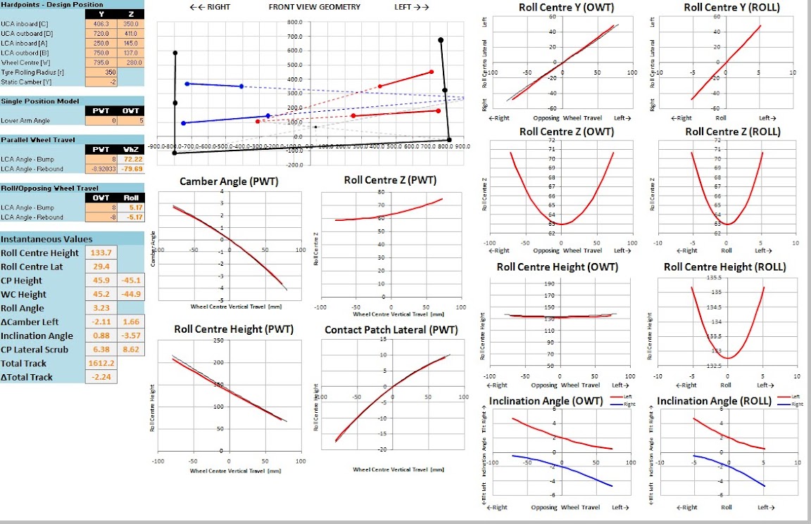
Smokes, I've uploaded my 2D front view kinematics excel sheet I made a few weeks ago.
https://docs.google.com/file/d/0B9R57wq ... sp=sharing

I hope it works. Let me know if there are problems. I validated it against adams with a simple double wishbone geometry and rigid tyres. The results were pretty damn good. Here is the file with the adams comparison (Adams are the black curves, excel calculations are red curves)

Image

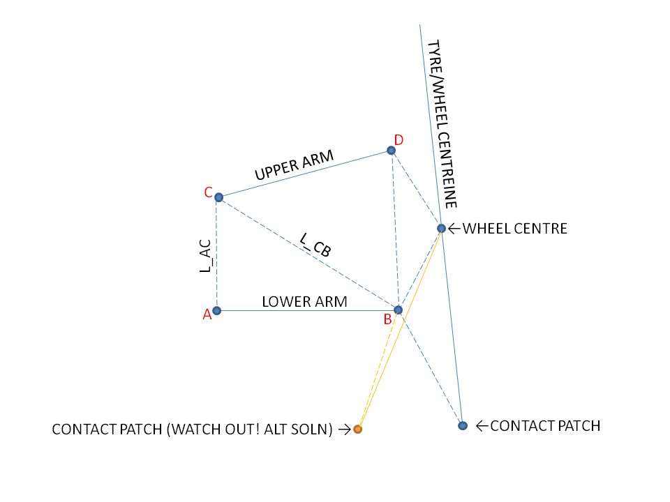
Like I said before, I broke the problem into triangles and used trig to work my way through until I knew all the links and all the angles. This is basically how I broke the problem down:

Image

I started by giving an input angle of the lower arm with respect to the horizontal. This defined ptB.
With ptB known and ptC known (since its one of the suspension hardpoints) you can calculate L_CB
With the length of the lower arm, L_CB and L_AC known you can calculate all the internal angles of that triangle
You can calculate the kingpin length as the distance between ptB and ptD in the static position.
With the kingpin length, the upper arm length and L_CB known you can calculate all the internal angles of that triangle
Then you can use the angles and lengths to calculate the moving positions of ptB and ptD

...and basically you proceed like that. Starting with the input angle of the lower arm and then calculating all of the triangles to locate pt B, ptD, wheel centre and the contact patch. Watch out for some triangles which have two possible solutions (e.g. like I've shown in orange).Excel will only give you one solution so you need to make sure its giving the right one. I found this out the hard way when I saw my camber and contact patch locations were not calculating right. What was happening was excel was solving for the wrong case. I solved this by seting up a hub coordinate system (located on the kingpin axis B-D) and defined the contact patch and wheel centre in that coordinate system. By eliminating the triangle trig from those two points, I removed the abiguous case.

There are of course other ways to do this. Such as 4 bar link theory. I got annoyed at that because I couldn't get it working in 5 mins so I went down the triangles route... The 4 bar link approach would be more robust (because I don't think it has problems with ambiguous cases of the triangle solutions) but yea, thats just not how I roll.

By the way, there is nothing in Milliken which will tell you how to do this calculation. I actually don't know of any books with this explained, but if you read up on 4 bar link theory I think you will find a good solution.

Then once you have your version working well, its only a few changes required to make it into a side view kinematics calculator to find anti dive/lift/squat/raise etc...

Enjoy.

T

PS: Miletic, I will get your step file tomorrow night, I forgot to convert it today.
Not the engineer at Force India

Greg Locock
Greg Locock
235
Joined: 30 Jun 2012, 00:48

Re: Open Source Racecar

Post

thanks Tim, when I get back to my proper computer I'll check that against wishbone.bas.

User avatar
Tim.Wright
330
Joined: 13 Feb 2009, 06:29

Re: Open Source Racecar

Post

Cheers Greg, that will be interesting.

One thing you could probably answer. The curves for roll centre height and lateral position only match up to Adams when I do a simulation with ISO (dependent) coordinates. When I do a normal opposing wheel travel (with independent coordinates) I get a completely different result for the roll centre. And as usual the difference isn't explained properly in the Adams documentation. What is your take on this?

At the end of the day, I'm not the kind of person to get too excited about roll centre movements (especially when one calculation in adams says its at Y=10mm and the other says its at Y=-500mm) but I'd like to understand the Adams convention.

T
Not the engineer at Force India

Smokes
Smokes
4
Joined: 30 Mar 2010, 17:47

Re: Open Source Racecar

Post

If i have a supension setup, where the kingpin of the steering is offset away from the lower and upper pivot points.
Would the excel sheet posted (I can't download it) be able to still give a good bias to how the linkage behaves?

Thanks

MileticDesign
MileticDesign
0
Joined: 01 Sep 2013, 08:41

Re: Open Source Racecar

Post

Tim.Wright wrote:Smokes, I've uploaded my 2D front view kinematics excel sheet I made a few weeks ago.
https://docs.google.com/file/d/0B9R57wq ... sp=sharing

I hope it works. Let me know if there are problems. I validated it against adams with a simple double wishbone geometry and rigid tyres. The results were pretty damn good. Here is the file with the adams comparison (Adams are the black curves, excel calculations are red curves)

https://lh6.googleusercontent.com/-4yrR ... _valid.jpg

Like I said before, I broke the problem into triangles and used trig to work my way through until I knew all the links and all the angles. This is basically how I broke the problem down:

https://lh4.googleusercontent.com/-ANSr ... iagram.jpg

I started by giving an input angle of the lower arm with respect to the horizontal. This defined ptB.
With ptB known and ptC known (since its one of the suspension hardpoints) you can calculate L_CB
With the length of the lower arm, L_CB and L_AC known you can calculate all the internal angles of that triangle
You can calculate the kingpin length as the distance between ptB and ptD in the static position.
With the kingpin length, the upper arm length and L_CB known you can calculate all the internal angles of that triangle
Then you can use the angles and lengths to calculate the moving positions of ptB and ptD

...and basically you proceed like that. Starting with the input angle of the lower arm and then calculating all of the triangles to locate pt B, ptD, wheel centre and the contact patch. Watch out for some triangles which have two possible solutions (e.g. like I've shown in orange).Excel will only give you one solution so you need to make sure its giving the right one. I found this out the hard way when I saw my camber and contact patch locations were not calculating right. What was happening was excel was solving for the wrong case. I solved this by seting up a hub coordinate system (located on the kingpin axis B-D) and defined the contact patch and wheel centre in that coordinate system. By eliminating the triangle trig from those two points, I removed the abiguous case.

There are of course other ways to do this. Such as 4 bar link theory. I got annoyed at that because I couldn't get it working in 5 mins so I went down the triangles route... The 4 bar link approach would be more robust (because I don't think it has problems with ambiguous cases of the triangle solutions) but yea, thats just not how I roll.

By the way, there is nothing in Milliken which will tell you how to do this calculation. I actually don't know of any books with this explained, but if you read up on 4 bar link theory I think you will find a good solution.

Then once you have your version working well, its only a few changes required to make it into a side view kinematics calculator to find anti dive/lift/squat/raise etc...

Enjoy.

T

PS: Miletic, I will get your step file tomorrow night, I forgot to convert it today.
ok Tim no prob. I will make some more sketches

User avatar
Tim.Wright
330
Joined: 13 Feb 2009, 06:29

Re: Open Source Racecar

Post

Hey guys,

I have uploaded my cad assy if anyone are interested:
https://skydrive.live.com/redir?resid=5 ... 5-FdeFKqSE

Tim
Not the engineer at Force India