F1 Cylinder Head Design and Pneumatics, a closer look

All that has to do with the power train, gearbox, clutch, fuels and lubricants, etc. Generally the mechanical side of Formula One.
Brian.G
Brian.G
334
Joined: 10 Dec 2010, 23:52
Location: Ireland

Re: F1 Cylinder Head Design and Pneumatics, a closer look

Post

PVDL wrote:Brian, WOW! Thanks for this thread. I got more out of this than reading a years worth of RET magazine!!

Couple of questions...

Regarding the water cores, which sand technique is used to make them?

Are they baked before or after joining the segments to each other and what type of glue/cement is used in the process?


Also the nut seats for the head studs are quite a trick to machine. I can guess how they did it, but I wonder what level of precision they accomplished. Maybe it doesn't matter if they used spherical washers under the nuts?

Anyway, fascinating stuff and many thanks to you!!


Cheers, Paul
Paul,

If this is the case you will love the next thread - but more on that in a week or two.

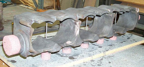
Regards the cores, I cannot guess which cores they used, but they were air set or sodium silicate bonded co2 cured.

As for the glue, I use an Isopropyl alcohol based adhesive since nearly all my core work is with sodium silicate bonded sand - since water is used to wash out these cores(it breaks down the bond)you cannot really used a waterbase glue for bonding as the bond is less robust - BUT - water based glue is sometimes used having said that as it is more environmentally friendly. There are a load of glues out there though, the main thing with all of them is to make sure they are dry before pouring as any steam or gas created if alloy hits semi dry glue will make either a gas pocket, or a blow hole.

All cores are set/dried before bonding/building.

The nut seats are pretty straightforward to machine, I dont know what way you have guessed but Im certain these were done with a back counterbore cutting tool. Other names rear spot face tool, back spotfacer, rear counterborer.

The method is drill all head bolt holes from the block side. These get reamed to a high surface finish. A long slender tool the same diameter of drilled hole is then passed all the way through until the tip exits under the cam trays. The tool can either have a flap that is then hinged out against a pin in bar pocket with contains a carbide insert and the spot facing can commence. The machine is powered down, the flap c/w insert hinged into boring shaft pocket and the entire bar withdrawn again ready for insertion into next hole. That is one method, another is grubbing a mini cutter block onto the end of the shaft once it is passed through.
A while back I designed a new type of tool for doing same without all the fiddling whereby the long slender bar was inserted into head bolt hole exited under cam area. The 12mm bar was drilled in the center and the cutter end was turned down to form a small shoulder. The end section was 10mm in diameter and 20mm long. The bar was counterbored on the exit end 6mm in diameter to a depth of 15mm. On the inside of this counterbore a groove was cut similar to one for an internal circlip but wider(2mm wide). This groove went to a depth of 1.75mm leaving a wall thickness of just .25mm in that area. The end of the counterbore was blocked off with a tig welded plug. The bar was inserted into headbolt hole to the required exit depth. The mini cutterblock was placed on the end of the bar and the hydraulic pressure turned on. This fed oil into the bar - down its length and into the end at cutter block. The oil pressure slightly swelled the thin area at groove locking the block on. It proved to be very fast and less fiddly that the hinged flap method. Oil was introduced into the bar though a radial drilling via a sealed live manifold near collet similar to how coolant is fed into deep drills.
Sadly I cant share any pictures of the above as someone else was paying at the time.

There are many ways of doing back counters but it all depends on how many you have to do, whos paying, and what machines you have to work with. Some can even actuate the hinged flap with a pull/push rod similar to the pull stud drawbar affair.
Heres an example of an auto spotter,

http://www.heuletool.com/pages/catalog/images/18.pdf

Photobucket is acting up the last day or two but as soon as its back Ill post the rest of the basic port dimensions,

Brian,
If you think you cant, you wont, If you think you can, you will

schmidtmotorworks
schmidtmotorworks
0
Joined: 06 Sep 2013, 22:01

Re: F1 Cylinder Head Design and Pneumatics, a closer look

Post

Thank you for taking the time to take the pictures and post them! (fellow pattern maker here)
By the looks of some of the water passages, particularly between the valves, I got the impression that the core boxes may have been shaped by hand rather than CNC milled. Looking at them in person do you have any impression about how the tooling was made? Any signs that wood is used? Any sign that the final product was not related to a 3D CAD model?
I almost always cut everything direct in solid urethane blocks but have been impressed by people that are really skilled at working with a positive master, plaster and then pouring.

tok-tokkie
tok-tokkie
37
Joined: 08 Jun 2009, 16:21
Location: Cape Town

Re: F1 Cylinder Head Design and Pneumatics, a closer look

Post

There are a load of glues out there though, the main thing with all of them is to make sure they are dry before pouring as any steam or gas created if alloy hits semi dry glue will make either a gas pocket, or a blow hole.
In the video you linked of the heads being cast I wondered what the flames are that dance in the vents. What is burning?

riff_raff
riff_raff
132
Joined: 24 Dec 2004, 10:18

Re: F1 Cylinder Head Design and Pneumatics, a closer look

Post

Brian.G wrote:Regarding the water cores, which sand technique is used to make them? Are they baked before or after joining the segments to each other and what type of glue/cement is used in the process? Cheers, Paul
The questions about sand cores and binders is quite interesting. I have designed a few aircraft gearbox main housing sand castings that incorporated lots of small diameter (.25") lube oil pipes and thin walls (.16"). I recall one visit to the foundry where I saw how the small diameter sand cores were made. The final step in the process involved hand drilling tiny vent holes down the middle of the cores, the purpose of which was to prevent outgassing from the core binder from
creating gas holes in the thin pipe walls.
"Q: How do you make a small fortune in racing?
A: Start with a large one!"

Brian.G
Brian.G
334
Joined: 10 Dec 2010, 23:52
Location: Ireland

Re: F1 Cylinder Head Design and Pneumatics, a closer look

Post

riff_raff wrote:
Brian.G wrote:Regarding the water cores, which sand technique is used to make them? Are they baked before or after joining the segments to each other and what type of glue/cement is used in the process? Cheers, Paul
The questions about sand cores and binders is quite interesting. I have designed a few aircraft gearbox main housing sand castings that incorporated lots of small diameter (.25") lube oil pipes and thin walls (.16"). I recall one visit to the foundry where I saw how the small diameter sand cores were made. The final step in the process involved hand drilling tiny vent holes down the middle of the cores, the purpose of which was to prevent outgassing from the core binder from
creating gas holes in the thin pipe walls.
Indeed, you have to let the cores breath or you will risk an internal core blow out. Drilling or vee scraping is common practice post cure to provide venting. For large holes, or added risers a 15mm twist drill, or even 35mm flat bit will race through the cured sand without making a mess. If a zircon/graphite wash is applied to cores the core plug areas have to be left as is, or the coating scraped off - otherwise the core will fail to breath and explode in situ.
On many thin cores as you describe, a small central vent is sometimes formed with a length of 1mm wire at time of packing the core box. This is then removed(slid out) and this vent aids the spreading of co2 gas through the core for binder solidification. Once the core has been given the wash, this same hole can then act as the path for the gasses as you describe.
One of the most annoying things that can happen post pour is a poorly fitting core print - the metal flows around the print and out to the end of core, blocking the vent hole. A dudd part will arise if this happens with blow out a sure thing. Glue or a better fitting core print fixes this.

Below you can see what I mean, the core print locations are left un coated and free to breath into the main mould,

Image

Credit to DMD Australia Austin Healey for the Image above - its not mine.

As mentioned before, lot of ways of going about mould making and they are all different. But indeed drilling or scraping is common practice afterwards if making those impressions pre cure is awkward, or impossible when in the core box.
Scraping can also be done in the r+d filling phase, whereby a larger gate can be scraped out, or extra risers added. These adjustments can be then added to the patterns for for future moulding, no drilling or scraping is necessary from any moulds pulled from the boxes then thereafter.

Brian,

Will try answer other questions tomorrow as best I can,
If you think you cant, you wont, If you think you can, you will

zenji
zenji
0
Joined: 23 Sep 2013, 01:22
Location: Australia

Re: F1 Cylinder Head Design and Pneumatics, a closer look

Post

Firstly, wow. Must have been a big gulp taking that first cut on the bandsaw.
Could anybody correct my facts please?
This looks like the Hart V10 engine, raced by TRW during their Repsol sponsorship period???
This motor was based on the DFR cosworth V8??? And undertook its own evolution through TRW???
It was also used for a few seasons in Hillclimbing coupled to a Jordan gearbox???
Love those ports, the shim bucket / tapered lobe cam system looks a bit dated though.

theo
theo
0
Joined: 23 Sep 2013, 11:39

Re: F1 Cylinder Head Design and Pneumatics, a closer look

Post

I am absolutely sure it is the Hart V10 engine.
The subsequent TWR600 engines used finger followers that provided a slight 'wiping' action on the radial valves, rather than tapered cam lobes and buckets as the HART engine did.
Great images though, thanks very much for information, very interesting.

theo
theo
0
Joined: 23 Sep 2013, 11:39

Re: F1 Cylinder Head Design and Pneumatics, a closer look

Post

Hello Brian,
Out of curiosity would it be possible for you to take a few pictures of the blue water jacket core with the ruler next to them. Im interested in the height of the jacket as well as the angles of the two 'slopes' where the jacket goes around the inlet and the exhaust ports.
Thanks in advance

Brian.G
Brian.G
334
Joined: 10 Dec 2010, 23:52
Location: Ireland

Re: F1 Cylinder Head Design and Pneumatics, a closer look

Post

Guys, sorry all for delay on this, the main problem is image hosting atm. As it turned out, the issuse was with my pc, and not photobucket after countless support mails. I have to re configure a few drivers and we should be good to go then. Recently did a pc cleanup and it screwed with a few things.

Brian,
If you think you cant, you wont, If you think you can, you will

riff_raff
riff_raff
132
Joined: 24 Dec 2004, 10:18

Re: F1 Cylinder Head Design and Pneumatics, a closer look

Post

Some of the lightweight aircraft gearbox housing sand castings I described in my previous post were worth over $25K as delivered. So every effort was made by the foundry to prevent scrapping a casting. The foundry probably had around $5K invested just getting a single mold thru QA and ready for filling. Then there were the costs for dye penetrant, radiographic and borescope inspection, weld repair of porosity flaws and plugging of core supports, heat treatment, pressure testing, machining of tooling points using a targeting fixture, dimensional inspection, and finally cleaning and chem film coating.

Most of these sand castings were made using bottom filling from a crucible pressurized by inert gas.
"Q: How do you make a small fortune in racing?
A: Start with a large one!"

Desertrunner
Desertrunner
0
Joined: 25 Oct 2013, 00:20

Re: F1 Cylinder Head Design and Pneumatics, a closer look

Post

Great info, most appricated

obradorista
obradorista
0
Joined: 20 Sep 2012, 09:39

Re: F1 Cylinder Head Design and Pneumatics, a closer look

Post

This is incredible. Great great thread.

Robby
Robby
0
Joined: 25 Sep 2013, 21:36

Re: F1 Cylinder Head Design and Pneumatics, a closer look

Post

theo wrote:I am absolutely sure it is the Hart V10 engine.
Perhaps dating back to ca. 2001?

lbrown
lbrown
0
Joined: 20 Dec 2013, 05:10

Re: F1 Cylinder Head Design and Pneumatics, a closer look

Post

thanks for this ...i would love to see more especially the more detail on the pnuematic valve actuation and the barrel throttle valve....thanks again for this great post.

lbrown
lbrown
0
Joined: 20 Dec 2013, 05:10

Re: F1 Cylinder Head Design and Pneumatics, a closer look

Post

i am very thankful that you posted this...it is the best tech i have seen in a long time....i would though greatly appreciate more details on the pnuematic valve setup...what pressure where they run at?...exactly what kind of seal was used on the pnuematic piston ....