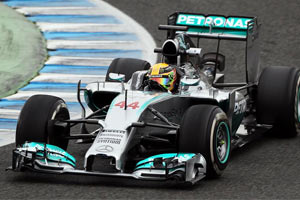
Mercedes AMG F1 W05

A place to discuss the characteristics of the cars in Formula One, both current as well as historical. Laptimes, driver worshipping and team chatter do not belong here.
User avatar
dans79
267
Joined: 03 Mar 2013, 19:33
Location: USA

Re: Mercedes AMG F1 W05

Post

Pup wrote:
turbof1 wrote: So if Merc are within the regs here, why did Lotus have to do the asymmetrical thing? Would Merc not also have to lop 50mm off one side?
it has to be a continuous cross section 50mm (I think) back from the tip. Since the lotus 'tusks' aren't connected one has to be longer than the other so that when a cross section is calculated they only get one area and not two. Since the Merc 'tusks' are connected, you will get one continuous area that looks like an upside down U.
201 105 104 9 9 7

User avatar
turbof1
Moderator
Joined: 19 Jul 2012, 21:36
Location: MountDoom CFD Matrix

Re: Mercedes AMG F1 W05

Post

Pup wrote:
turbof1 wrote:
dren wrote:I would argue Merc is following not bending the rules. The same goes for Lotus and everyone else. I'm glad that they came to this solution; it looks by far the best.
That's more depending on the perspective you are looking from :P. Which is true in its own right of course; the truth is always multi-dimensional. And from your perspective you are right: FIA allows it, so they should use it. Again, I love these kind of things. A month ago I worked out this concept on my own, without the faintest hint of teams actually using it.
So if Merc are within the regs here, why did Lotus have to do the asymmetrical thing? Would Merc not also have to lop 50mm off one side?
Mercedes made smart use of the vanity panel. We might see Lotus doing this as well.

@Dans: I don't think it would be viewed as one single cross section if both pylons were equally long. I think they made one pylon shorter then the other, but then used the vanity panel to cover it up.
#AeroFrodo

User avatar
thomin
3
Joined: 23 Feb 2012, 15:57

Re: Mercedes AMG F1 W05

Post

dans79 wrote:
thomin wrote:
dans79 wrote:just to prove I'm not seeing things, I have made the seam red in the two photos. You can see that in the one the nose has the teal stripes and it doesn't in the other.

http://s29.postimg.org/6cypt581z/offical.jpg

http://s23.postimg.org/fo737nykr/today.jpg
Sure, so the nose wasn't painted properly. I'm sure they have several of them, what is your point?
The point is, that they had a wing/nose/pillar whatever you want to call it failure today, and the car that ran today is aesthetically different from official photos. Thus 3 things spring to mind.

1. the official photos didn't use a real nose. so is merc just barely getting done and rushing and hence no paint.
2. the wing that was run today was a new concept, and it broke.
3. someone forgot to paint the wing, or put the right one on this morning. (no likely considering how anal the teams are about stuff like this)
Actually, it may very well be a combination of all those points. It's natural for new parts that were rushed to not have all the details and similarly, it can also happen that real life stresses are different than they were simulated which leads to failures. Hence testing.

scottracing
scottracing
0
Joined: 06 Dec 2011, 01:39
Location: Cologne

Re: Mercedes AMG F1 W05

Post

Not surprised about the wing failure with the amount of load that joint will have. There is no mechanical fastening like previous noses and from the dramatic failure it could be a bond line glue failure or delamination of the carbon laminate due tothe stresson the small attachment area. Would love to see some close up photos of the front end post crash.

User avatar
thomin
3
Joined: 23 Feb 2012, 15:57

Re: Mercedes AMG F1 W05

Post

scottracing wrote:Not surprised about the wing failure with the amount of load that joint will have. There is no mechanical fastening like previous noses and from the dramatic failure it could be a bond line glue failure or delamination of the carbon laminate due tothe stresson the small attachment area. Would love to see some close up photos of the front end post crash.
There was an image of the broken wing on the backseat of some trackside car in my twitter timeline...I'll try to dig it up again. But to my layman's eyes it looked like the carbon joints failed.

User avatar
dans79
267
Joined: 03 Mar 2013, 19:33
Location: USA

Re: Mercedes AMG F1 W05

Post

turbof1 wrote: @Dans: I don't think it would be viewed as one single cross section if both pylons were equally long. I think they made one pylon shorter then the other, but then used the vanity panel to cover it up.

it's possible, but i think that would be an inferior design, because of the asymmetry.

Quoting scarabs:
Firstly the nose must meet a minimum tip height, this means the area 50mm behind the actual tip must be centred at 185mm above the cars reference plane (the bottom of the stepped floor), additionally this cross section must not be lower than 135mm (10mm above the front wing) or above 300mm. The cross section for the tip must be 9000mm2
http://scarbsf1.com/blog1/2014/01/23/f1 ... ger-noses/


as I read this.
1. go back from the tip of the nose 50 mm and slice down through it to make a sectional surface.
2. make sure the top of the surface is bellow 300mm
3. make sure the bottom of the surface is above 135mm
4. make sure the cross sectional area is at least 9000mm2 (I assume 9000 is a minimum and not an exact value)
5. make sure the center of the area is centered at 185mm above the reference plane.

The way I read this you could still have 300mm high noses if you used an inverted U shaped nose. The sectional area would be centered on the car center-line. All you would need to do is get the shape right to get the vertical center on target.


does anyone have the actual rule, not a quote of them?
201 105 104 9 9 7

User avatar
thomin
3
Joined: 23 Feb 2012, 15:57

Re: Mercedes AMG F1 W05

Post

thomin wrote:
scottracing wrote:Not surprised about the wing failure with the amount of load that joint will have. There is no mechanical fastening like previous noses and from the dramatic failure it could be a bond line glue failure or delamination of the carbon laminate due tothe stresson the small attachment area. Would love to see some close up photos of the front end post crash.
There was an image of the broken wing on the backseat of some trackside car in my twitter timeline...I'll try to dig it up again. But to my layman's eyes it looked like the carbon joints failed.
LOL, I was looking through my twitter-timeline, finding nothing...then I realized that I saw the picture in this very thread:
http://www.f1technical.net/forum/viewto ... 63#p479963

Image

User avatar
turbof1
Moderator
Joined: 19 Jul 2012, 21:36
Location: MountDoom CFD Matrix

Re: Mercedes AMG F1 W05

Post

dans79 wrote:
turbof1 wrote: @Dans: I don't think it would be viewed as one single cross section if both pylons were equally long. I think they made one pylon shorter then the other, but then used the vanity panel to cover it up.

it's possible, but i think that would be an inferior design, because of the asymmetry.
No because the vanity panel is there just because of that: the make it completely symmetric again. Nothing inferior about that.

I believe the U shape you are referring to only applies to the chassis.

The rules you mentioned just defined the legality box. The single cross section rules are these:
3.7.8 Only a single section, which must be open, may be contained within any longitudinal vertical
cross section taken parallel to the car centre line forward of a point 150mm ahead of the front
wheel centre line, less tha
n 250mm from the car centre line and more than 125mm above the
reference plane.
Any cameras or camera housings approved by the FIA in addition to a single inlet aperture for
the purpose of driver cooling (such aperture having a maximum projected surface a
rea of
1500mm
2
and being situated forward of the section referred to in Article 15.4.3) will be
exempt from the above.
3.7.9 No bodywork situated forward of the line A-A referred to Drawing 5 may extend above a diagonal line from a point on A-A and 625mm above the reference plane to a point 50mm rearward of the forward-most point of the impact absorbing structure defined in Article 15.4.3 and 300mm above the reference plane. No bodywork situated forward of the forward-most point of this diagonal line may be more than 300mm above the reference plane.
With the exception of a transparent windscreen, antenna or pitot tubes, no bodywork situated between the line A-A referred to in Drawing 5 and the secondary roll structure may lie more than 625mm above the reference plane.
2014 F1 Technical Regulations 12/88 9 December 2013
© 2013 Fédération Internationale de l’Automobile
Any bodywork situated above the impact absorbing structure defined by Article 15.4.3 or above the survival cell, and forward of the line B-B, must be of prescribed laminate, details of this laminate may be found in the Appendix to the Technical Regulations.
Last edited by turbof1 on 29 Jan 2014, 00:04, edited 2 times in total.
#AeroFrodo

PhatalOne
PhatalOne
0
Joined: 01 Jul 2013, 18:31

Re: Mercedes AMG F1 W05

Post

scottracing wrote:Not surprised about the wing failure with the amount of load that joint will have. There is no mechanical fastening like previous noses and from the dramatic failure it could be a bond line glue failure or delamination of the carbon laminate due tothe stresson the small attachment area. Would love to see some close up photos of the front end post crash.
I will preface that I did not get to see any of testing today. Could it have been a failure due to the wing making contact with the pavement?

In my lay opinion, they seem to want the wing to flex toward the ground under load as Red Bull has done in the past. I wonder if they didn't have the suspension dialed in quite right to account for the weight transfer under braking combined with the deflection of the wing under load.

Blanchimont
Blanchimont
214
Joined: 09 Nov 2012, 23:47

Re: Mercedes AMG F1 W05

Post

I think the Mercedes trick is the following: They define an inverted U section with the sides making up for almost all of the cross section of 9000mm². If i set the center of the area of the cross section to 185mm, this means that the cross section, to achieve the maximum possible height, extends from 135mm to 235mm above the reference plane. The sides would then be 9000/2/100 = 45mm wide. But we need to connect these two sides, that's the top of the inverted U. This could be very tiny, for example 0,1mm high bar which influences the 9000mm² and the center of area only marginally. We could even connect the two sides by a (mathematical) line which has a cross section of 0mm² and therefore doesn't influence the center of area at all. :mrgreen:

Behind the cross section 50mm behind the tip, the connection of the sides could increase in height and form the crash structure.

Image
Dear FIA, if you read this, please pm me for a redesign of the Technical Regulations to avoid finger nose shapes for 2016! :-)

User avatar
dans79
267
Joined: 03 Mar 2013, 19:33
Location: USA

Re: Mercedes AMG F1 W05

Post

Ok I think I found the appropriate rules.

http://www.fia.com/sites/default/files/ ... -12-09.pdf
15.4.3
15.4.3 
An impact absorbing structure must be fitted in front of the survival cell. This structure need 
not be an integral part of the survival cell but must be solidly attached to it. No part of this 
structure may lie more than 525mm above the reference plane. It must have a single external 
cross section, in horizontal projection, of more than 9000mm² at a point 50mm behind its 
forward-most point. Furthermore : 
   a) No part of this cross-section may lie more than 250mm or less than 135mm above the 
       reference plane. 
   b) The centre of area of this section must be no more than 185mm above above the reference 
        plane and no less than 750mm forward of the front wheel centre line.

thus IMO:
1) two equal length "tusks" are illegal.
2) Lotus style uneven tusks are legal.
3) unequal tusks with a vanity cover should be legal unless the fia rules the vanity panel was for the step only.
4) an upside down U is legal because it has one continuous area.

I think the key to the U being legal is that rule doesn't say anything about surface concavity. If the rule said no concavity then both Merc and Ferrari would be in trouble. If Merc gets in trouble for anything it will be the camera mounts.
Last edited by dans79 on 29 Jan 2014, 01:15, edited 1 time in total.
201 105 104 9 9 7

User avatar
dans79
267
Joined: 03 Mar 2013, 19:33
Location: USA

Re: Mercedes AMG F1 W05

Post

Blanchimont has it.

If you taper the sides at the top you can make them even taller and still keep the area center at 185mm.
201 105 104 9 9 7

User avatar
SectorOne
166
Joined: 26 May 2013, 09:51

Re: Mercedes AMG F1 W05

Post

Timstr wrote:Oddly, I have not seen any comments from the usual tech pundits on the lower front wishbone arrangement.
I don't think I've ever seen the legs spaced so closely together.

http://img2.auto-motor-und-sport.de/Lew ... 751082.jpg
Some more images, looks interesting.

Image
"If the only thing keeping a person decent is the expectation of divine reward, then brother that person is a piece of sh*t"

beelsebob
beelsebob
85
Joined: 23 Mar 2011, 15:49
Location: Cupertino, California

Re: Mercedes AMG F1 W05

Post

Wow, it's almost not a wish bone, instead just a single arm!

skgoa
skgoa
3
Joined: 19 Feb 2012, 14:20

Re: Mercedes AMG F1 W05

Post

And a huge aerodynamic surface. Wasn't this banned a couple of decades ago?