Good Morning Chaps!
A long time passed by since my last blog. Lot of work at the factory, some holiday and other stuff went on. Last week I restarted the work on my Lotus. What's up today: Front Wing Design and Manufacturing
Schifty wrote:Its a bit shameless we never saw the final result of any of your started work.... Redbull....Audi and now Lotus
What do you mean? I guess you've seent the final result of the RB7...?
Shrieker wrote:That looks even more amazing than the Red Bull RB7. You are no doubt getting better. I wonder how much more you can improve

It not just looks much more amazing than the RB, it is!

So, building the Front Wing was great fun as usual and if you compare the result with the RB7 FW two years ago, you can see a huge step in detail work, in manufacturing quality and also in some minor engineering skills.
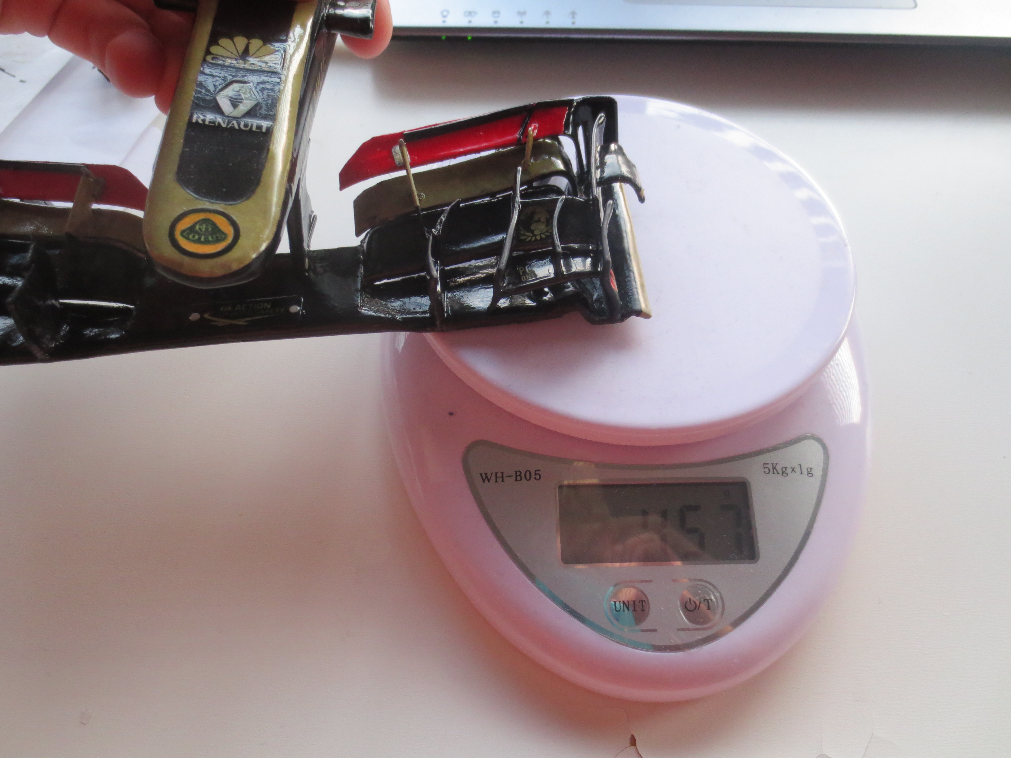
In general I'm very satisfied with the result of the FW. The surface quality could be a bit better in some places. But that's more a problem with restricted access as it's like under the small Front Flaps. The FW-Nose Assembly is with 49g pretty heavy. That's about 8.5% of the car weight. As you can see on a picture below, the stiffness of the wing is incredible. I did a simple deflection test where the wing resisted over 500g load which would be equivalent to 500kg(!) at the real car. I didn't measured any deflection of the wing, but the regs are telling you, that the wing should not deflect more than 10mm at a load of 100kgs. Maybe I do a proper deflection test on a rig somewhen. Just for fun (This statement is a bit sensless considering this is my hobby and should be fun all time).
Anyway, except a few dimension overrides conflicting with the front bodywork regulations, I'm pretty pleased with my new Front Wing. I hope the guys from Lotus are too.
Start of the Front Wing Main Aerofoil. At the top you can see the main insert, which is actually just an offset of the aero surface. The tube in the middle is a paper wrapped 1.2mm steel wire (which you usually use to build fences) which gives the Main Aerofoil the needed bending stiffness around the X-Axis. The front insert is the connection between wing and Nose Pylons. This design secures, that the flexibility between the nose and the wing is reduced to a minimum, which was a huge problem on my RB7 where the connection was very groggy...
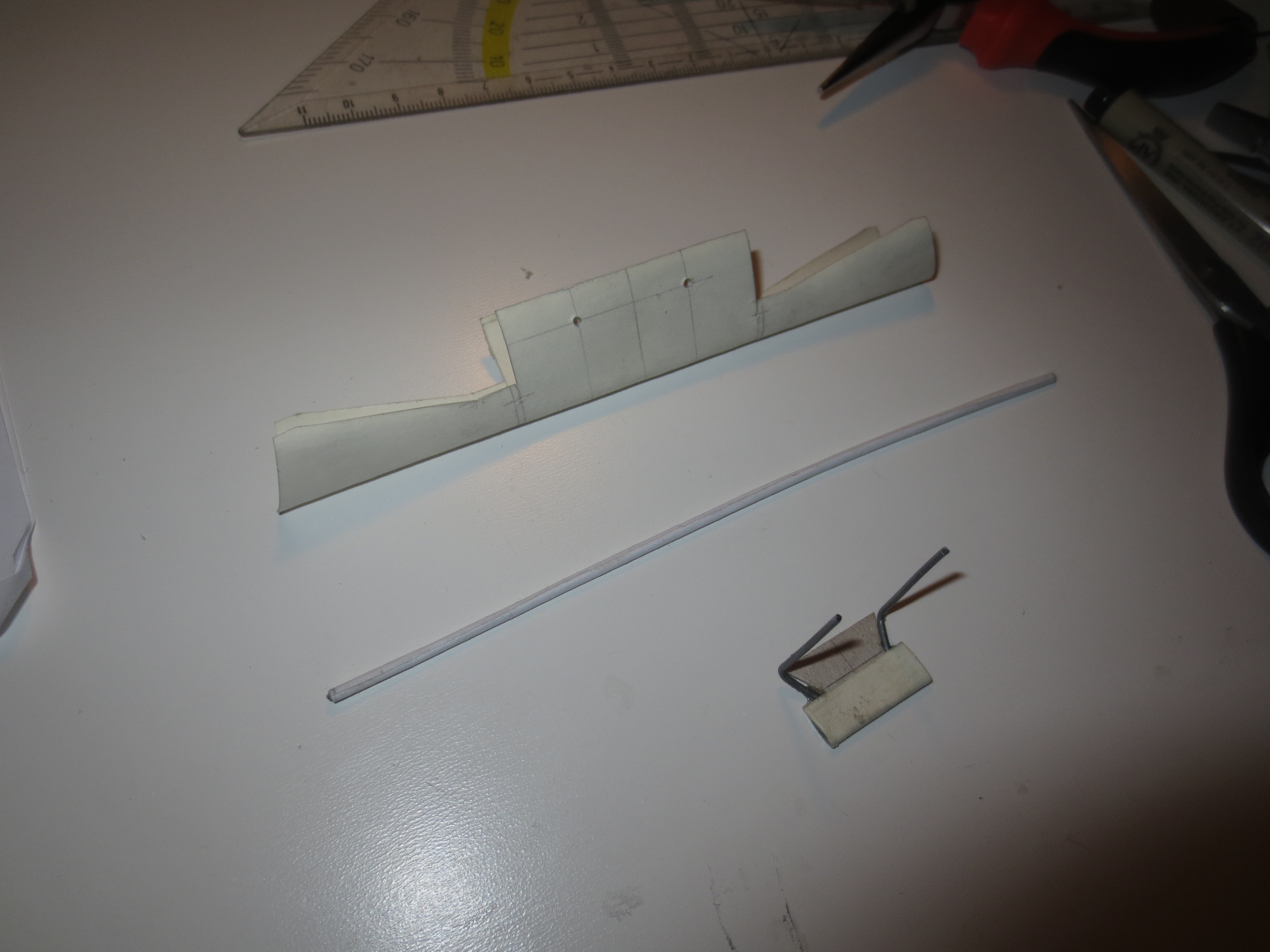
Here you can see the bonded in inserts in the FIA section of the Main Aerofoil. There are more inserts to come outside of the 500mm FIA middle section. The secondary flap on the Main Aerofoil, which is behind the forward aerofoil profile is later also reinforced with a steel wire. For this, I had to provide two additional circular holes in the rearward inserts.
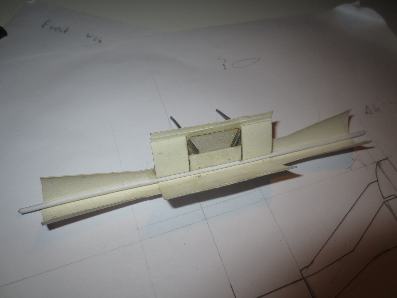
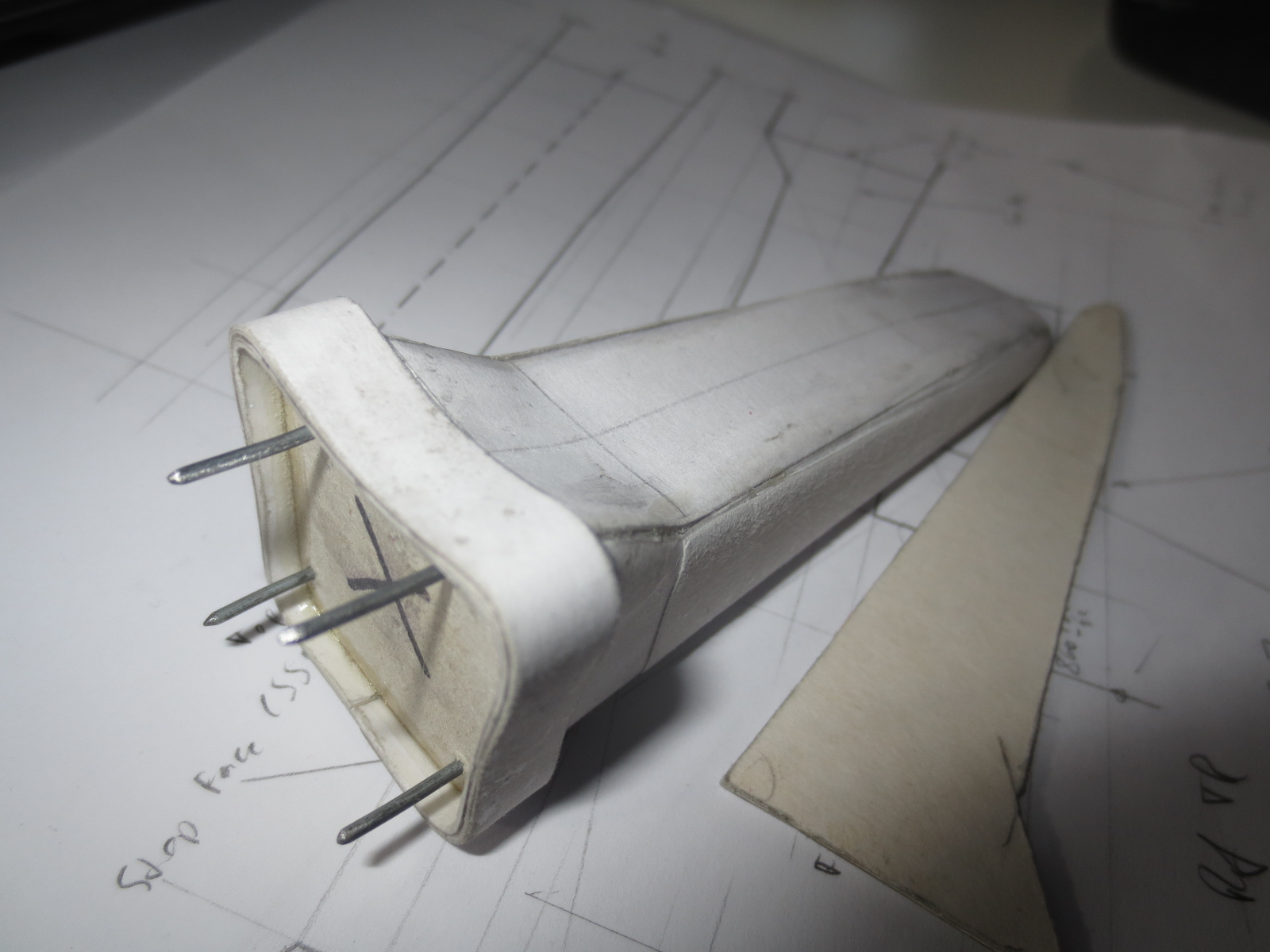
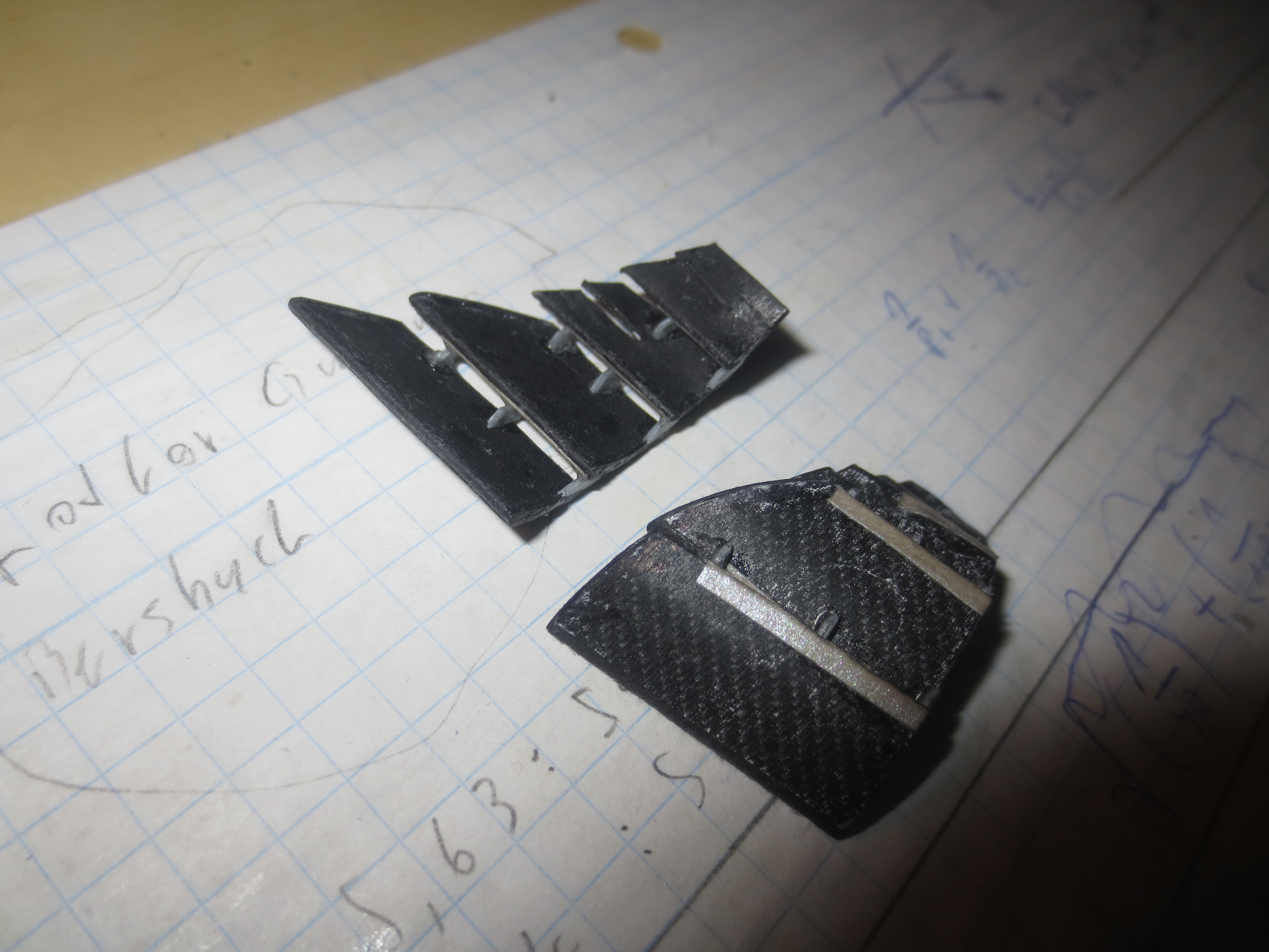
The Front Wing End Plates (FWEP) at the start stage. There are two inserts in it. You can see both of them in the endplate at the top of the picture. These inserts should secure, that the FWEPs have nice sharp trailing edges as well as nicely rounded leading edges all over the part.
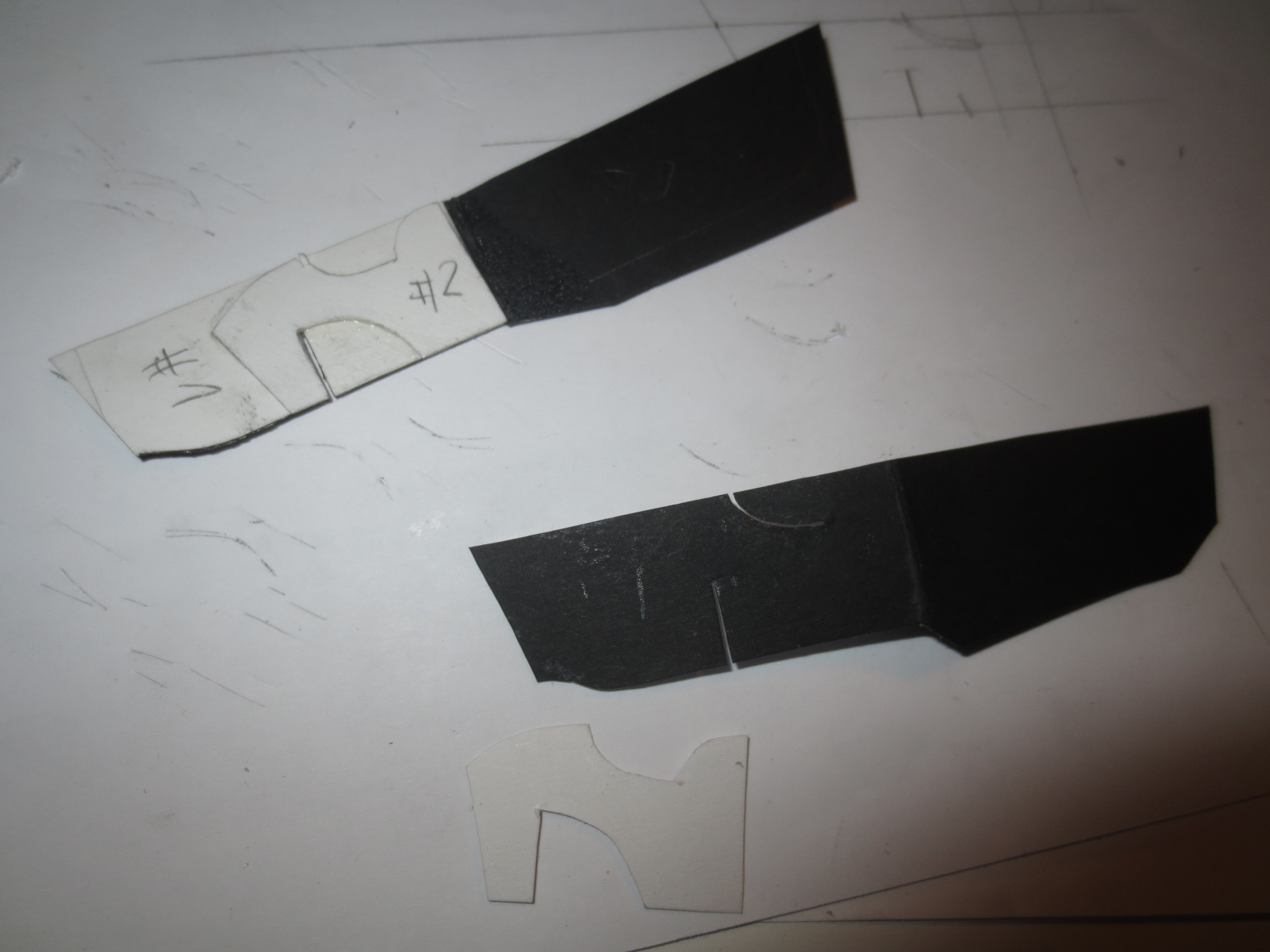
From the laminate point of view, the front wing Main Aerofoil is probably the most impressive element on a F1 car. As you can see in this pic, and believe me, I did the laminate exactly like it is at the real car, the layup is pretty complex. That's alyways a nice exercise for the stress guys.
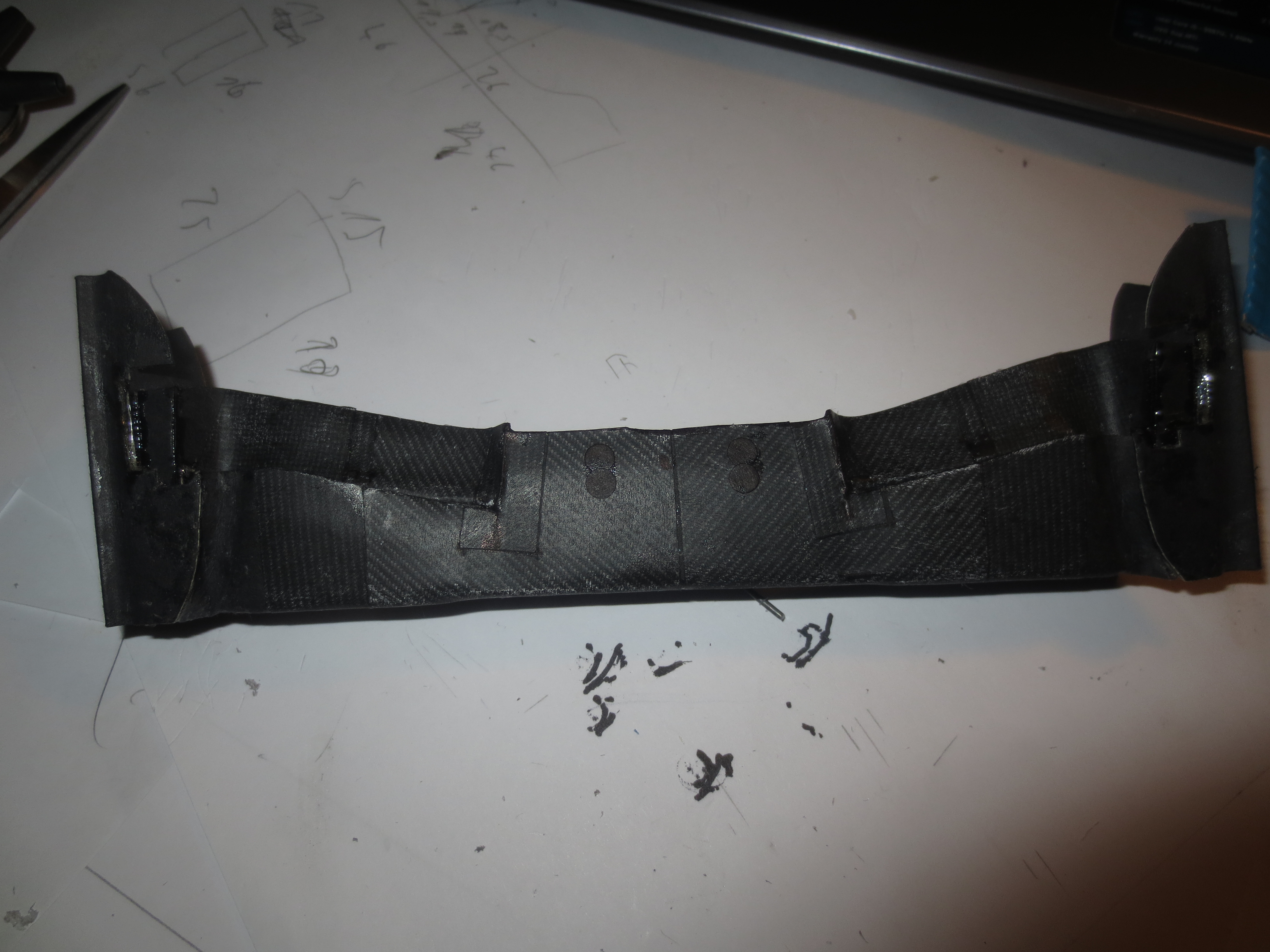
The first flap is bonded to the FWEP. This flaps are a little bit too long in terms of regulations (something around 1mm), so they protrude into the 500mm middle section - looks like Lotus is cheating (I can't be wrong, can I?). :p
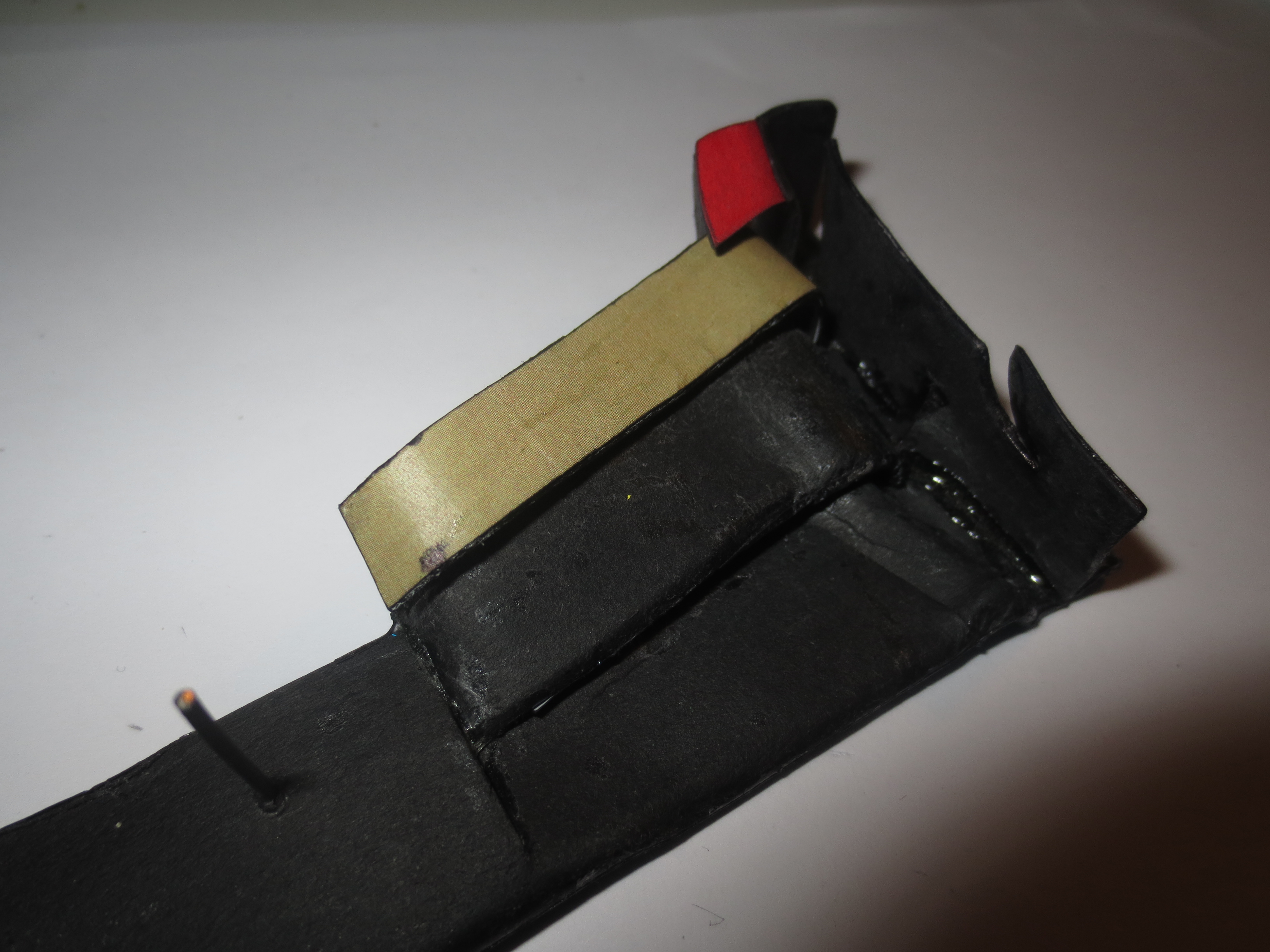
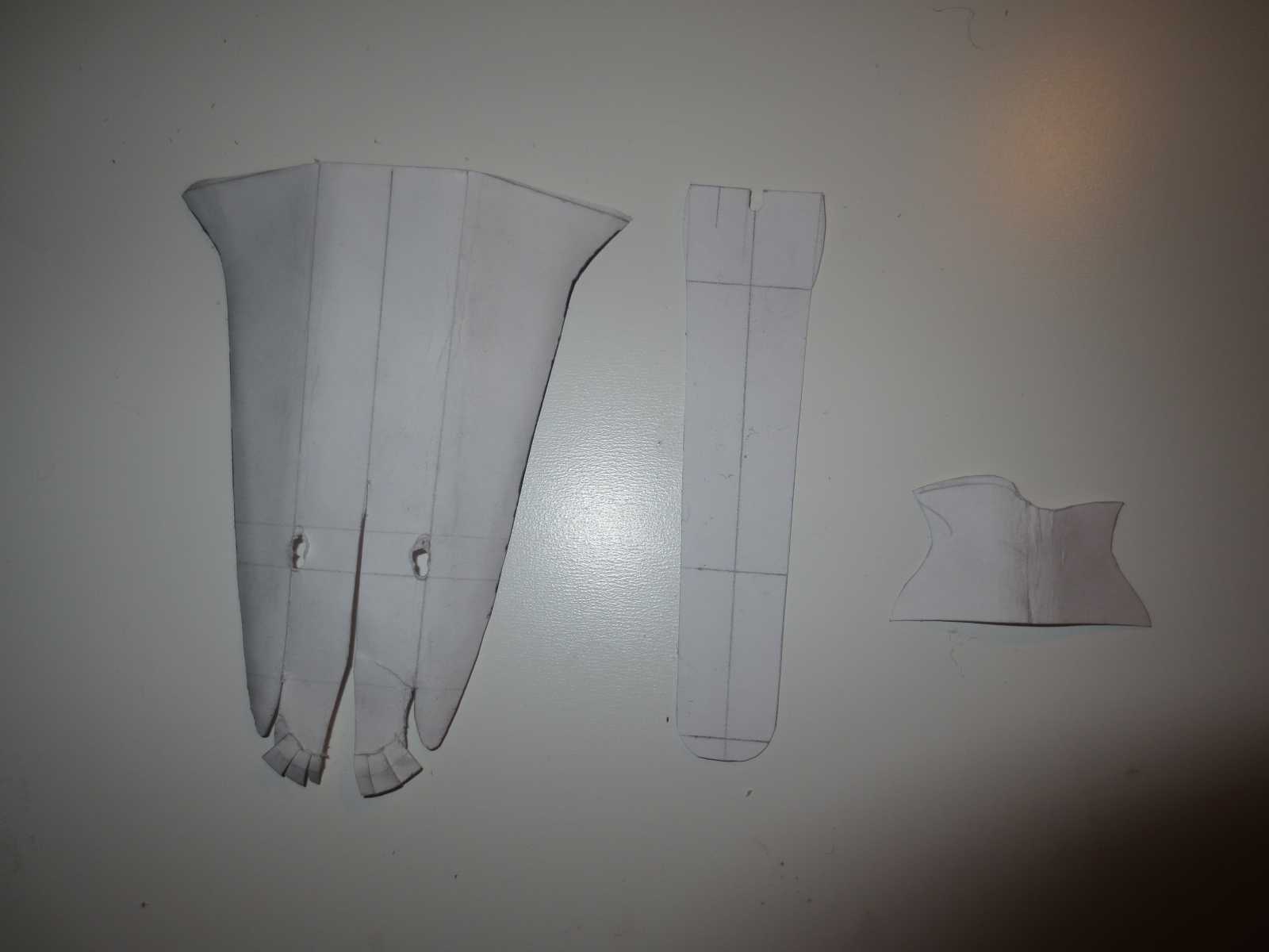
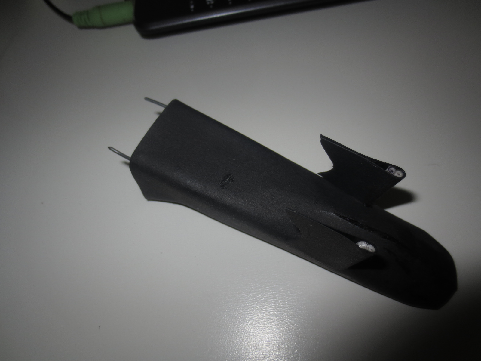
These small flaps are good fun to do. Very simple shapes, but they are looking pretty nice. These flaps are also varying a very lot from team to team. The Lotus ones have already nothing to do with the RB ones.
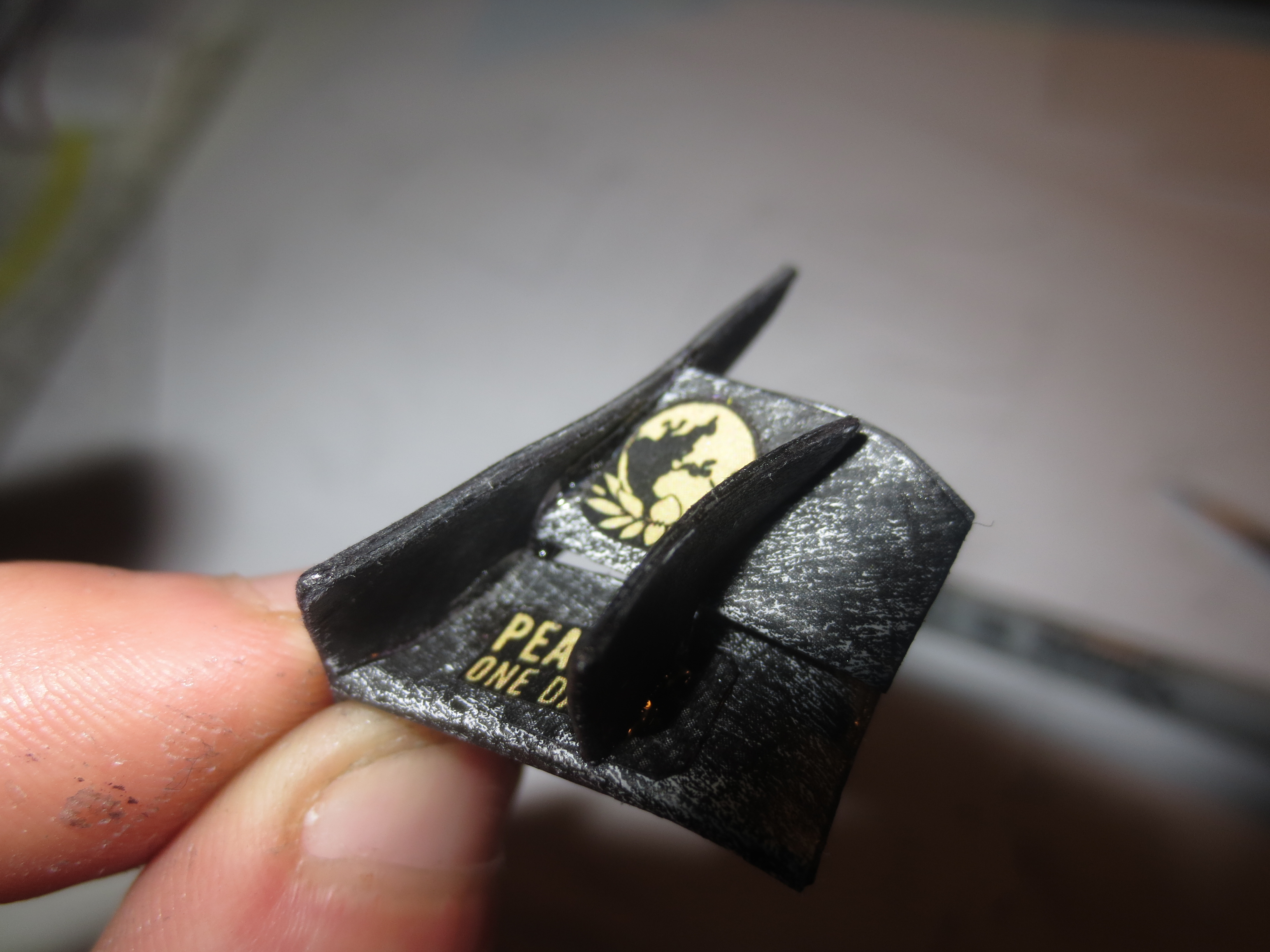
Here you can see the flap adjuster where you can quickly adjust the wing in the box or even during a pit stop. Beside the DRS flap, this is the simplest thing on the car to change aero balance.
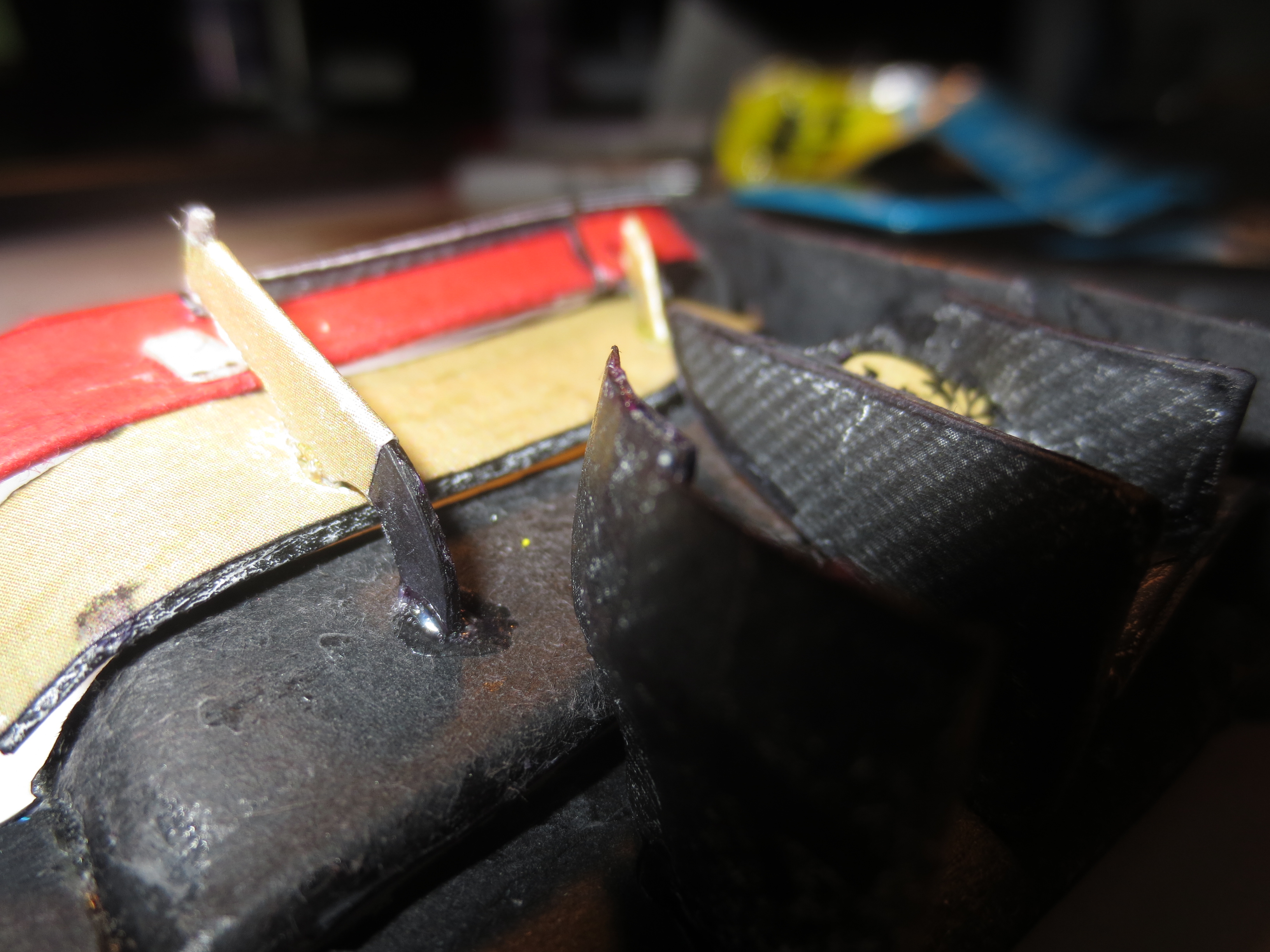
The outboard flap hanger which secures, that the slot gap between the single flaps stays almost constant. On this pic, you can also see the gurneys pretty good. Design gurneys for a real car isn't very exciting and it's pretty much --- when you have to do it in 1:10 scale. But if you're designing a wing, it happens that you also have to design the gurneys.
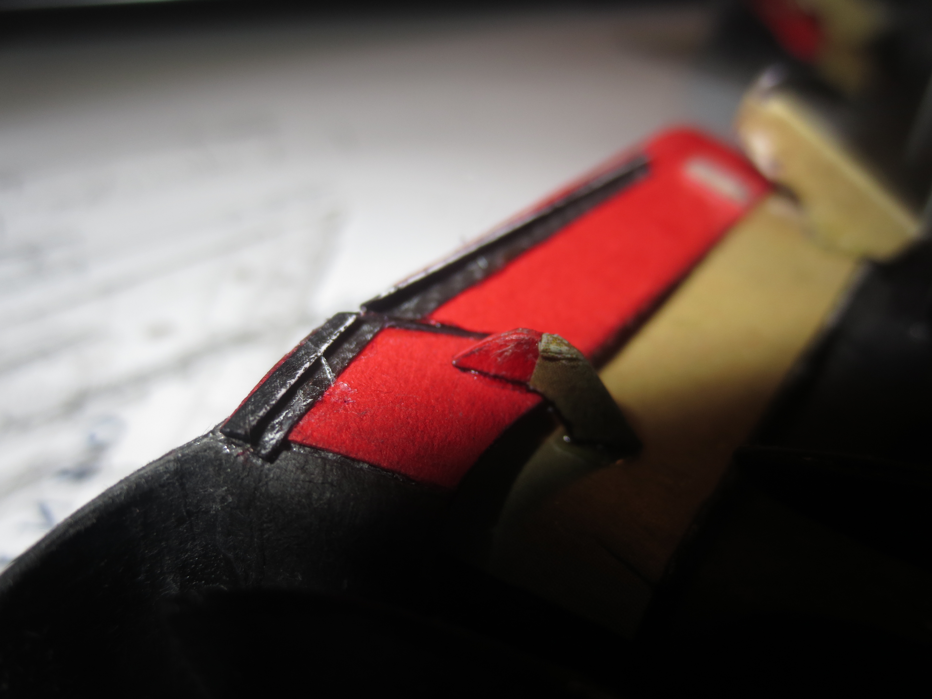
The underside of the full assembly. Notice the very funky swept inboard strakes. Also noticeable is the trailing edge of the FWEP which ends up being 90° to the X-Axis.
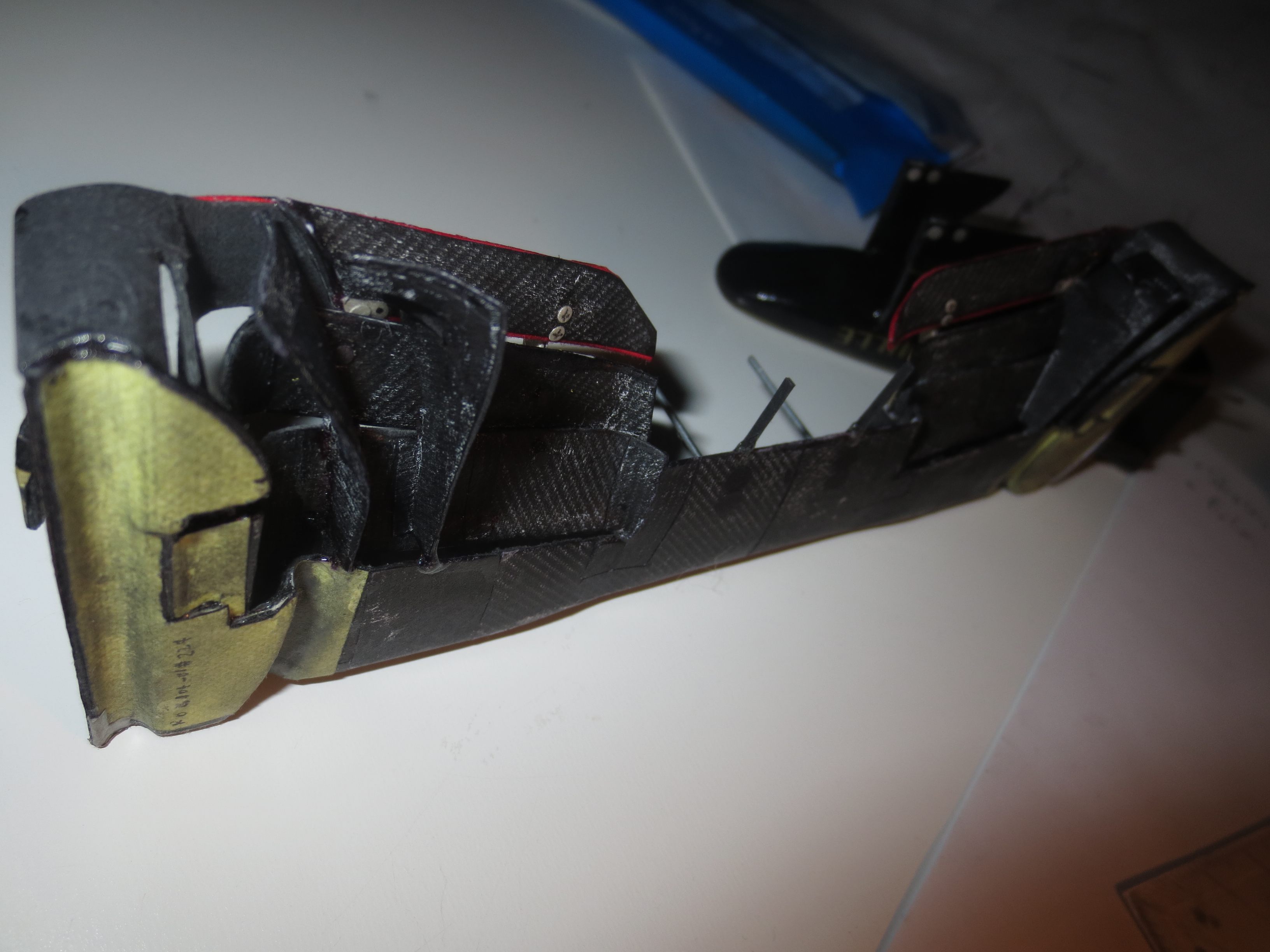
The front wing deflection test. The wing wasn't even bonded to the nose that time. As stated above, I haven't measured the deflection. But more than 500g load, which is equal to about 0.33Nm at the pylon mounting point, is pretty impressive for a paperwing. Next evolution of Boeing and Airbus will the the invention of cardboard wing flaps.

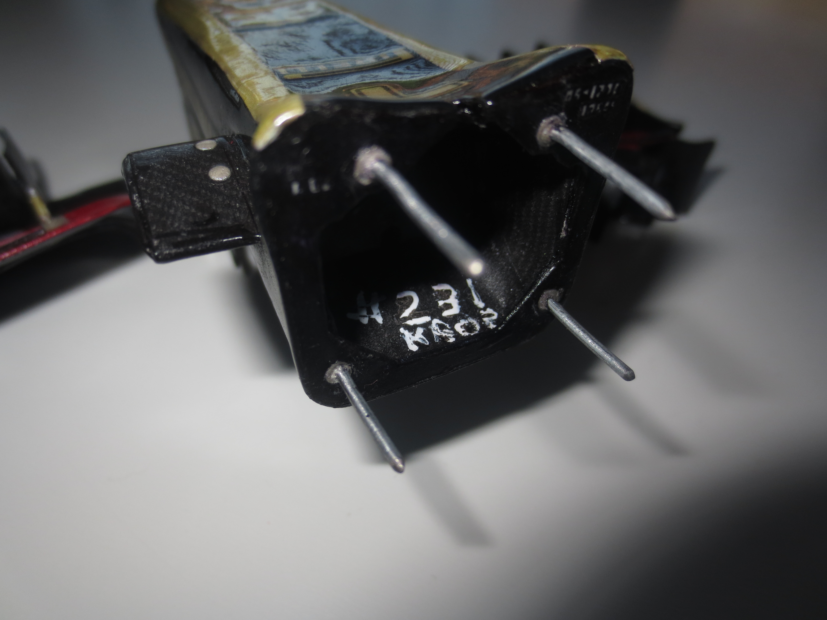
A look inside of the nose. The Nose Pins are pretty long. I will probably shorten them when the car is finished.
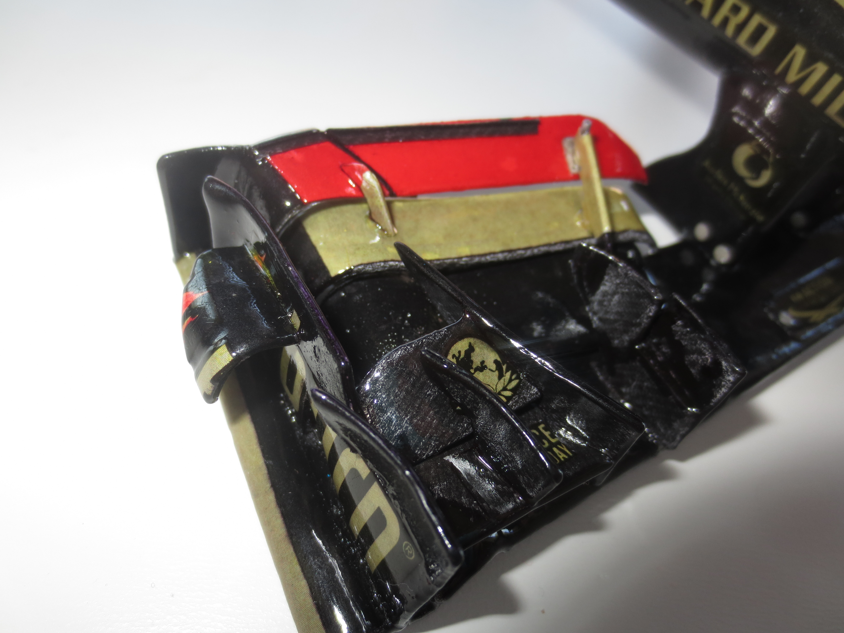
A Top front view onto the outer Front Wing. It's just a masterpiece of aerodynamic art. As I'm no aerodynamicist, I'm always impressed about the creativity of the F1 aero engineers.
Top rear view onto the outer Front Wing.
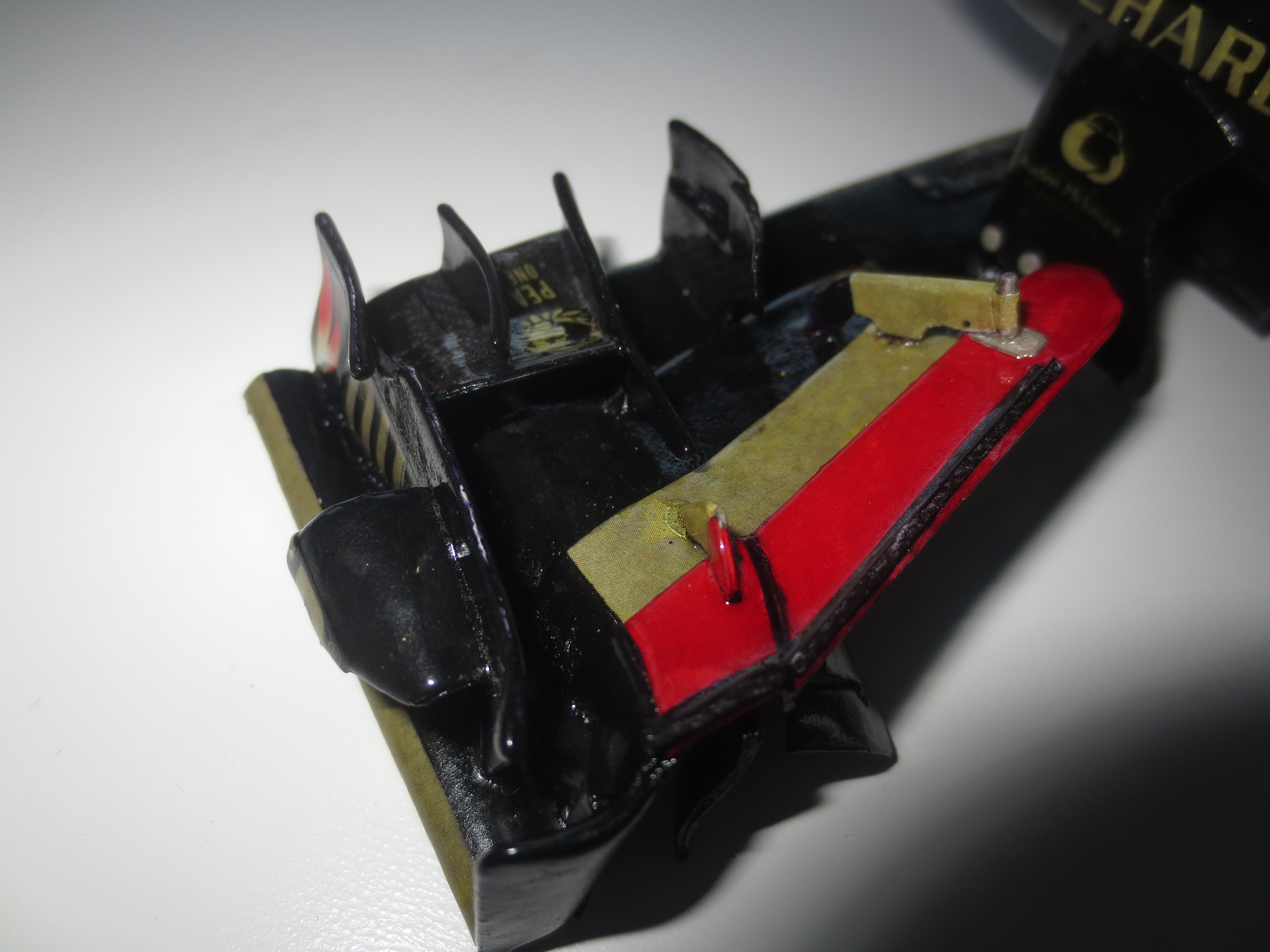
A few years ago, the Front Wing End Plates were just sipmle flat plates which only had to close off the wing. It's obvious and visible that that's not the only task for them nowadays.
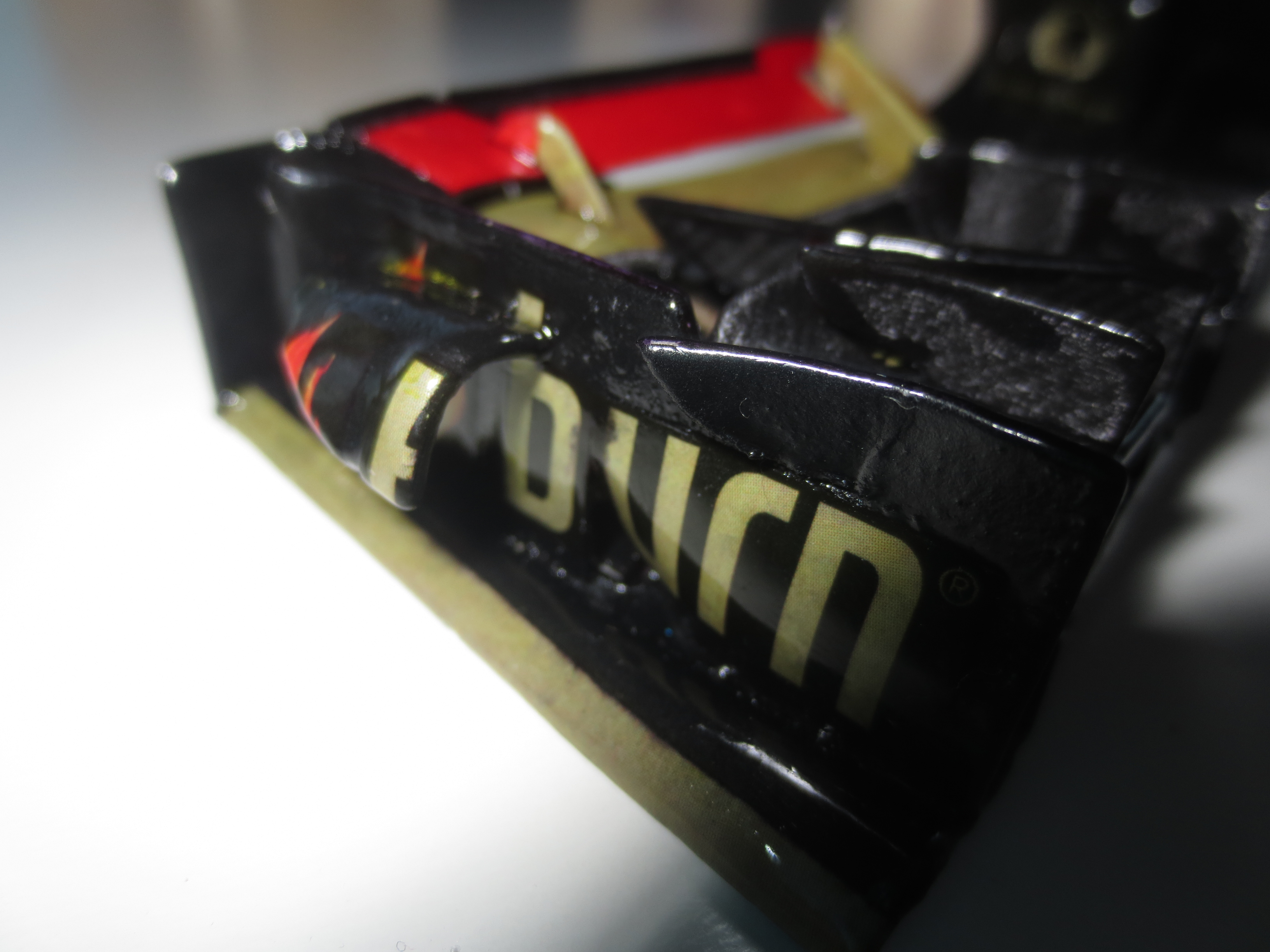
The underside of the outer Front Wing. At the outer few mm you can see the glass fibre which is required by the regulations. At the very front outer edge you can also see a skid block, probably from Ti, to safe the wing from damage caused by grounding.

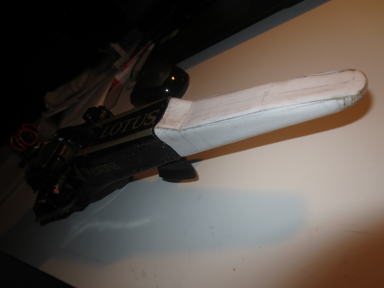
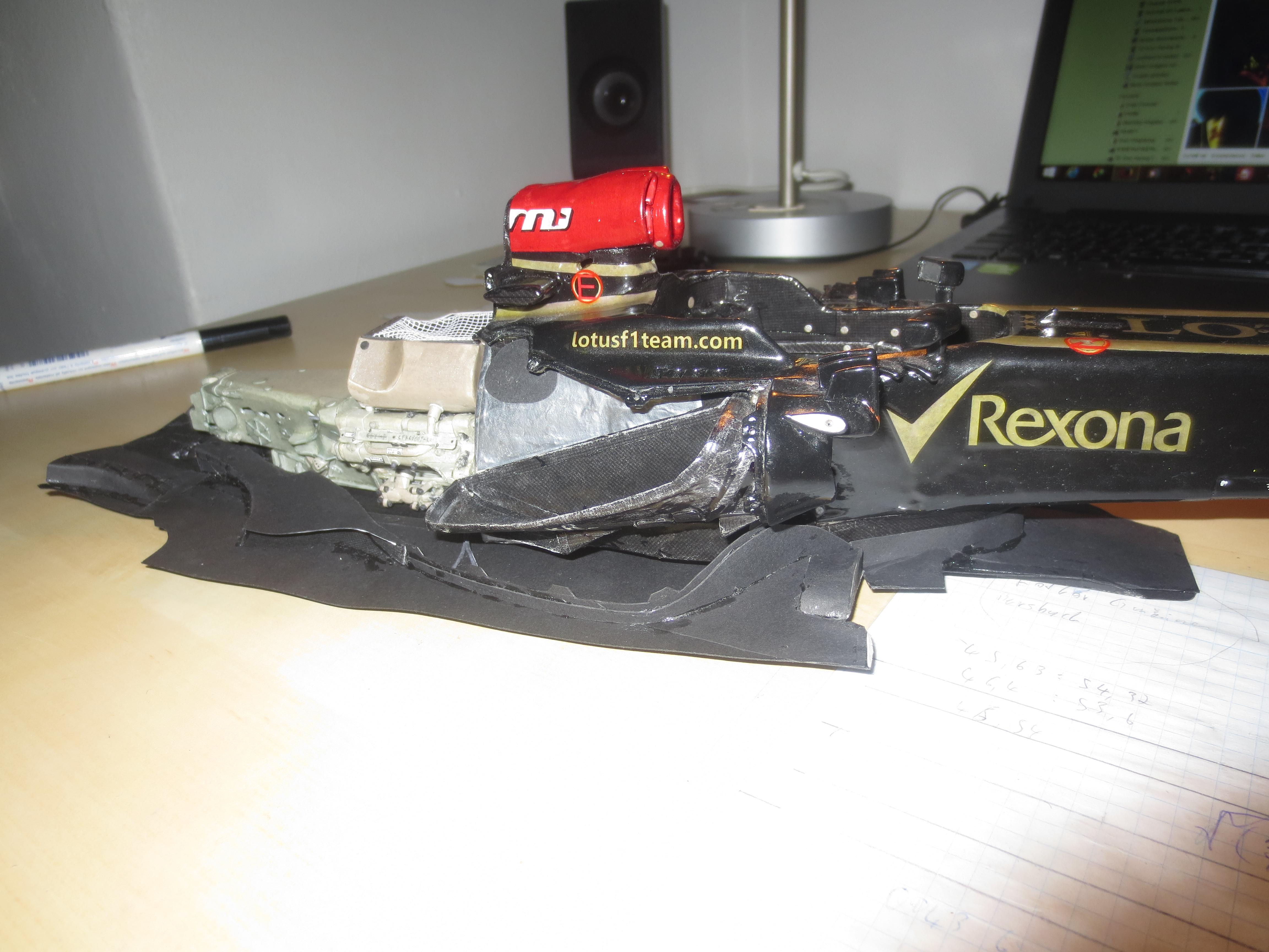
Nose assembled to the chassis.
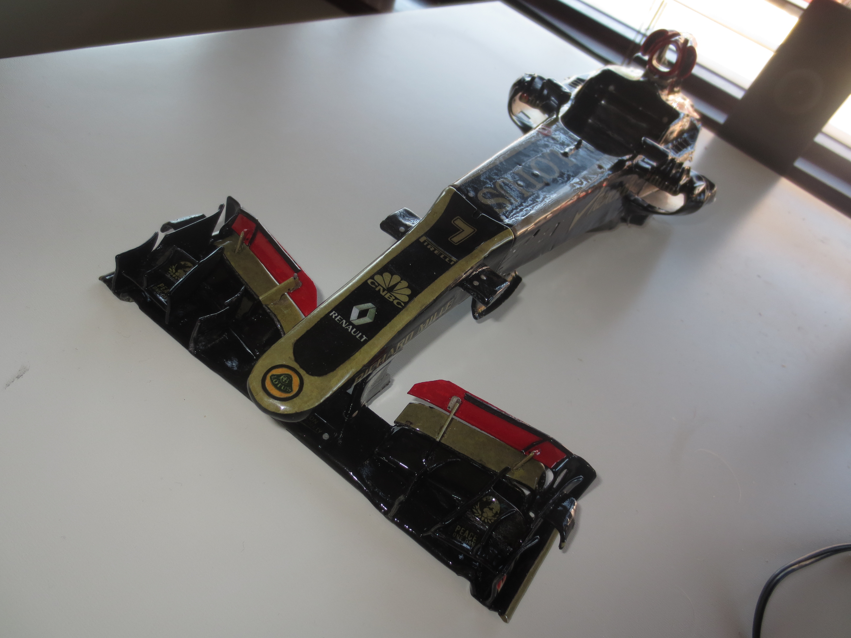
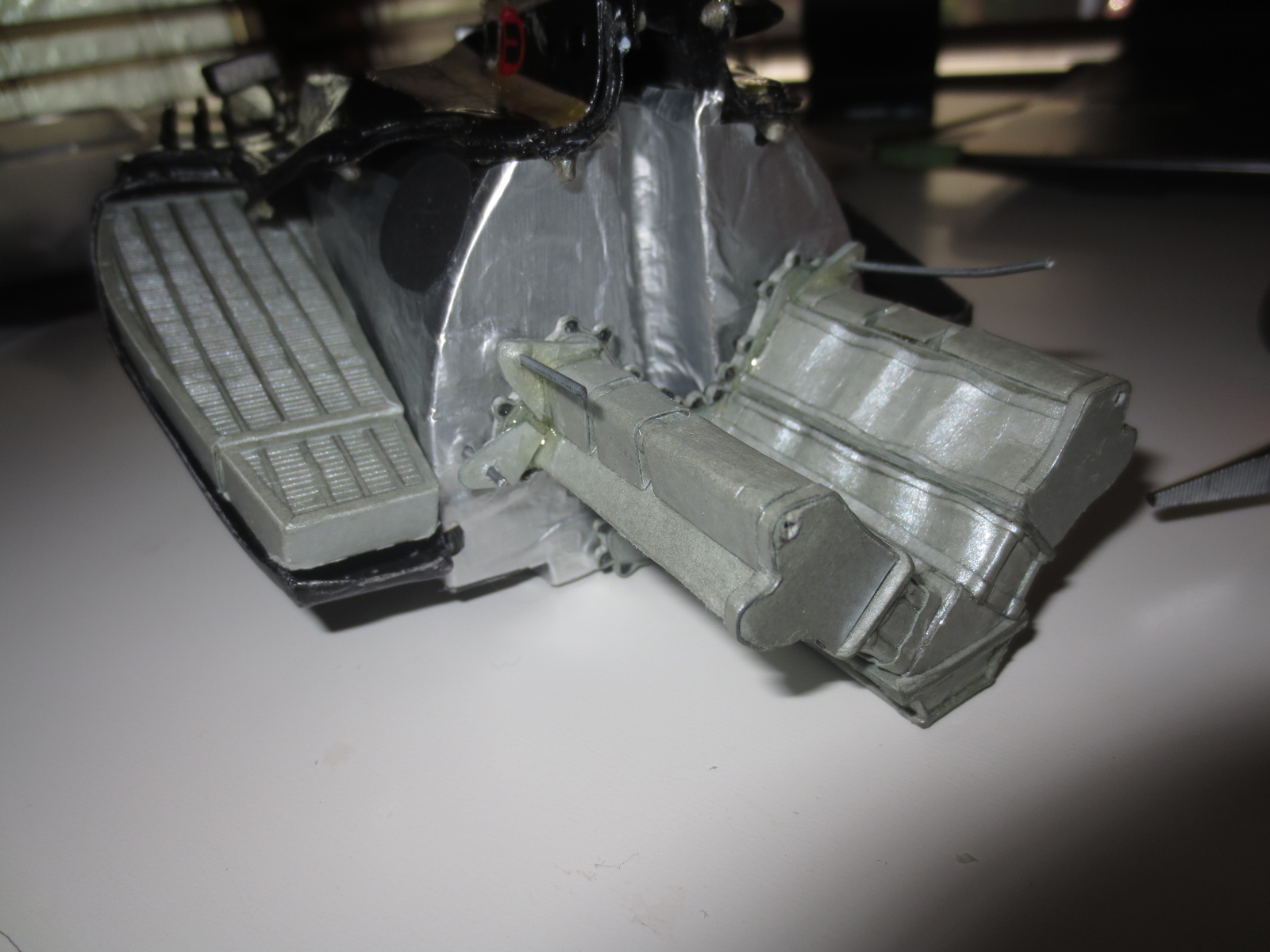
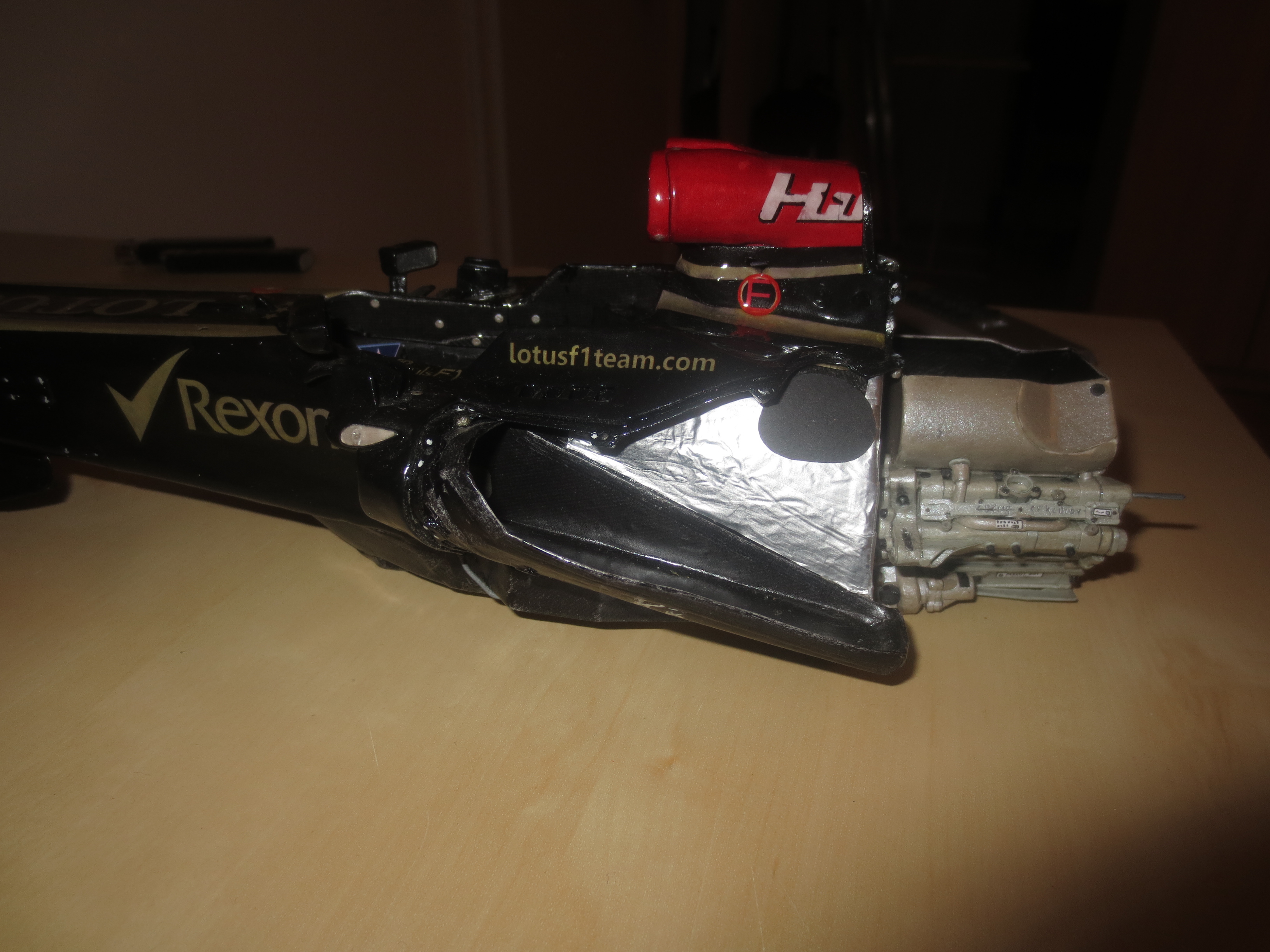
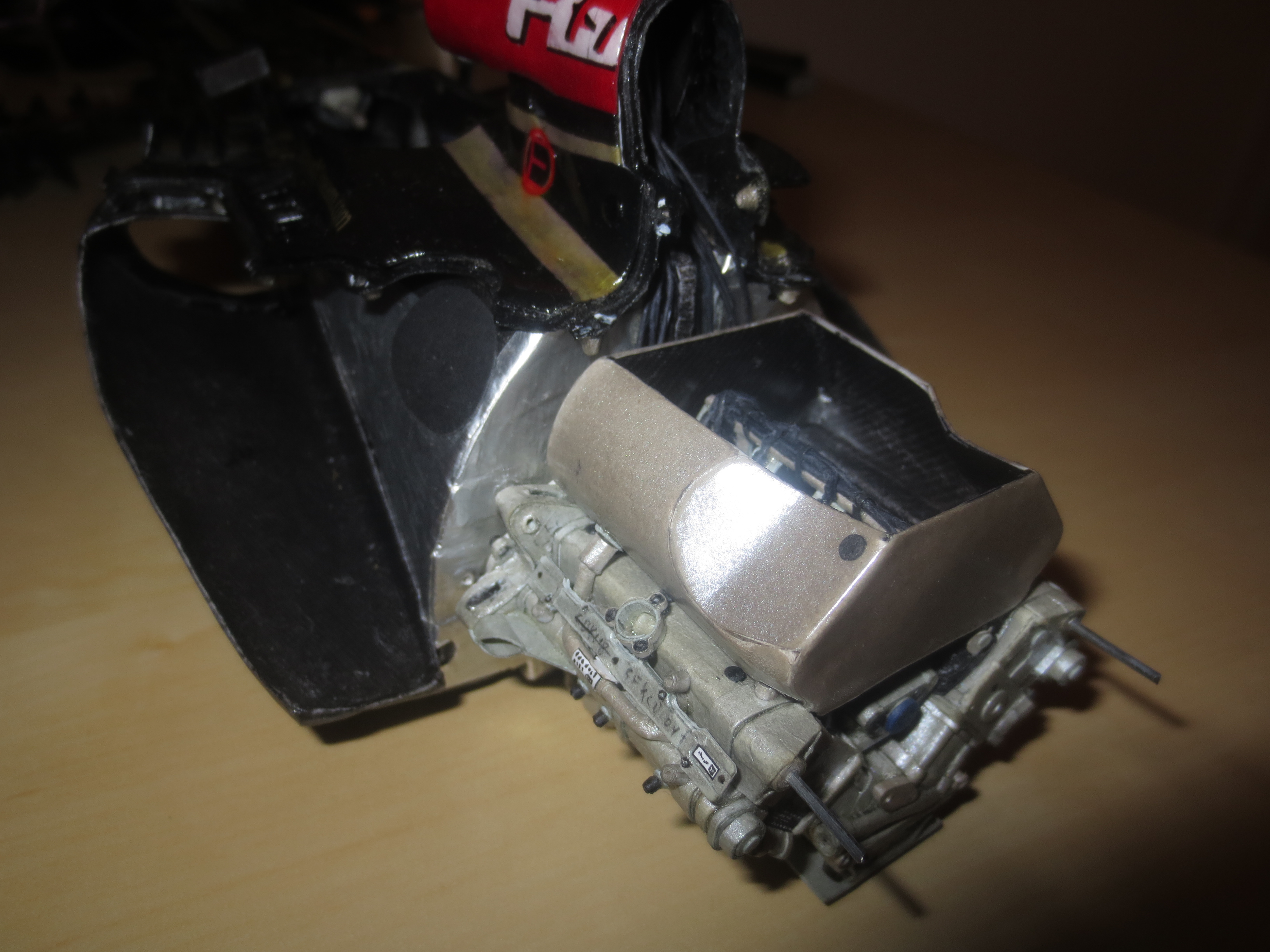
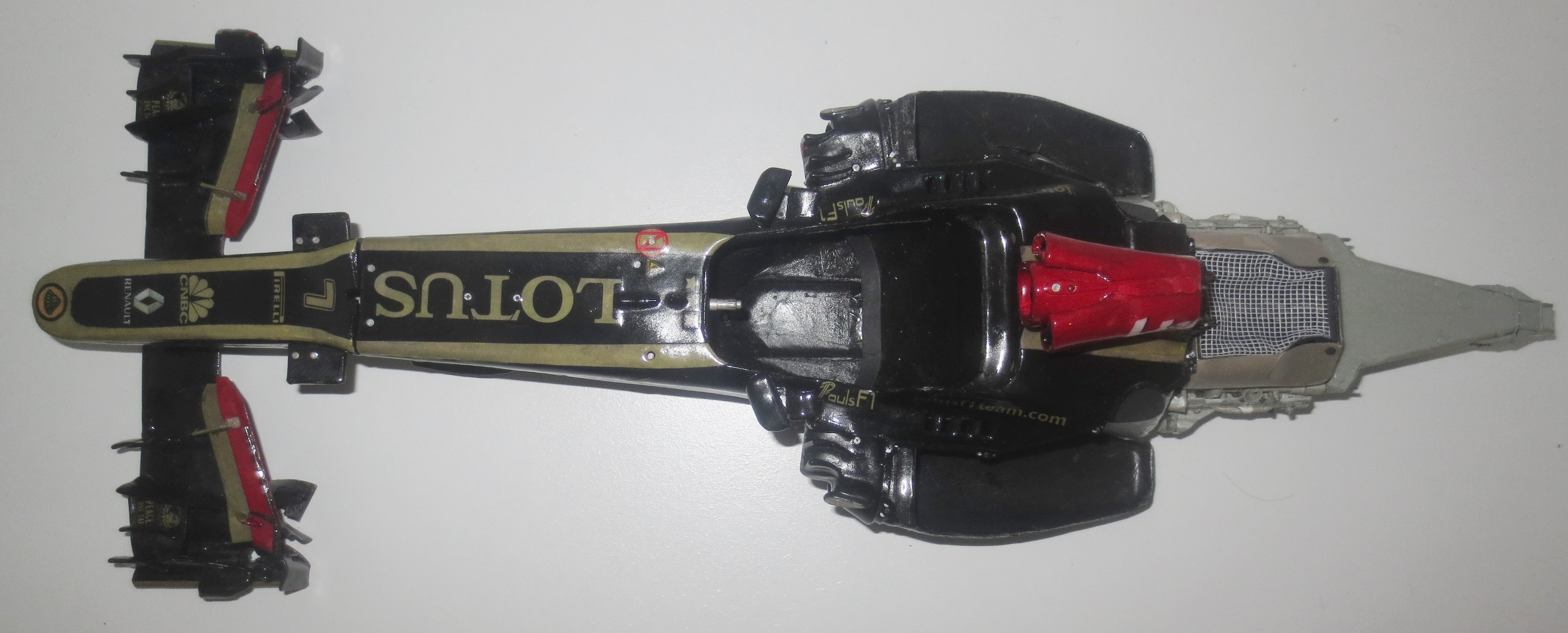
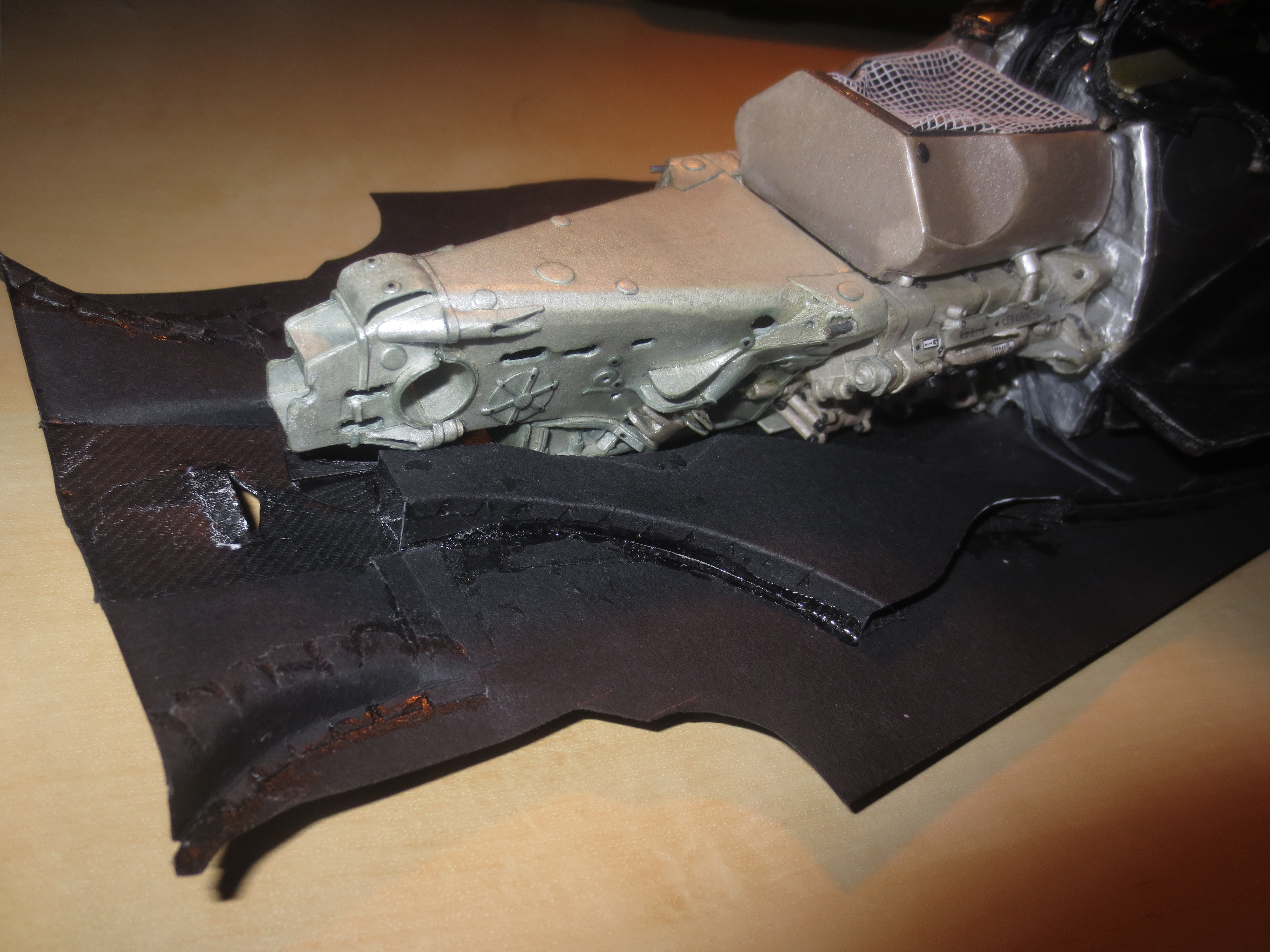
Front Wing in front of the Monocoque and the engine block.
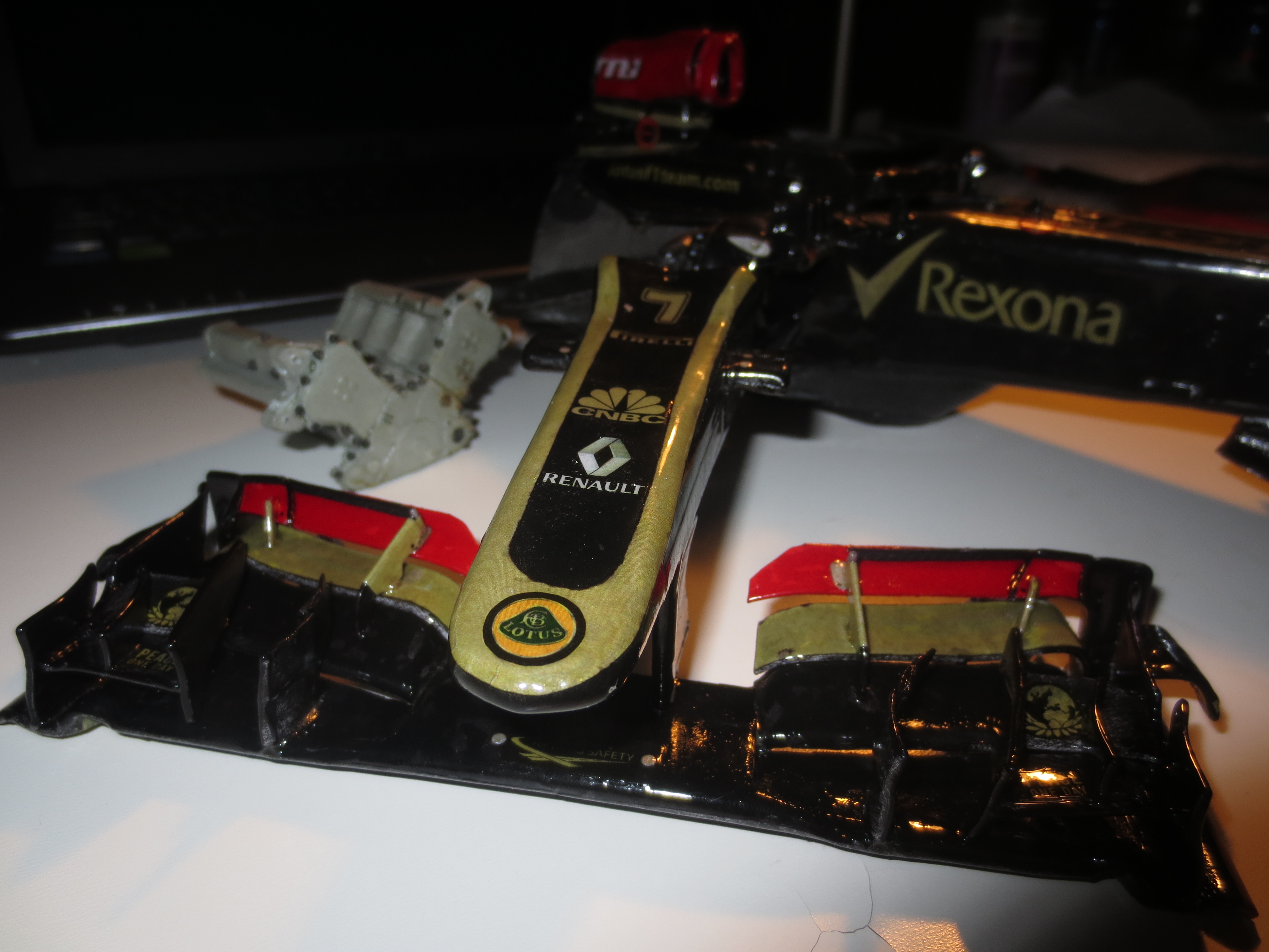
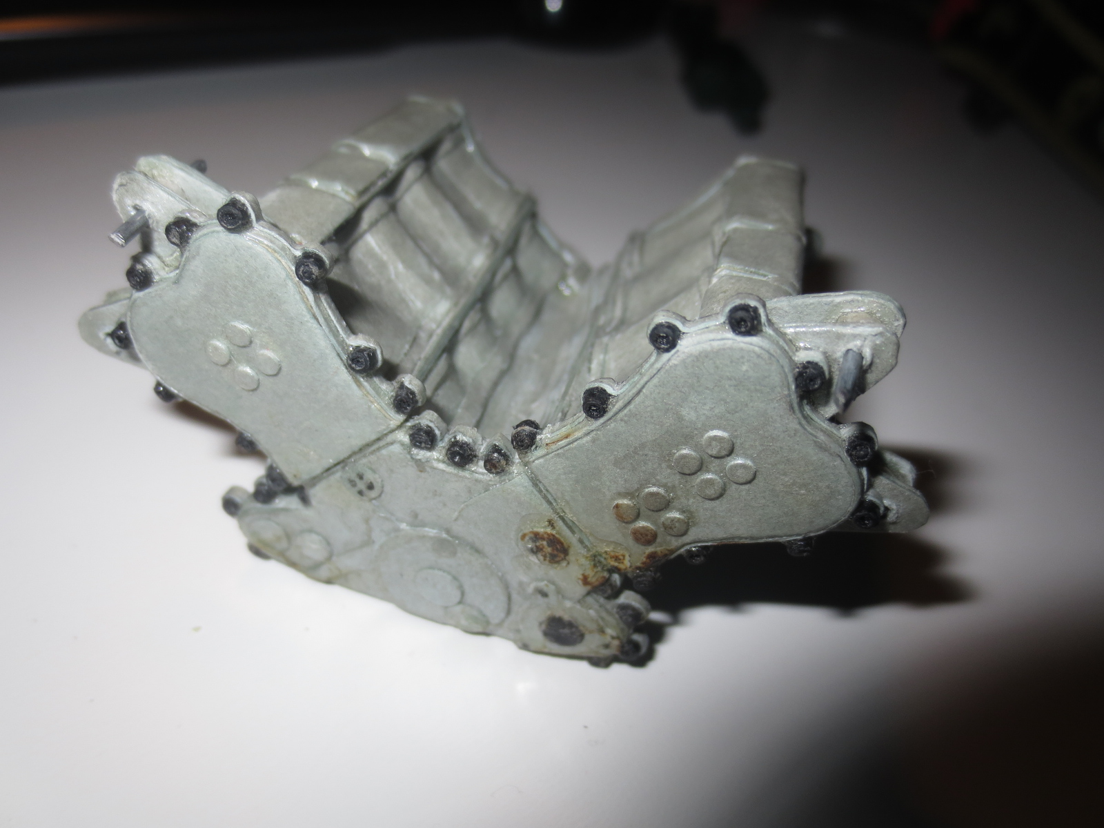
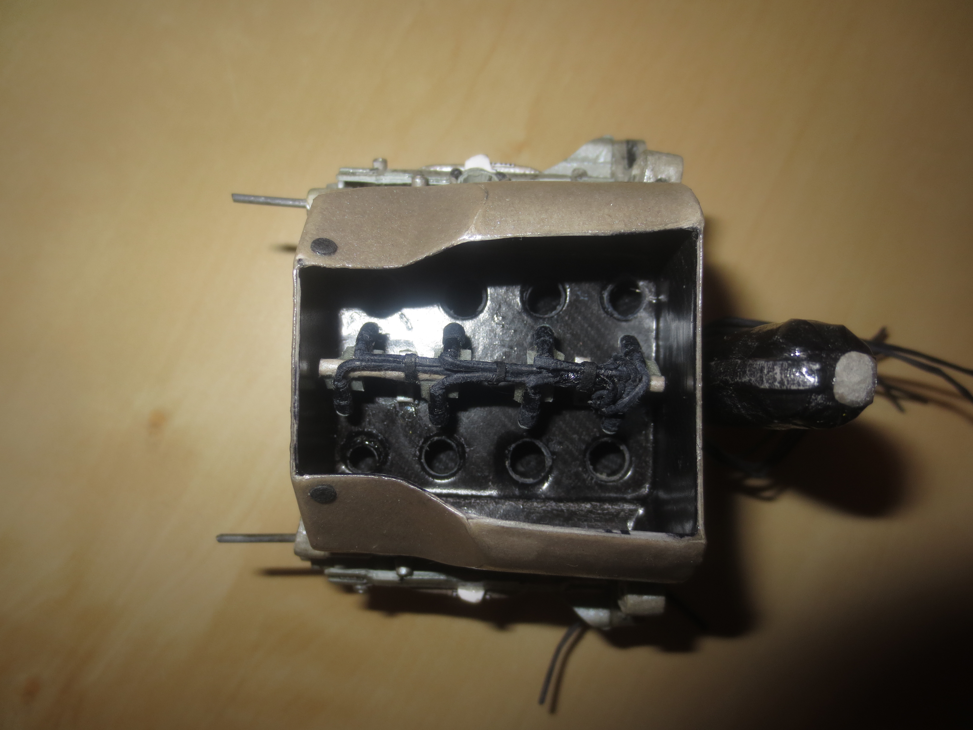
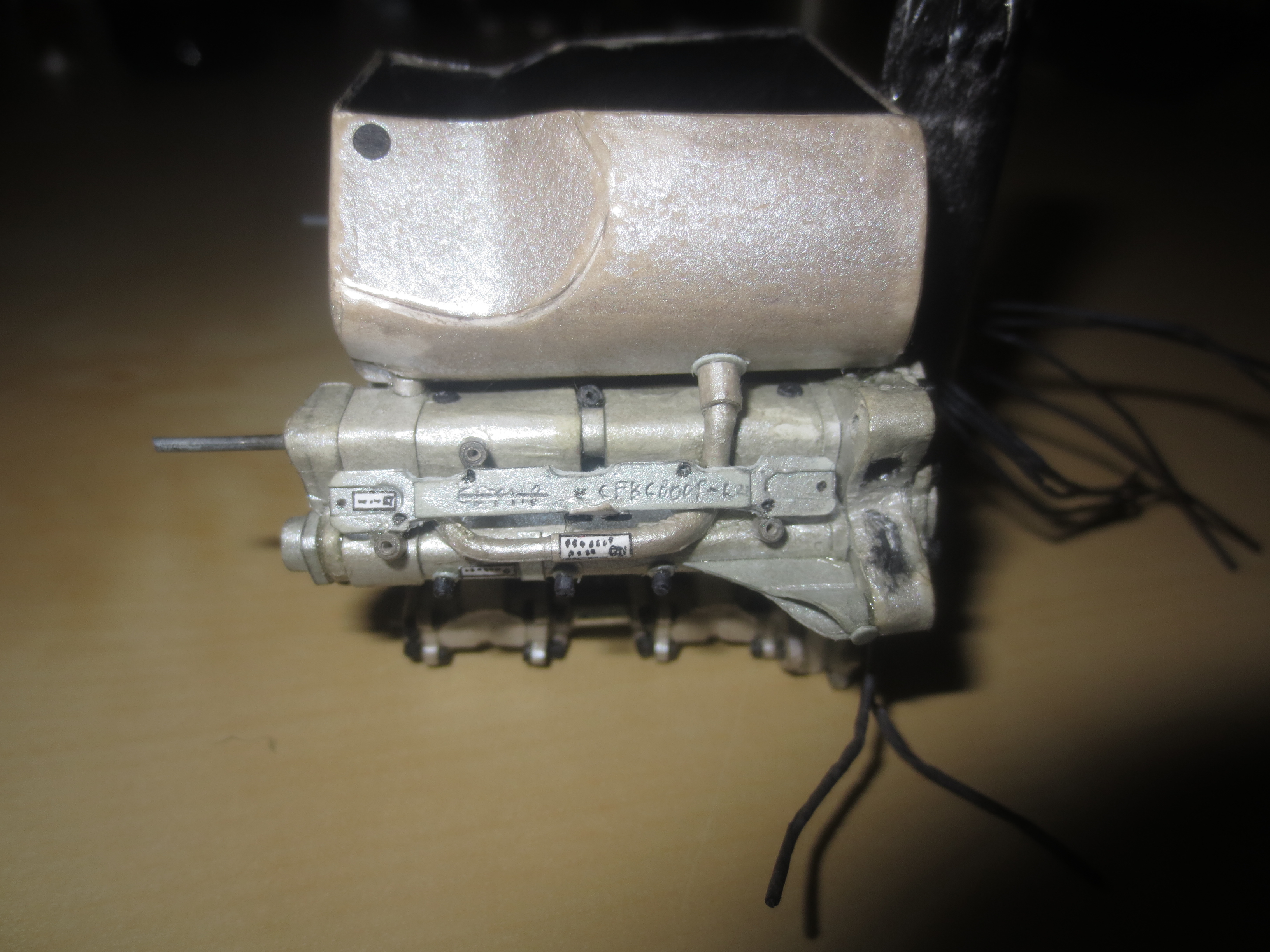
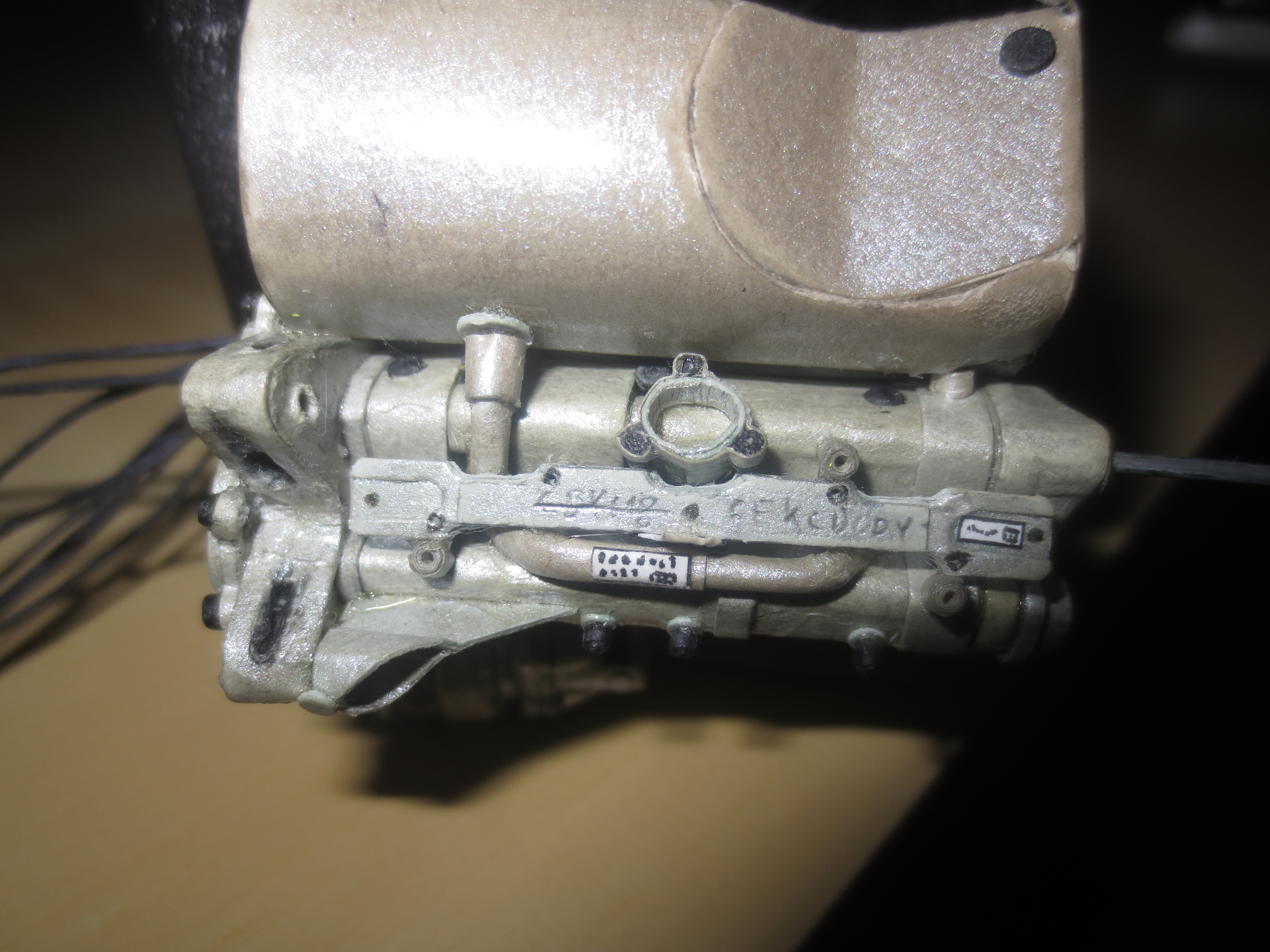
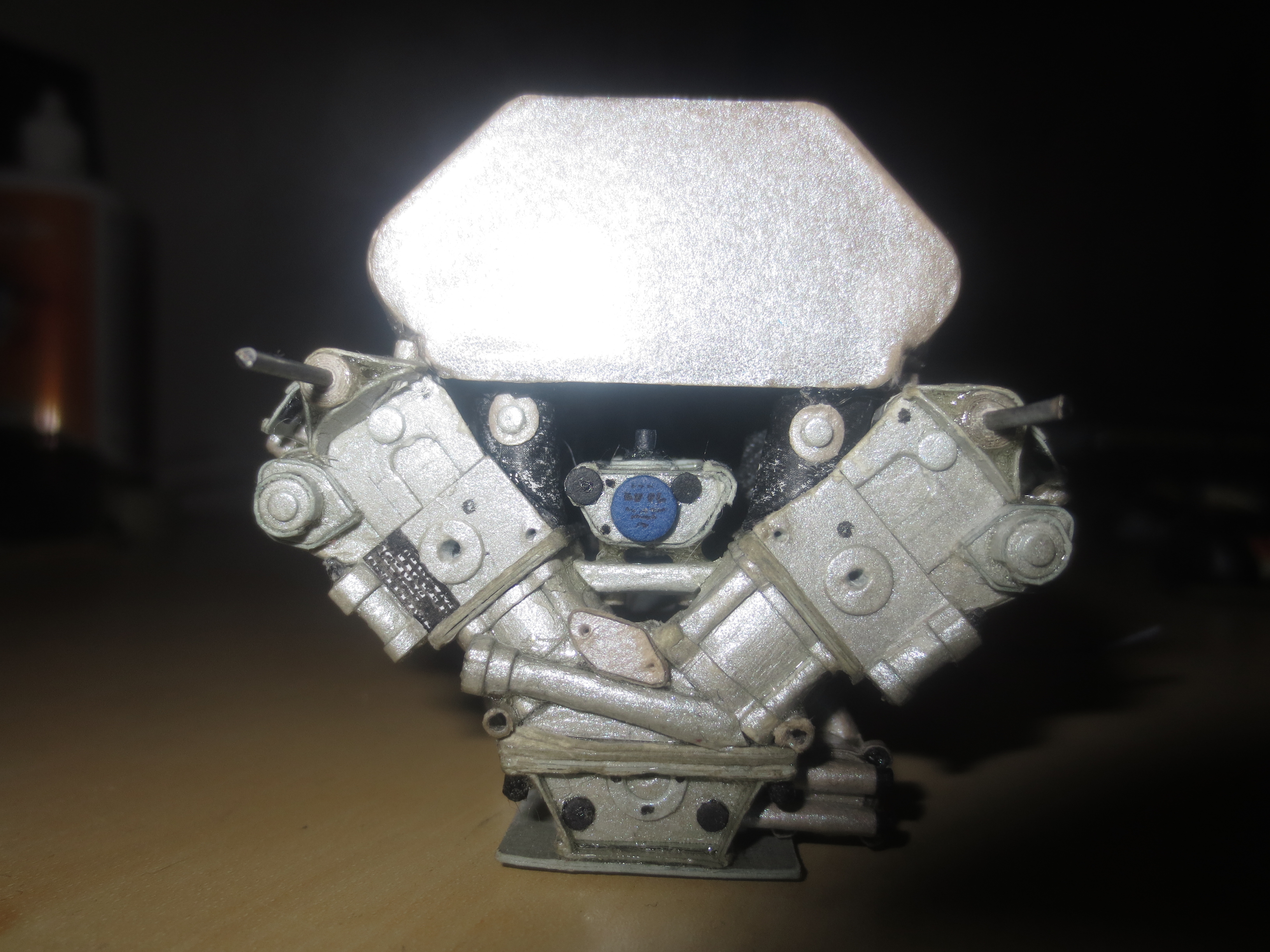
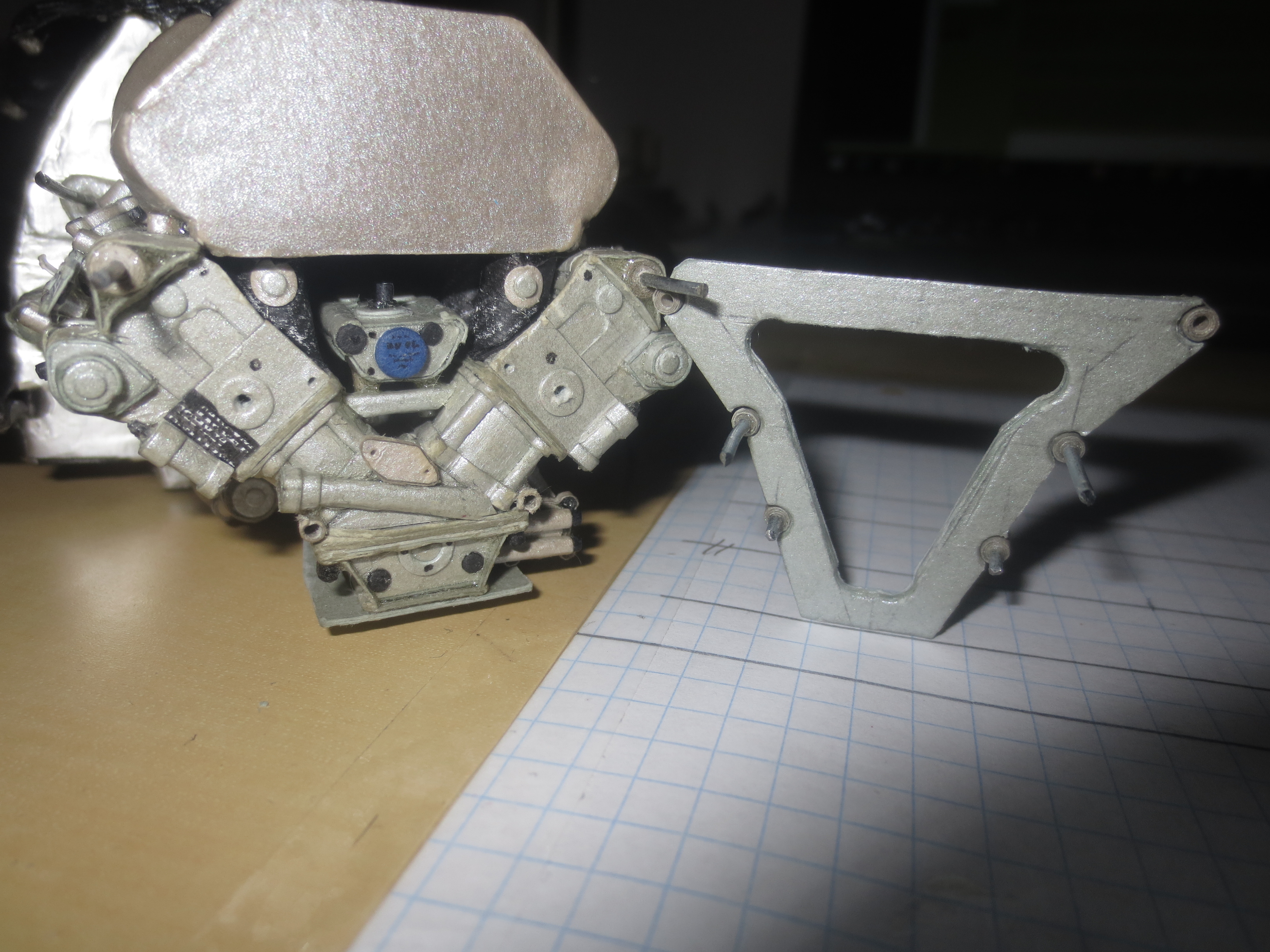
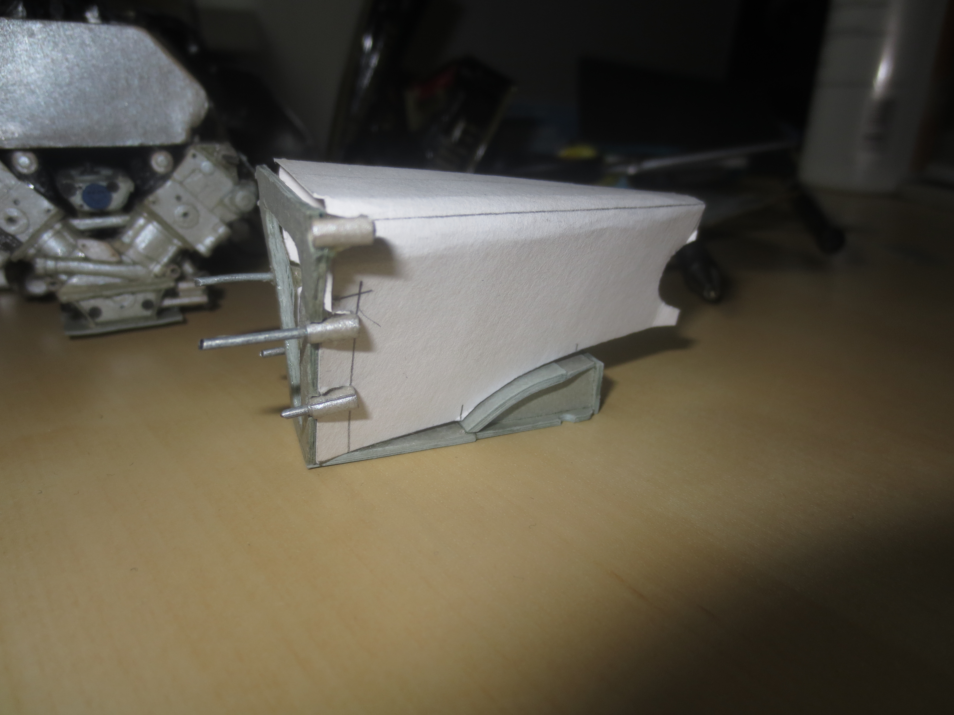
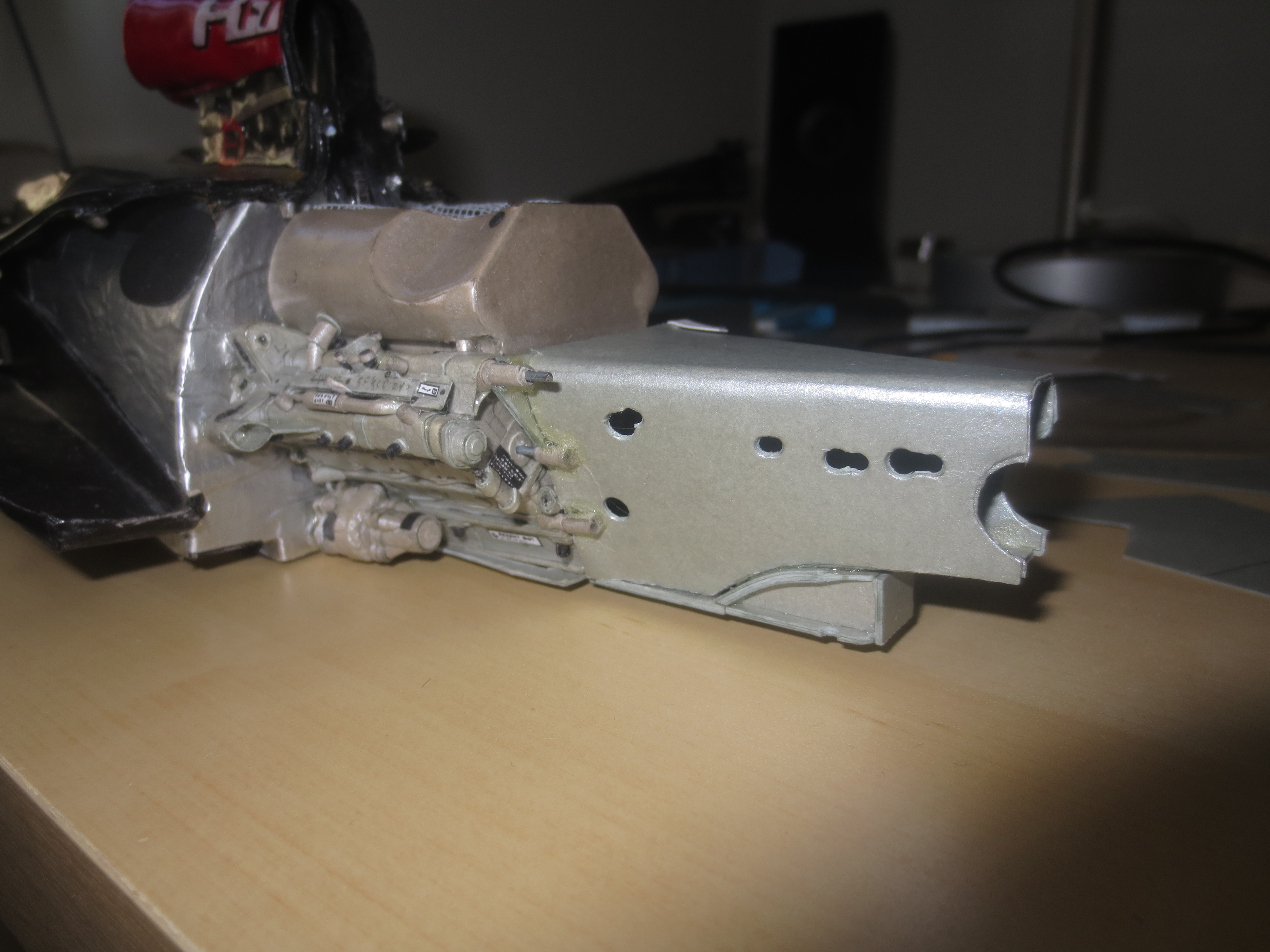
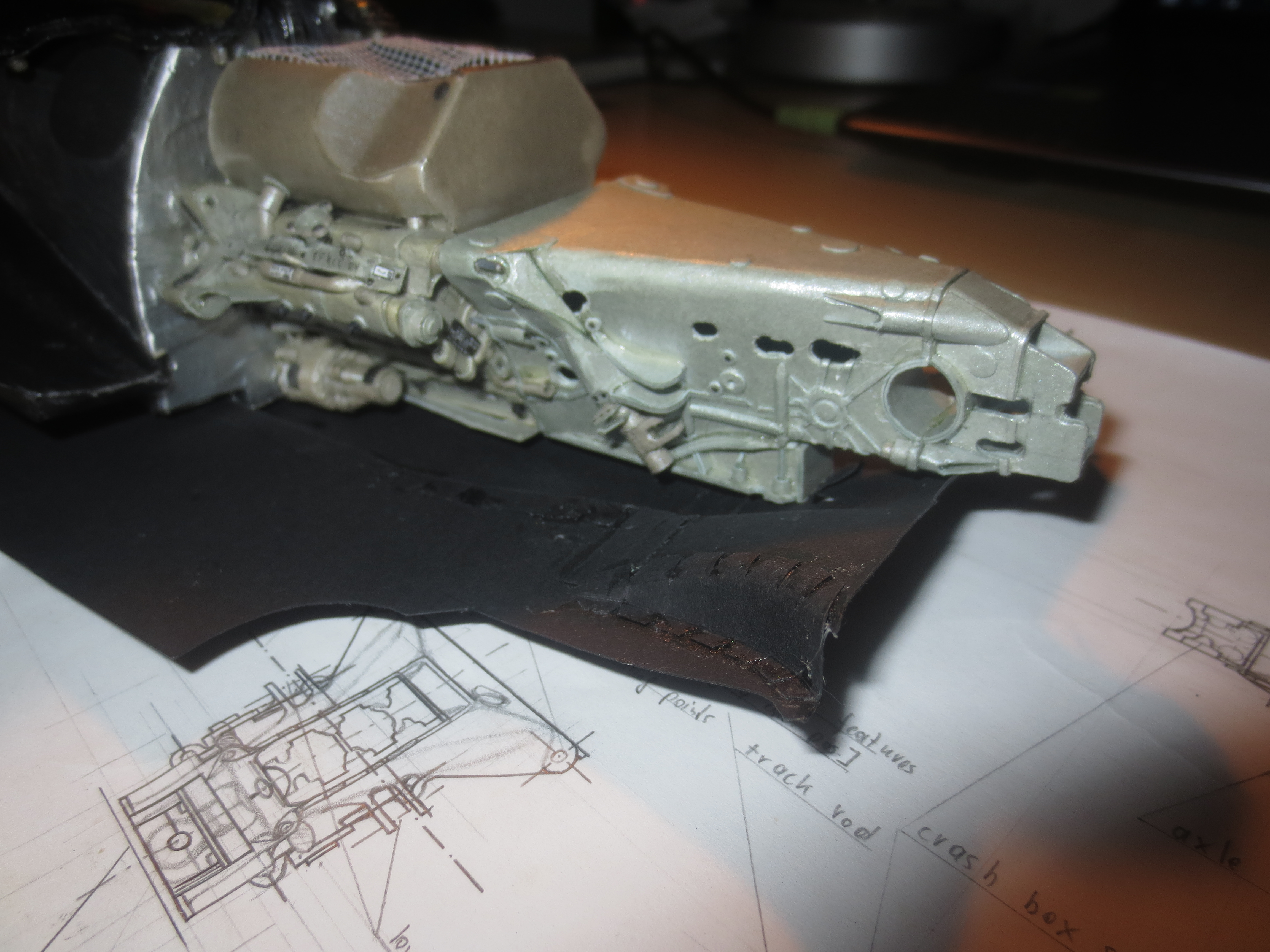
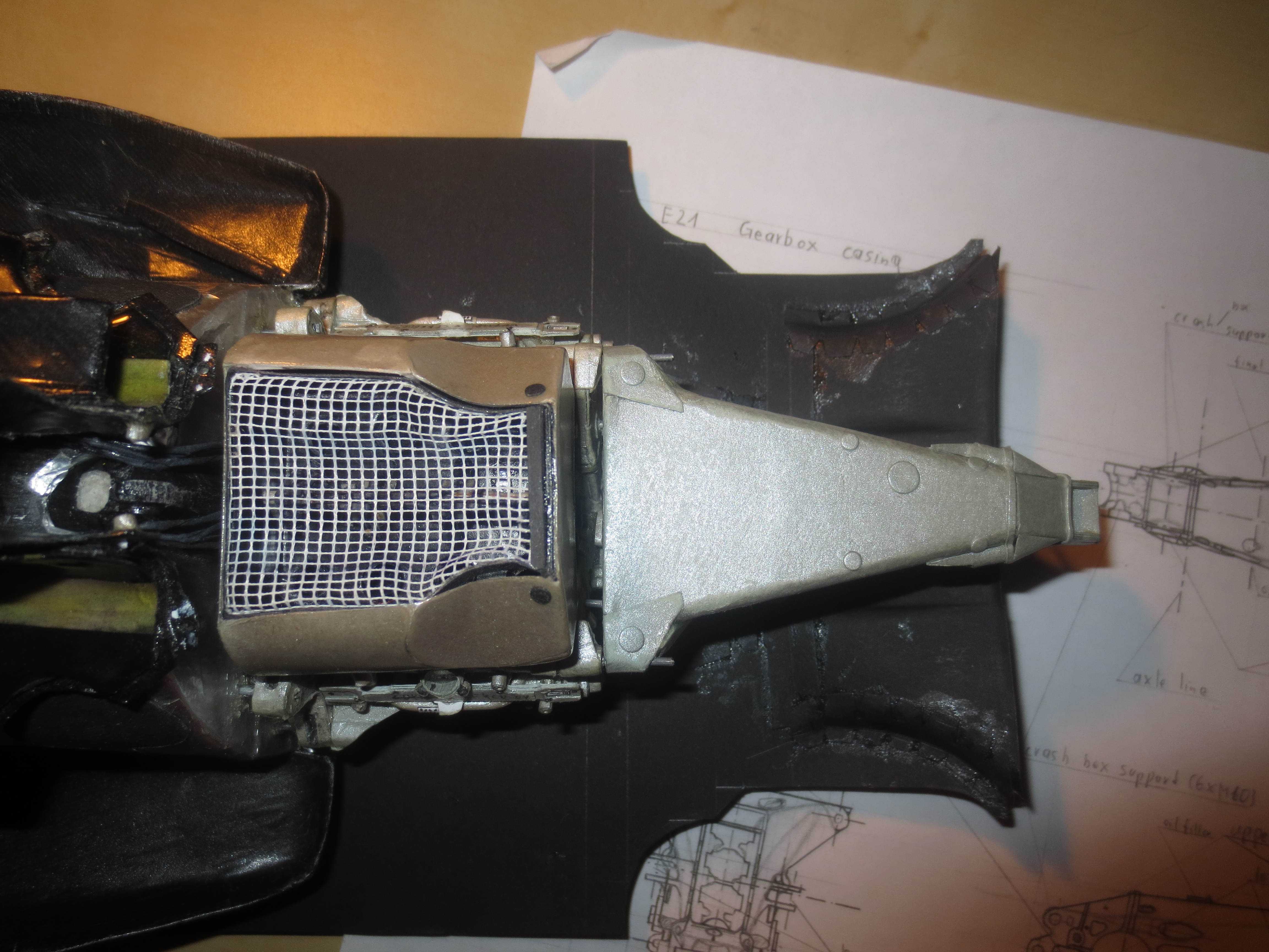
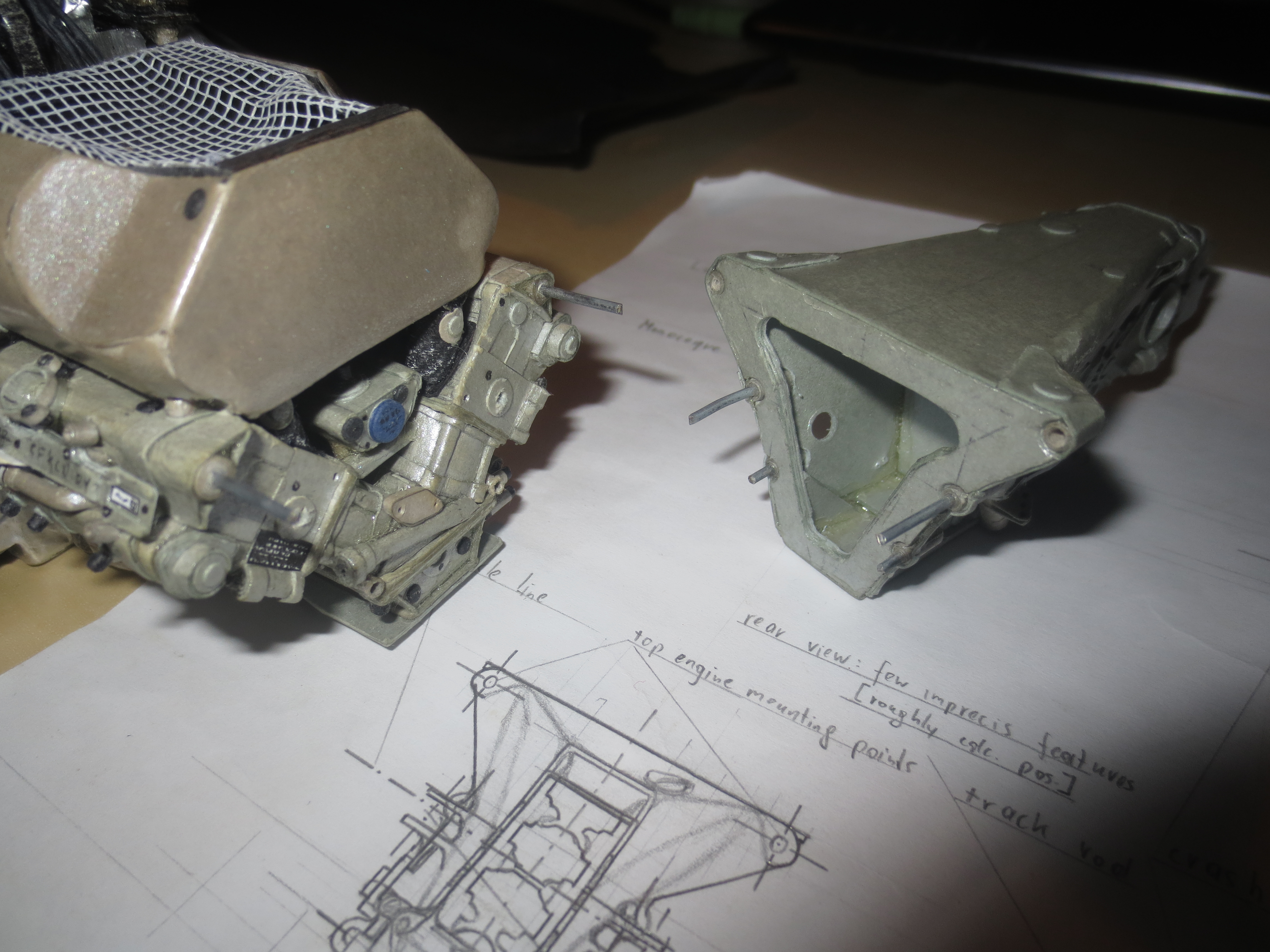
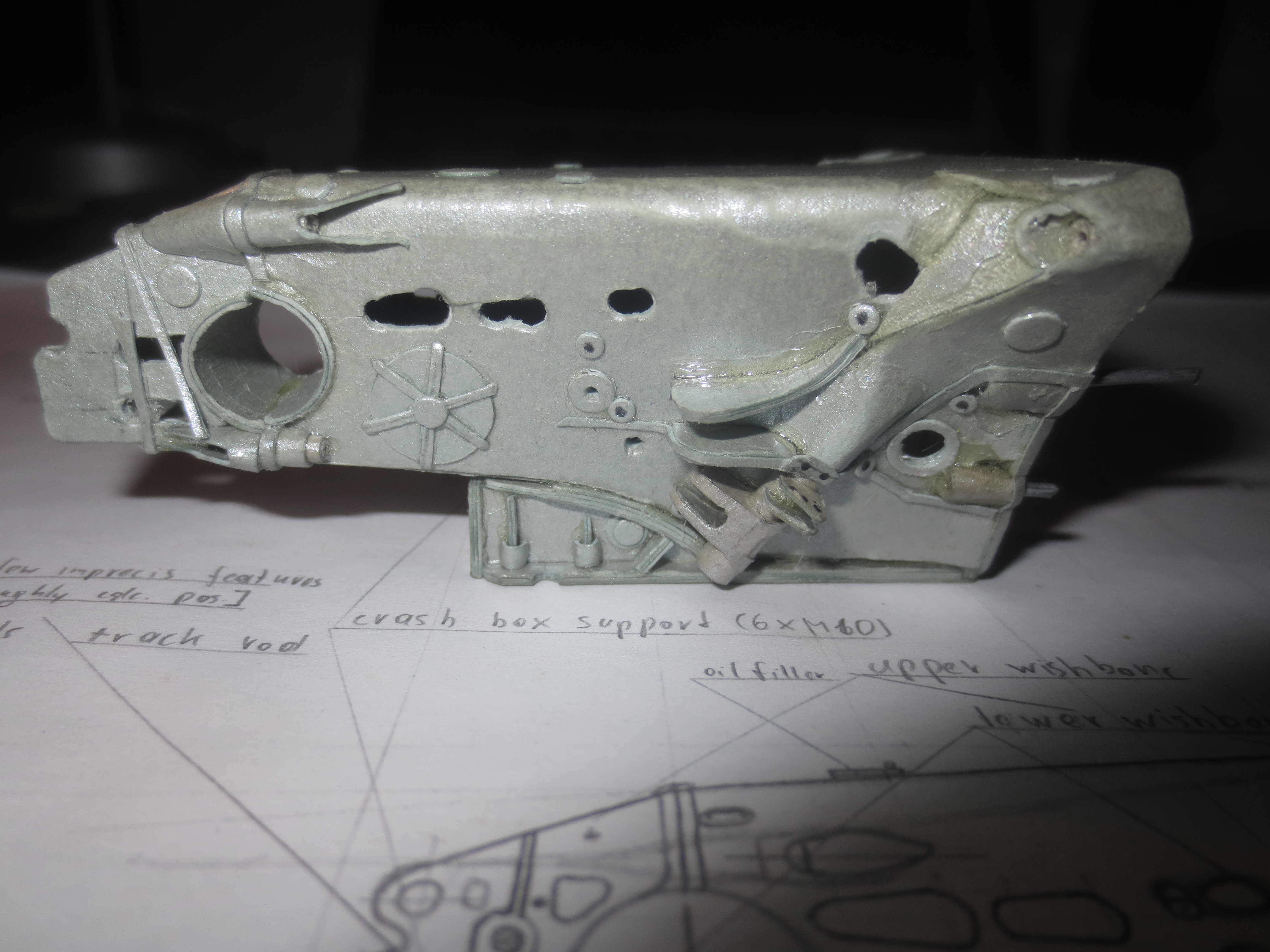
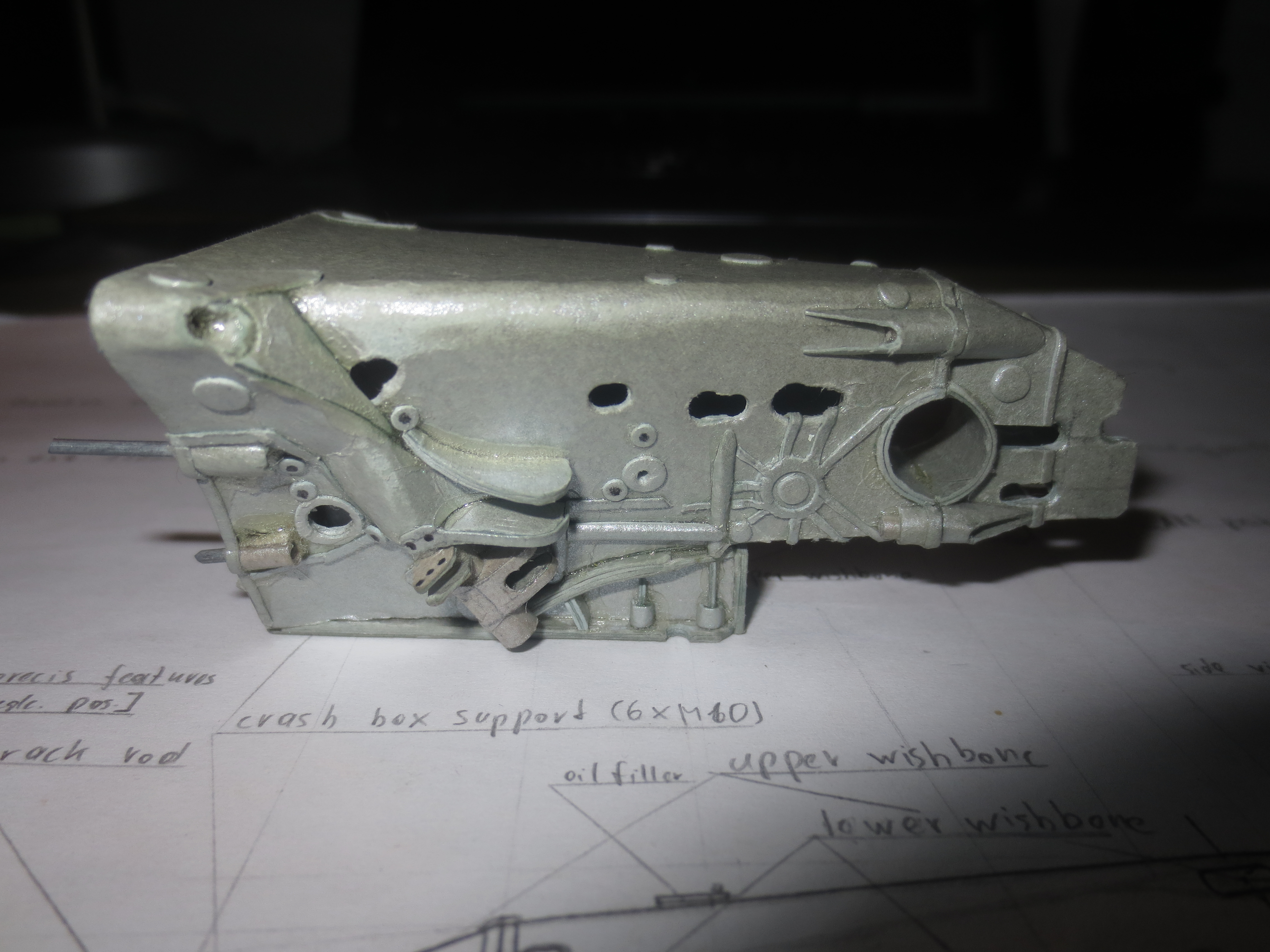
That was pretty much it. There are still 2 layers of lacquer missing, which will be done during engine manufacturing. Now I already revealed what's up next. Yeah, It's the Renault engine.
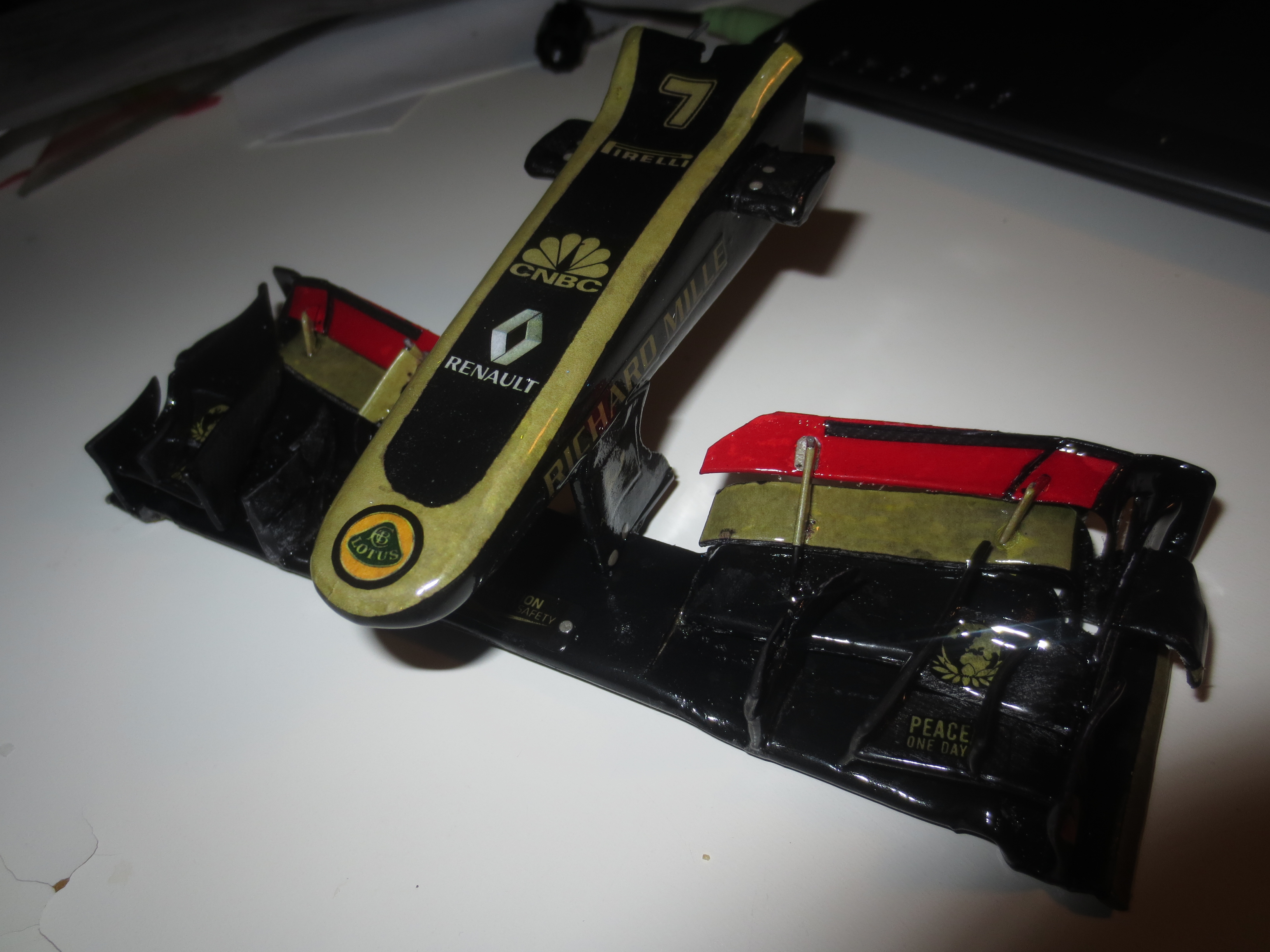
That's it for now, I hope it won't take that long to the next update.
Cheers,
Paul


