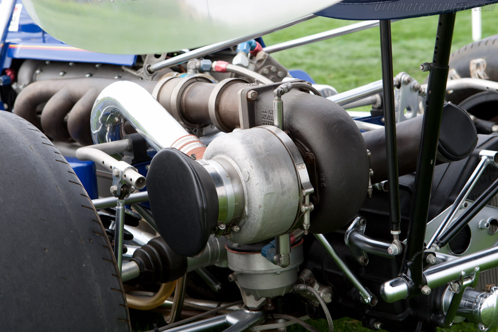
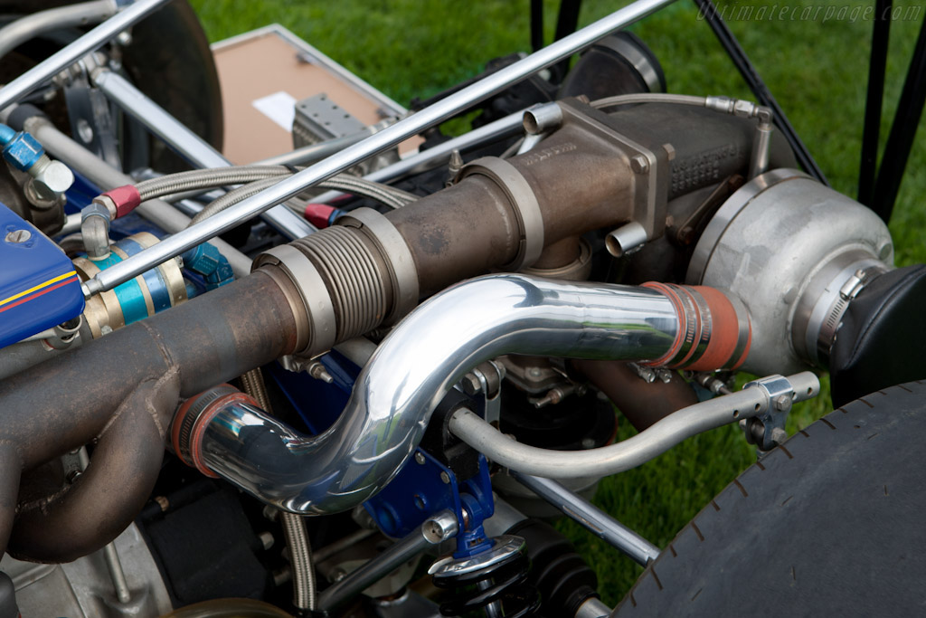
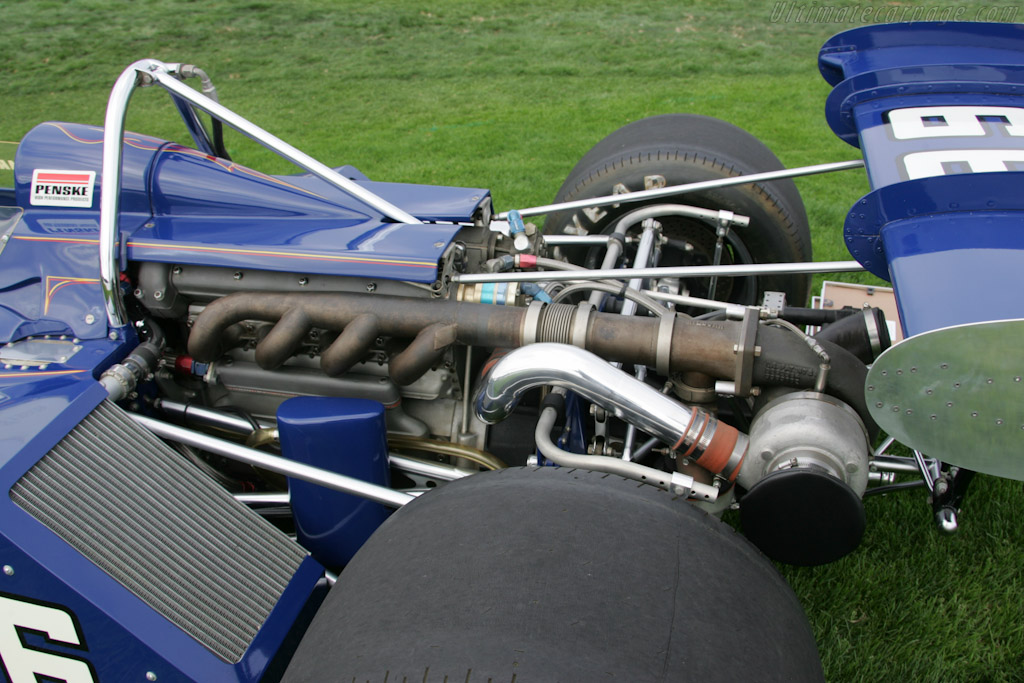
Here is a
![Image](http://www.turboneticsinc.com/pageimages/technical/compressor_map_01.jpg)
interesting, ..... but .....Foyle wrote: ..... The really key consideration is that you are trying to preserve as much blowdown gas velocity from when the exhaust valve cracks open as possible, as it is that initial pulse that has most of the energy and any efforts to slow it down or recover that energy as pressure will end up wasting much of it with diffusion losses.
Company I worked for developed a high performance 3 cylinder turbocharged engine (1.2L 240hp). We found very slight advantage for separate runners over log. But we needed to run over much larger range of conditions (car application). Given narrow rpm range of 10400-12000 it is quite possible that a log manifold can be made near-optimal. ,,,,
They are very different things. Lag is a throttle response delay which can occur at any rpm above the boost threshold eg engine is operating at max torque rpm but throttle is trailing eg during cornering and boost = zero. Driver nails throttle at corner exit, boost = very small number because turbo speed is low and torque is much lower than it should be at this rpm. Some time later the turbo has accelerated, full boost is available as is full torque. Time delay between driver nailing throttle and full boost arrival = turbo lag.jz11 wrote:in my mind the threshold and lag are essentially the same thing (and something that competition turbocharged engine doesn't care about, since it it not there, or doesn't matter),
At first I thought axial flow turbines were not permitted by the regulations, but they just limit the turbine to a single stage.Holm86 wrote:Have we ever seen the Mercedes exhaust turbine properly?? I wonder if they've created an axial flow turbine instead of centrifugal. Would exhaust pulses be less important in an axial flow turbine??
Turbomachinery Design and Theory wrote:The choice of turbine depends on the application, though it is not
always clear that any one type is superior. For small mass flows, the radial
machine can be made more efficient than the axial one. The radial turbine is
capable of a high-pressure ratio per stage than the axial one. However, multistaging
is very much easier to arrange with the axial turbine, so that large overall
pressure ratios are not difficult to obtain with axial turbines.
The way I understand it, is that while tubular would be more beneficial and efficient on a traditional turbocharged engine where you need to nurse the exhaust pulses for throttle response, the Merc unit is anything but traditional. The Offenhauser layout that the Merc unit is mimicking gives a tremendous packaging advantage to the Mercedes W05. The key lies in the split turbo setup that Mercedes is running where the turbine is being spun up by the MGU-H to eliminate turbo lag. A tubular exhaust setup doesn't matter here since there is no benefit to be had. I'm sure someone with more knowledge can chime in on this.Manifold design on turbocharged applications is deceptively complex as there many factors to take into account and trade off General design tips for best overall performance are to:
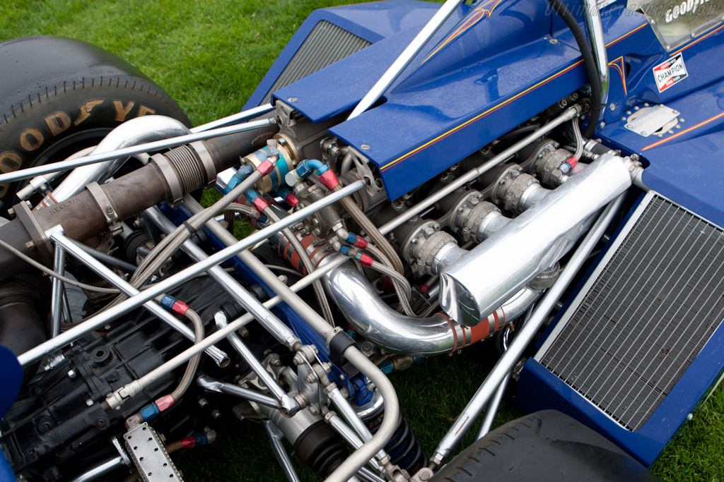
-Maximize the radius of the bends that make up the exhaust primaries to maintain pulse energy
-Make the exhaust primaries equal length to balance exhaust reversion across all cylinders
-Avoid rapid area changes to maintain pulse energy to the turbine
-At the collector, introduce flow from all runners at a narrow angle to minimize "turning" of the flow in the collector
-For better boost response, minimize the exhaust volume between the exhaust ports and the turbine inlet
-For best power, tuned primary lengths can be used
Cast manifolds are commonly found on OEM applications, whereas welded tubular manifolds are found almost exclusively on aftermarket and race applications. Both manifold types have their advantages and disadvantages. Cast manifolds are generally very durable and are usually dedicated to one application. They require special tooling for the casting and machining of specific features on the manifold. This tooling can be expensive.
On the other hand, welded tubular manifolds can be custom-made for a specific application without special tooling requirements. The manufacturer typically cuts pre-bent steel U-bends into the desired geometry and then welds all of the components together. Welded tubular manifolds are a very effective solution. One item of note is durability of this design. Because of the welded joints, thinner wall sections, and reduced stiffness, these types of manifolds are often susceptible to cracking due to thermal expansion/contraction and vibration. Properly constructed tubular manifolds can last a long time, however. In addition, tubular manifolds can offer a substantial performance advantage over a log-type manifold.
A design feature that can be common to both manifold types is a " DIVIDED MANIFOLD" , typically employed with " DIVIDED " or "twin-scroll" turbine housings. Divided exhaust manifolds can be incorporated into either a cast or welded tubular manifolds (see Figure 5. and Figure 6.).
The concept is to DIVIDE or separate the cylinders whose cycles interfere with one another to best utilize the engine's exhaust pulse energy.
For example, on a four-cylinder engine with firing order 1-3-4-2, cylinder #1 is ending its expansion stroke and opening its exhaust valve while cylinder #2 still has its exhaust valve open (cylinder #2 is in its overlap period). In an undivided exhaust manifold, this pressure pulse from cylinder #1's exhaust blowdown event is much more likely to contaminate cylinder #2 with high pressure exhaust gas. Not only does this hurt cylinder #2's ability to breathe properly, but this pulse energy would have been better utilized in the turbine.
The proper grouping for this engine is to keep complementary cylinders grouped together-- #1 and #4 are complementary; as are cylinders #2 and #3. Because of the better utilization of the exhaust pulse energy, the turbine's performance is improved and boost increases more quickly.
http://www.turbobygarrett.com/turbobyga ... _manifolds
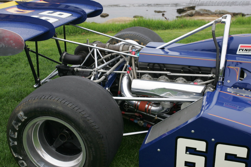
You must not be familiar with the Drake-Offenhauser.riff_raff wrote:No race engine would use a log-type exhaust manifold. Tuned headers are always far more effective, even with a turbocharger.
xpensive wrote:There you go gg, think turbine - clutch - MGUH - clutch - compressor. Ingenious and its all within the rules.
As you said, this is where their poweradvantage is coming from. De-clutching the compressor and sending all turbine power to the MGUH whenever it's not needed is your other alternative. Superswift electromagnetic clutches makes it possible.
So, the shaft assembly can be composed of many differnt bits, but at no time can any of those bits rotate at a different speed.5.1.6 Pressure charging may only be effected by the use of a sole single stage compressor linked to a sole single stage exhaust turbine by a shaft assembly parallel to the engine crankshaft and within 25mm of the car centre line. The shaft must be designed so as to ensure that the shaft assembly, the compressor and the turbine always rotate about a common axis and at the same angular velocity, an electrical motor generator (MGU-H) may be directly coupled to it.
A dual clutch system wouldn't give any benefit.5.2.4 The MGU-H must be solely mechanically linked to the exhaust turbine of a pressure charging system. This mechanical link must be of fixed speed ratio to the exhaust turbine and may be clutched.
Overruns what?xpensive wrote:an electrical motor generator (MGU-H) may be directly coupled to it.
Which overruns it all, when it "may be".