Rear Wing Idea

Here are our CFD links and discussions about aerodynamics, suspension, driver safety and tyres. Please stick to F1 on this forum.
riff_raff
riff_raff
132
Joined: 24 Dec 2004, 10:18

Re: Rear Wing Idea

Post

trinidefender wrote: Still want to try to tell me that they are vortex GENERATING types? The winglets reduce the size and strength of a wingtip vortex that is present on a winglet-less wing design. In actuality fact you can say that they are vortex reducing devices.
I agree. Winglets are devices that produce an airflow at the end of the horizontal span that results in better lift/drag performance from the wing. And the airfoil profile of the vertical tip of the winglet is designed to produce minimal wake vortex flow. But since the AoA of the tip airfoil is fixed it still can generate tip vortex wake flows under conditions of yaw or pitch.

Regardless, given the size (6-8 ft) and weight ( a couple hundred pounds each) of the winglets used on some commercial aircraft like the 737, they must be very effective at improving main wing lift versus the amount of drag they add.
"Q: How do you make a small fortune in racing?
A: Start with a large one!"

trinidefender
trinidefender
317
Joined: 19 Apr 2013, 20:37

Re: Rear Wing Idea

Post

riff_raff wrote:
trinidefender wrote: Still want to try to tell me that they are vortex GENERATING types? The winglets reduce the size and strength of a wingtip vortex that is present on a winglet-less wing design. In actuality fact you can say that they are vortex reducing devices.
I agree. Winglets are devices that produce an airflow at the end of the horizontal span that results in better lift/drag performance from the wing. And the airfoil profile of the vertical tip of the winglet is designed to produce minimal wake vortex flow. But since the AoA of the tip airfoil is fixed it still can generate tip vortex wake flows under conditions of yaw or pitch.

Regardless, given the size (6-8 ft) and weight ( a couple hundred pounds each) of the winglets used on some commercial aircraft like the 737, they must be very effective at improving main wing lift versus the amount of drag they add.
Sigh. They don't "produce" any airflow. They, in the simplest terms, create a barrier between the high and low pressure sides of the wing and and reduce the pressure differential between the two sides of a wing and hence reduce the drag and vortex that is formed.

Well that is another reason they are placed in the vertical. You can pitch your nose up and down all day and the vertical winglet stays at it's '0' angle of attack. It is only when you introduce yaw into the airframe that their angle of attack changes. On a commercial airliner yaw is only really present when landing sometimes to keep the runway on centreline as all other times the aircraft flies 'in trim' which is actually quite crucial for turns.

riff_raff
riff_raff
132
Joined: 24 Dec 2004, 10:18

Re: Rear Wing Idea

Post

Any outer surface of an aircraft moving thru the air produces an airflow. The ambient air passing over the moving aircraft surfaces is forced to flow in a manner it would not if left undisturbed. This is the fundamental definition of airflow.

http://www.merriam-webster.com/dictionary/airflow
"Q: How do you make a small fortune in racing?
A: Start with a large one!"

trinidefender
trinidefender
317
Joined: 19 Apr 2013, 20:37

Re: Rear Wing Idea

Post

riff_raff wrote:Any outer surface of an aircraft moving thru the air produces an airflow. The ambient air passing over the moving aircraft surfaces is forced to flow in a manner it would not if left undisturbed. This is the fundamental definition of airflow.

http://www.merriam-webster.com/dictionary/airflow
Fair enough the text book definition of airflow is that so I stand corrected. But to particularly say it is an airflow producing device would make the use of the word airflow slightly redundant as then ANY object on the cars exterior would be an airflow producing device wouldn't it?

When you said airflow I was thinking in terms of how a fan creates an airflow. I stand corrected.

That is why I would personally word it as a device that has an airflow going around it instead of "an airflow producing device"

But either way, I just hope it is clear to readers how exactly it works.

User avatar
variante
138
Joined: 09 Apr 2012, 11:36
Location: Monza

Re: Rear Wing Idea

Post

trinidefender wrote:in your simulation there is no induced flow around the wingtip because there IS NO WINGTIP in your simulation.
Ths statement makes me wonder, despite all your haughty claims, whether you understand how induced drag works...
What i did in that simulation was SIMULATING induced drag, thus the typical deviation of airflow caused by a vortex. I don't need a vortex to simulate its consequences (unless i want to get a perfectly accurate output, which is not the case).
trinidefender wrote:I get a lot of my information from a variety of sources and mainly a few aerospace engineers I know personally. I asked 2 today and they both told me that what you were saying is totally false.
I've got the slight impression that you did not communicate to them the actual problem we're discussing. If you were able to do it, you would understand it too. Just wanna know: did you show them the airfoil i tested?
trinidefender wrote:Btw you still haven't been able to state where the energy to create the vortex comes from if it isn't manifested in the form of drag. Or are you just avoiding my question?
The vortex takes energy from "form drag"; it is a symptom of form drag and efficiency of the wing. There are two ways the vortex can create drag: 1=interacion between its low pressure core and the bodywork (but it's not the case we're discussing), 2=induced drag.
When induced drag is 0 and point n°1 is negligible, then the vortex is "harmless", drag wise.

BTW we've been discussing about a small, off topic detail. I haven't been able to convince you despite the CFD "experiment" i provided, and i don't have the "stamina" to keep on trying to convince you. All i can do now is recommend you to look again at what we've been discussing and to think out of the box.

User avatar
hollus
Moderator
Joined: 29 Mar 2009, 01:21
Location: Copenhagen, Denmark

Re: Rear Wing Idea

Post

Variante, the vortex has kinetic energy in its rotating flow. Where did this energy come from?
Rivals, not enemies.

Blanchimont
Blanchimont
214
Joined: 09 Nov 2012, 23:47

Re: Rear Wing Idea

Post

variante wrote:I simulated infinite wingspan. Induced drag flow was simulated changing angulation of the airflow (0°, 1°, 5°)
How can you simulate an infinite wingspan and induced drag at the wing tips at the same time?

I assume that your modelled wing has contact to two boundary surfaces in your CFD model? If so, no flow from the high pressure to the low pressure side can exist and no vortex can be present there.

A picture would of your model and a plot of the velocity distribution just behind the wing would be very useful, i think!
Dear FIA, if you read this, please pm me for a redesign of the Technical Regulations to avoid finger nose shapes for 2016! :-)

User avatar
variante
138
Joined: 09 Apr 2012, 11:36
Location: Monza

Re: Rear Wing Idea

Post

hollus wrote:Variante, the vortex has kinetic energy in its rotating flow. Where did this energy come from?
From air bleeding (=moving) from the high pressure field of the wing to the low pressure one, obviously. But that's not the point since it has nothing to do (direcly) with induced drag, the fulcrum of the dispute.
A more inherent question would be: how does the vortex release its energy?
Blanchimont wrote:How can you simulate an infinite wingspan and induced drag at the wing tips at the same time?
Isn't induced drag caused by a downwash of the airstream? Ok, the vortex is responsible for that downwash, but why can't i just simulate the downwash itself?
In short, i only considered the direct cause of induced drag, not simulating the whole chain of causes that you would find in a complete simulation. In a complete simulation it would be much harder to extrapolate induced drag from form drag, wouldn't it?
Blanchimont wrote:A picture would of your model and a plot of the velocity distribution just behind the wing would be very useful, i think!
A soon as possible.

trinidefender
trinidefender
317
Joined: 19 Apr 2013, 20:37

Re: Rear Wing Idea

Post

variante wrote:
hollus wrote:Variante, the vortex has kinetic energy in its rotating flow. Where did this energy come from?
From air bleeding (=moving) from the high pressure field of the wing to the low pressure one, obviously. But that's not the point since it has nothing to do (direcly) with induced drag, the fulcrum of the dispute.
A more inherent question would be: how does the vortex release its energy?
Blanchimont wrote:How can you simulate an infinite wingspan and induced drag at the wing tips at the same time?
Isn't induced drag caused by a downwash of the airstream? Ok, the vortex is responsible for that downwash, but why can't i just simulate the downwash itself?
In short, i only considered the direct cause of induced drag, not simulating the whole chain of causes that you would find in a complete simulation. In a complete simulation it would be much harder to extrapolate induced drag from form drag, wouldn't it?
Blanchimont wrote:A picture would of your model and a plot of the velocity distribution just behind the wing would be very useful, i think!
A soon as possible.
Induced drag and form drag are two different things buddy. Stop getting them mixed up.

- For an aircraft form drag rises with the square of the velocity I.e. It has a quadratic relationship.
- induced drag on the other hand tends to reduce to a certain point as velocity increases. That is because as velocity increases, lift upon a wing increases. To stay in level flight the lift has to be kep constant and not increase. Therefore to achieve this the AoA is reduced. As the AoA is reduced the induced drag is reduced.

Image

That's true gives a general idea of drag of an aircraft.

Yes I showed it to both of them and they say that by you simulating an infinite wing span it makes the results incorrect as it gets rid of induced drag. So again I say, try and do a simulation with a limited wingspan and zero induced drag while developing lift and I guarantee that you won't be able to.

The way you did it you are assuming to many things and skipping to many process in the CFD.

Nobody ever said induced drag is caused by the down wash of an airstream. What was said was that induced drag is the drag created in the production of lift, two very different things. It appears English language isn't you first language and you may have gotten confused by that statement but I can assure you that "induced drag is caused by the down wash of an airstream" is not the same as "induced drag is the drag created in the production of lift." The second statement simply means, when you produce lift, induced drag will be present in some form.

Lastly. Think about the tip of a wing. When the airflow rotates around the tip of the wing from the high pressure side to the low pressure side it actually reduces the local angle of attack but at the same time does not reduce the drag with it. Therefore it makes part of the wing (closest to the tip) much less effective in producing lift. What the vertical wingtip does is create a barrier between the high and low pressure sides and reduces this airflow from the high pressure side to the low pressure side. By reducing this airflow you are effectively restoring the local AoA of part of the wing and hence resulting in more of the wing effectively creating lift with no increase in drag.

*note* some people refer to all other types of drag as parasitic drag (such as what is shown in the diagram) except induced drag which is, again, drag created AS A RESULT OF the creation of lift. I myself prefer to use the term parasitic drag to just encompass parts of a body that don't have anything to do with lift production such as the body of an aircraft (which has its own form drag and skin friction numbers) while if I say form drag or skin friction individually I'll usually be talking about the wing itself.

trinidefender
trinidefender
317
Joined: 19 Apr 2013, 20:37

Re: Rear Wing Idea

Post

Blanchimont wrote:
variante wrote:I simulated infinite wingspan. Induced drag flow was simulated changing angulation of the airflow (0°, 1°, 5°)
How can you simulate an infinite wingspan and induced drag at the wing tips at the same time?

I assume that your modelled wing has contact to two boundary surfaces in your CFD model? If so, no flow from the high pressure to the low pressure side can exist and no vortex can be present there.

A picture would of your model and a plot of the velocity distribution just behind the wing would be very useful, i think!
Blanchimont that's exactly the problem that he isn't getting. You can not simulate induced drag at the wingtips if his simulation HAS NO WINGTIPS. Sometimes I wish I could explain things in a shorter way but I just end up blabbing and have to stop myself typing at some point and then get frustrated when I can't explain myself properly. Note to self, work on explaining things lol.

User avatar
variante
138
Joined: 09 Apr 2012, 11:36
Location: Monza

Re: Rear Wing Idea

Post

trinidefender, i'm sorry that you cannot understand the point. It must be a language problem, i hope... Meanwhile stop trying to teach me with arrogance how aerodynamics work and inform yourself on the actual functioning of induced drag.

----

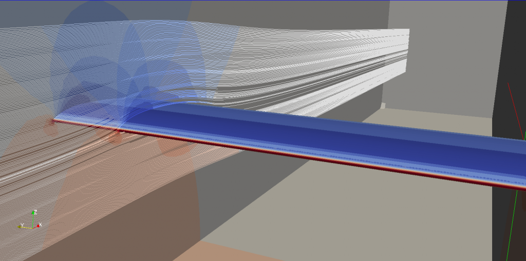
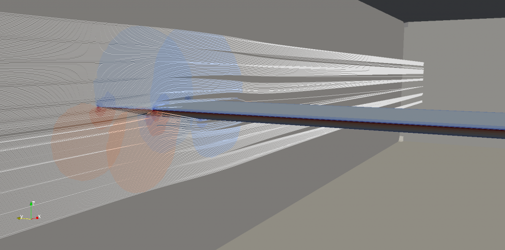
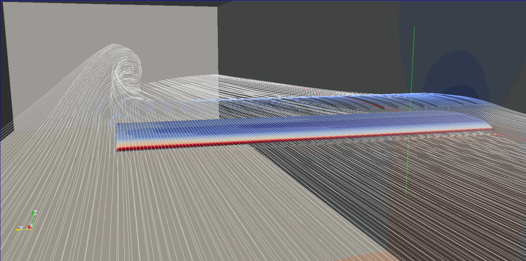
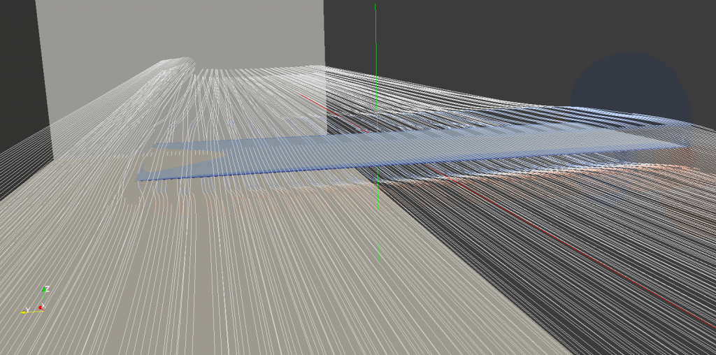
BTW i did run new simulations; hopefully they are more "complete" or easier to understand.

I tested 2 wing sections, a conventional airfoil and the airfoil that, i think, isn't affected by induced drag.
Two scenarios for each airfoil: realistic (with wingtip vortex) and ideal (with infinite wall at the wingtip, therefore no vortex).

Expected results?
-In the realistic scenario we should observe the greatest amount of drag, given by the sum of Form drag and Induced drag.
-In the ideal scenario we should observe only Form drag, since the absence of vortices doesn't allow the presence of induced drag.
However, if my opinion is the right one, my airfoil should not be negatively affected by downwash (unlike the conventional airfoil), therefore should have induced drag = 0 even in the realistic scenario. In other words my airfoil should present identical or inferior total drag in the realistic scenario than in the ideal scenario.

Ideal scenario, conventional airfoil:
total drag: 35N
Image

Ideal scenario, my airfoil:
total drag: 209N
Image

Realistic scenario, conventional airfoil:
total drag: 93N
Image

Realistic scenario, my airfoil:
total drag: 195N
Image

These results confirm my suppositions and my previous simulation.

In case someone knows how to make better simulations, let me know (politely, if possible...)

Blanchimont
Blanchimont
214
Joined: 09 Nov 2012, 23:47

Re: Rear Wing Idea

Post

Thanks for the pictures, variante.

But before i go on further, please give us more details on the results of your simulations.

What are the lift force numbers belonging to the different models?
Is the chord and the velocity the same for all models?
What does the colour represent, pressure or velocity or...?
Is the scale of the plot the same for all the models so that the colours can be compared?
What is the maximum and minimum pressure for each simulated model?
Dear FIA, if you read this, please pm me for a redesign of the Technical Regulations to avoid finger nose shapes for 2016! :-)

trinidefender
trinidefender
317
Joined: 19 Apr 2013, 20:37

Re: Rear Wing Idea

Post

variante wrote:trinidefender, i'm sorry that you cannot understand the point. It must be a language problem, i hope... Meanwhile stop trying to teach me with arrogance how aerodynamics work and inform yourself on the actual functioning of induced drag.

----

BTW i did run new simulations; hopefully they are more "complete" or easier to understand.

I tested 2 wing sections, a conventional airfoil and the airfoil that, i think, isn't affected by induced drag.
Two scenarios for each airfoil: realistic (with wingtip vortex) and ideal (with infinite wall at the wingtip, therefore no vortex).

Expected results?
-In the realistic scenario we should observe the greatest amount of drag, given by the sum of Form drag and Induced drag.
-In the ideal scenario we should observe only Form drag, since the absence of vortices doesn't allow the presence of induced drag.
However, if my opinion is the right one, my airfoil should not be negatively affected by downwash (unlike the conventional airfoil), therefore should have induced drag = 0 even in the realistic scenario. In other words my airfoil should present identical or inferior total drag in the realistic scenario than in the ideal scenario.

Ideal scenario, conventional airfoil:
total drag: 35N
http://i1372.photobucket.com/albums/ag3 ... 406873.png

Ideal scenario, my airfoil:
total drag: 209N
http://i1372.photobucket.com/albums/ag3 ... 9d726b.png

Realistic scenario, conventional airfoil:
total drag: 93N
http://i1372.photobucket.com/albums/ag3 ... c15ec1.png

Realistic scenario, my airfoil:
total drag: 195N
http://i1372.photobucket.com/albums/ag3 ... 2c654b.png

These results confirm my suppositions and my previous simulation.

In case someone knows how to make better simulations, let me know (politely, if possible...)
Not all of induced drag comes from the wing tips. Only a portion of it. Induced drag is also the drag created by turning the airflow downwards. That is why it is known as drag created in the production of lift.

However since wingtip vortices are part of induced drag, by reducing the wingtip vortices through the use of vertical wingtips you reduce that part contributing to induced drag.

To tie it together, the total induced drag consists of drag created by turning the airflow downwards + vortex wingtip drag + any other drag created in the production of lift. The vertical winglet only helps to deal with the problem of vortex wingtip drag.

May I ask why you didn't post any lift numbers from the CFD simulations?

You keep claiming that induced drag is only from the wingtips while I am trying to say, and backing it up with sources, that induced drag is wingtip vortex drag AND all other drag created in the production of lift.

If you don't believe me then here: http://www.oxforddictionaries.com/defin ... duced-drag
"Induced drag; That part of the drag on an aerofoil which arises from the development of lift."

User avatar
variante
138
Joined: 09 Apr 2012, 11:36
Location: Monza

Re: Rear Wing Idea

Post

Blanchimont wrote:What are the lift force numbers belonging to the different models?
Ideal scenario:
1st: Drag = 35N, Lift = 3010N
2nd: Drag = 209N, Lift = 608N
Realistic scenario:
1st: Drag = 93N, Lift = 2154N
2nd: Drag = 195N, Lift = 381N
Blanchimont wrote:Is the chord and the velocity the same for all models?
Yes, same chord, same velocity, same wingspan,...
Blanchimont wrote:What does the colour represent, pressure or velocity or...?
Pressure.
Blanchimont wrote:Is the scale of the plot the same for all the models so that the colours can be compared?
Yes.
Blanchimont wrote:What is the maximum and minimum pressure for each simulated model?
There aren't anomalous peaks nor particular discrepancies between the scenarios, if that's what you want to know.
trinidefender wrote:"Induced drag; That part of the drag on an aerofoil which arises from the development of lift."
Then where does Form drag start from? Can you put a boundary between the two kinds of drag? Or are you suggesting that they may be the same thing?
If that definition is correct, then a wing with infinite span will still have induced drag. Is that what you're saying? (i'm asking seriously, without malice)

trinidefender
trinidefender
317
Joined: 19 Apr 2013, 20:37

Re: Rear Wing Idea

Post

variante wrote:
Blanchimont wrote:What are the lift force numbers belonging to the different models?
Ideal scenario:
1st: Drag = 35N, Lift = 3010N
2nd: Drag = 209N, Lift = 608N
Realistic scenario:
1st: Drag = 93N, Lift = 2154N
2nd: Drag = 195N, Lift = 381N
Blanchimont wrote:Is the chord and the velocity the same for all models?
Yes, same chord, same velocity, same wingspan,...
Blanchimont wrote:What does the colour represent, pressure or velocity or...?
Pressure.
Blanchimont wrote:Is the scale of the plot the same for all the models so that the colours can be compared?
Yes.
Blanchimont wrote:What is the maximum and minimum pressure for each simulated model?
There aren't anomalous peaks nor particular discrepancies between the scenarios, if that's what you want to know.
trinidefender wrote:"Induced drag; That part of the drag on an aerofoil which arises from the development of lift."
Then where does Form drag start from? Can you put a boundary between the two kinds of drag? Or are you suggesting that they may be the same thing?
If that definition is correct, then a wing with infinite span will still have induced drag. Is that what you're saying? (i'm asking seriously, without malice)
That is exactly what I am saying. A wing with infinite wingspan will still have some induced drag. However it will no have any induced drag as a result of wing tip vortices. Therefore reducing wingtip vortex drag through the use of a vertical winglet provides an overall reduction in induced drag. Understand what I am saying now?

Now onto form drag. Form drag is considered a subset of profile drag which in itself is a subset of parasitic drag.

Form drag is physically the drag created by an object pushing its way through the air. When you add to that drag created by skin friction then the two together become profile drag. Form drag in itself rises with the square of the velocity.

Induced drag on the other hand is drag created by that object turning airflow downwards and creating a pressure difference between the two sides of an airfoil as a wing does and producing net lift.

I never had any malice intended.