Nose cone idea

Here are our CFD links and discussions about aerodynamics, suspension, driver safety and tyres. Please stick to F1 on this forum.
manchild
manchild
12
Joined: 03 Jun 2005, 10:54

Post

MMUK wrote:I reckon going with the inverted aperture would be better, feeding more air under the car. Also, in the current setup the air could have a difficult time negotiating the current aperture angle, you'd have to have a favourable pressure gradient for it to want to go up the aperture.

Ill mesh and run any CFD models you have if required. Flow vis pics as well as numerical data will follow. It would have to include a simple front wing though, to gain a better understanding of the required onset angle onto the aperture.
As I've already mentioned I made such drawings years ago and sent them to scarbs since I knew no other referent f1technical site/person. He kindly replied me after some initial observation that it would disturb feeding of airbox. Perhaps scarbs still has those drawings, I've lost them. If he has them I hope he can post them here.

It would be great if you could run some CFD on it. Can't wait to see and hear the results. Thanks in advance.

RACKITUP
RACKITUP
0
Joined: 23 Apr 2006, 18:27

Post

Image

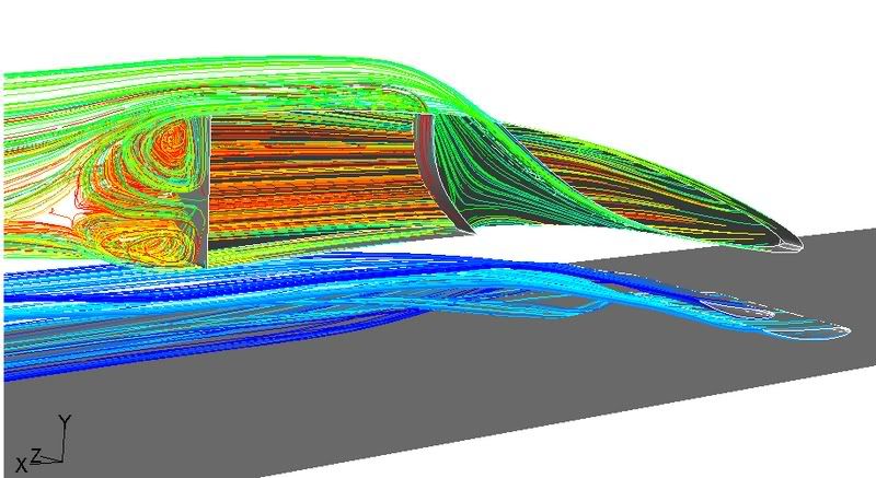
I will be back to work tomorrow, so I am unsure if I will be able to get any decent results. Unfortunately I don't have the time nor personal resources to do a complete car, but hey I've given it ago ;)

Objectives
Personally, I was looking for two things:
1. An increase in circulation for the front wing assembly
2. Formation of vortices and their likely propagation downstream

Methodology
The grid is unstructured and very coarse; due to be refined in areas of high vorticity and static/total pressure gradients. I left the trailing edge (TE) of the nose as a bluff body as I wanted to fix the point of seperation.

Initial impressions.
1. I converged the area under the nose, to constrict the flow and speed it up further; this seemed to have negliable effect, and would be very draggy
2. Seperation and recirculation at the top edge, due to the latter face being too vertical

Overall thoughts.
Pretty pointless unless you simulate the rest of the car. Very rarely are parts put on the car purely for local downforce.

1. I am thinking it would be very sensitive to yaw
2. Take flow from the undertray

However, definately worth a go in a windtunnel...

Recommendations
1. If anyone else wants to jump on the CFD bandwagon, don't make the latter face vertical, definately make a smooth transition to the top surface of the nose downstream
2. Do it in straightline and yaw

manchild
manchild
12
Joined: 03 Jun 2005, 10:54

Post

RACKITUP wrote:Recommendations
1. If anyone else wants to jump on the CFD bandwagon, don't make the latter face vertical, definately make a smooth transition to the top surface of the nose downstream
2. Do it in straightline and yaw
Yeah, yeah... no snowplows please :)

The sketches I made are based on shape of R26 nose cone. I reckon more neutral nose would be better (lower angle) as it would mean less drag since the attack angle of "wing" at the tip of the nose would be lower.

Regarding undertray issue... if this "wing" in the nose would create some downforce that would mean that front wing could be set at lower angle which would reduce drag and turbulence it creates influencing flow of air below sidepods too. Right?

User avatar
MMUK
0
Joined: 08 Apr 2007, 05:35

Post

You could do a study of both the current and inverted aperture case, and measure the flowrate to the airbox for each case as well as the quality of airflow.

I would of thought the current case would mess with the airflow to the airbox more as the downstream flow will be alot more 'lossy' (low in total pressure) having just worked its butt off through the nose cone. This lossy flow could play havoc downstream with the rest of the car such as the rear wing.

But who knows till a test is done! :lol:

Belatti
Belatti
33
Joined: 10 Jul 2007, 21:48
Location: Argentina

Post

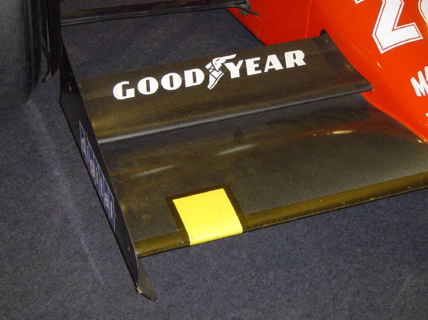
In the 80´s F1 cars had 2 front wings, one at each side of the nosecone
Image

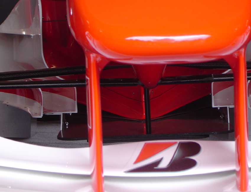
In early 90´s the nosecone was moved up (maybe sacrifiying some little front downforce), to make a sigle larger front wing (gaining there other downforce) and helping some airflow to go down the car and to the sidepods better
Image

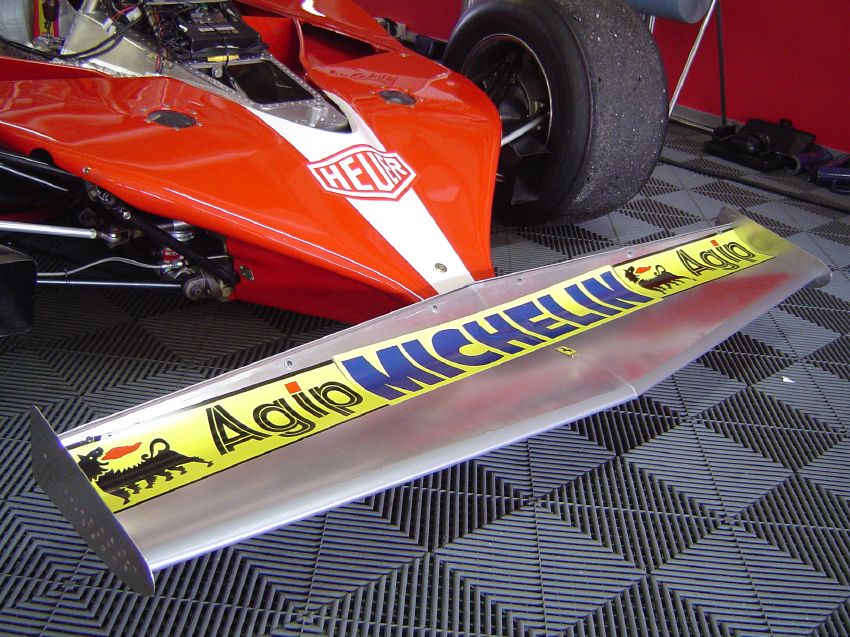
Now, I´m guessing because I know very little about aero development, but, IF WE GO BACK TO THE PRIMITIVE??? (obviously in a modern design way...???)
Image

in a modern design way means: not using that rough, turbulence provoking 312 front wing... the idea is simple: front wing in front of nosecone

JUST MY VAGUE IDEA! hope it contributes to open someones mind :D
"You need great passion, because everything you do with great pleasure, you do well." -Juan Manuel Fangio

"I have no idols. I admire work, dedication and competence." -Ayrton Senna

Belatti
Belatti
33
Joined: 10 Jul 2007, 21:48
Location: Argentina

Post

This old footwork nosecone barely represents what I was trying to picture in your engineer minds...

[img:1]http://l.yimg.com/www.flickr.com/images/spaceball.gif[/img]
"You need great passion, because everything you do with great pleasure, you do well." -Juan Manuel Fangio

"I have no idols. I admire work, dedication and competence." -Ayrton Senna

manchild
manchild
12
Joined: 03 Jun 2005, 10:54

Post

Everyone is silent. I guess it works and all teams are already testing it in wind tunnels 24/7 :lol:

Perhaps that's what Williams showed to Nico to make him stay for 2008 :lol:

mx_tifoso
mx_tifoso
0
Joined: 30 Nov 2006, 05:01
Location: North America

Post

This TopSecret JDM Z33 has a similar earo package from what I have read. Air flow from the underbody is vented through the CF ducts coming out of the bonnet to produce downforce at high speed. From what I understand it is a similar concept to the original "nose cone idea". Is it or is it not? You tell me.
Image
:arrow: http://www.topsecretjpn.com/home.shtml
:arrow: http://www.topsecretjpn.com/gallery.shtml
Forum guide: read before posting

"You do it, then it's done." - Kimi Räikkönen

Por las buenas soy amigo, por las malas soy campeón.

manchild
manchild
12
Joined: 03 Jun 2005, 10:54

Post

Those are just hot air outlets. The inlet contains radiator so there's no similarity at all. :wink:

mx_tifoso
mx_tifoso
0
Joined: 30 Nov 2006, 05:01
Location: North America

Post

manchild wrote:Those are just hot air outlets. The inlet contains radiator so there's no similarity at all. :wink:
Well that specific car is a few years old now, so since I first read the many articles over it, much time has passed and I can't recall the specific info over the aero. But I do remember reading how those ducts not only served for directing "hot air" from the engine bay (possibly), but directed underbody airflow out from the bonnet. I also remember seeing close-up pictures of the engine bay and the actual ducts, which came from a very low section of the engine bay, which led me even more to believe its similarity to the "nose cone idea".

I believe the structure is similar to this; the entry to the ducts is near the bottom of the engine bay (frontal area), the ducts are positioned to travel through the engine bay, and then connect with the bonnet to expel the underbody air out.

Maybe I misunderstood or I am completely wrong. If so, I apologize for the "misleading" info.
Forum guide: read before posting

"You do it, then it's done." - Kimi Räikkönen

Por las buenas soy amigo, por las malas soy campeón.

manchild
manchild
12
Joined: 03 Jun 2005, 10:54

Post

No need to apologize at all. :wink: My nose cone idea considers that frontal area is shaped as an inverted DF generating wing. So, the hole in the nose is not initial element, no, it is there only to enable functioning of frontal wing area.

Carbon
Carbon
4
Joined: 19 Jan 2004, 19:02
Location: Vancouver, BC

Post

Just going back to what mx_tofosi posted about the underside aero venting upwards and producing DF. I might be wrong, but I think there are a number of current closed-body sportscars that have this arrangement.

I'm also reasonably certain that the old Toyota GT1 (can't remember the name) that ran a few years ago had a very similar set up. I'll look for pics and post.

manchild
manchild
12
Joined: 03 Jun 2005, 10:54

Post

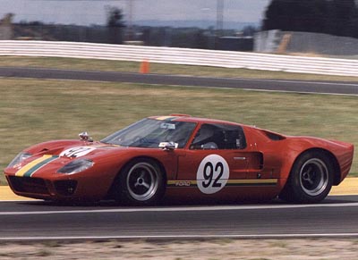
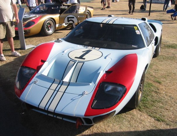
1966 :wink:

Image
Image

mx_tifoso
mx_tifoso
0
Joined: 30 Nov 2006, 05:01
Location: North America

Post

Carbon wrote:I might be wrong, but I think there are a number of current closed-body sportscars that have this arrangement.
I believe the Enzo has a similar arrangement. As Ferrari engineers didn't want to place wings on the surface of the body, so they went the route of adding "aerodynamics accesories" under the body. Incoming air directed out through the bonnet producing DF.
Or I could be wrong on this one, as I don't know where the radiator(s) are located at :? . Where do most rear-engine road cars have the radiator(s) :?:
Image :arrow: http://www.seriouswheels.com/cars/top-Ferrari-Enzo.htm

I aknowledge that what I have started isn't the same application as that of an F1 car, but as far as I know it is a similar concept applicable on road cars. And I appreciate you guys understanding my posts and helping me learn and comprehend these "aero topics", which I don't specialize in.
Forum guide: read before posting

"You do it, then it's done." - Kimi Räikkönen

Por las buenas soy amigo, por las malas soy campeón.

scarbs
scarbs
393
Joined: 08 Oct 2003, 09:47
Location: Hertfordshire, UK

Post

Yamahas, early nineties f1 inspired road car (a failed project called the OX11 IIRC) had such a shape. the space between the wheelarches was used to briedge a wing element.

I think Manchilds idea has some merit, Its been on my drawing board too, for many years. I think Williams walrus nose went some way towards this goal, but without the extra nose cone piece. I think the DF or drag gain will be from the wing itself and not the nosecone, despite its aerofoil shape. But the slots effect woudl be to send the front wings upwash over the top of the car, soemthing every designer is addign flaps and fins to avoid. So how much this would help bearing in mind the space and structural problems and no one adopting the solution suggests that may be the gains arent big enough.?