One point to note is that these tests were all conducted from an aeronautical point of view, where the aim was lift, so the aerofoil profile is "upside down" compared to what we need. Just draw it the other way up.
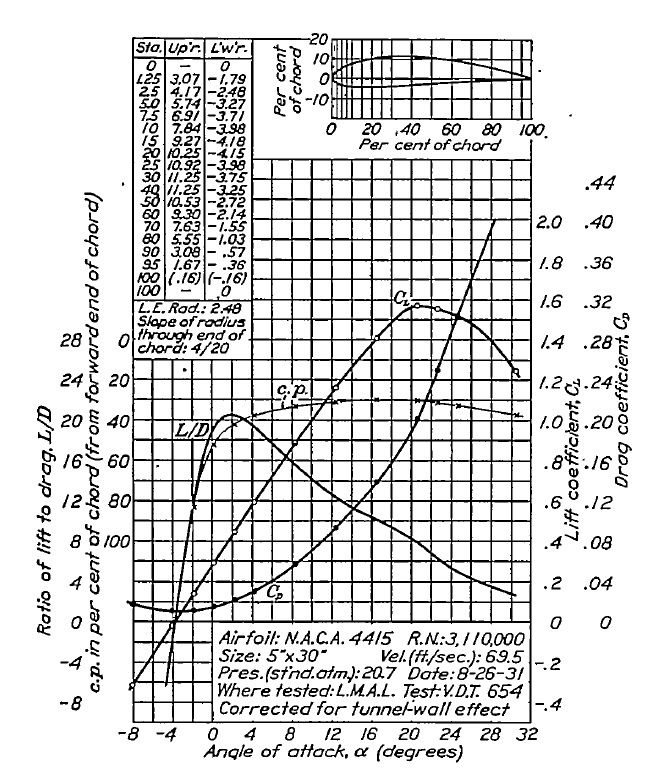
The full report can be found here:- http://naca.central.cranfield.ac.uk/rep ... rt-460.pdf
So, what does it tell you: well you have lines showing CL , CD and L/D based on the angle of Attack of the profile compared to the on-coming air direction.
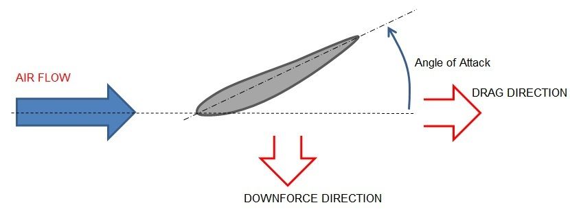
First of all you need to determine from your model your wing's angle of attack (A.o.A), which is measured as per below:
Then simply read up the chart from your angle of attack until you hit the CL, CD or L/D lines and then read across to the corresponding axis to find out the value for each.
So at 4 degrees A.o.A the CL reads off as approx 0.6, CD as approx 0.03 and L/D as approx 20:1
To determine the downforce or drag you must first multiple the CL or CD by the plan area of the wing to obtain CL.A or CD.A.
Then, as posted by AratzH above, to find the actual downfoce or Drag in Newtons you calculate as follows:-
downforce = CL.A x rho(air density) x V^2(velocity squared)
Drag = CD.A x rho(air density) x V^2(velocity squared)
where air density is in kg/m^3 and velocity is in m/s
I normally take air density as 1.22kg/m^3, and 100mph = 44.7m/s as per CAEDevice's post.
So now you can look for other wing profiles and make a selection and determine the your own downforce or drag figures, although, as posted above: the NACA data is for a slender wing without the wing tip vortex effect... so your performance is likely to be slightly worse than predicted...

