[KVRC ~ish] CCE LMP01

Post here information about your own engineering projects, including but not limited to building your own car or designing a virtual car through CAD.
User avatar
variante
138
Joined: 09 Apr 2012, 11:36
Location: Monza

Re: [KVRC ~ish] CCE LMP01

Post

@RickME85
on top of other people's tips, i would advise against the use of a "jordan floor transition" (or whatever that's called...) as the mesh size we're forced to use would greatly eclipse the small (and "delicate") geometries of that solution.

Also, you said to have observed and used my diffuser design, but i'm not recognizing much of it on your car... I'd advise you to watch it more carefully. Don't forget that any difference in design could lead to major and unexpected changes in results.

About diffuser design: you should focus 99% of your car's development on that. Try less aggressive geometries, for example; or -as i've already said- copy more carefully what others have done.

While designing your diffuser, n°1 priority is to avoid stall. Once that is assured, look for the greatest possible expansion ratios and don't forget to take advantage of ground effect.

User avatar
CAEdevice
49
Joined: 09 Jan 2014, 15:33
Location: Erba, Italy

Re: [KVRC ~ish] CCE LMP01

Post

variante wrote:@RickME85
on top of other people's tips, i would advise against the use of a "jordan floor transition" (or whatever that's called...) as the mesh size we're forced to use would greatly eclipse the small (and "delicate") geometries of that solution.
I agree, "micro" aerodynamics tricks are almost impossible: the mesh would be much more fine.
variante wrote: copy more carefully what others have done.
Consider the hole in the middle of the front wing: it is a way to direct air under the floor, but it is very difficult obtain that result without some lift under the nose. You should work on a better splitter (I choose another solution, but it would not be easy to transfer to your car without re-design almost al the fornt axle region).

User avatar
machin
162
Joined: 25 Nov 2008, 14:45

Re: [KVRC ~ish] CCE LMP01

Post

variante wrote:Also, you said to have observed and used my diffuser design, but i'm not recognizing much of it on your car... I'd advise you to watch it more carefully. Don't forget that any difference in design could lead to major and unexpected changes in results.
I think that comment from Ric was in respect to an iteration of the car that we haven't seen yet... I suspect that even if it is copied exactly (which, of course, it won't be), it'll work differently because the upstream, downstream and peripheral flow will be different, and it'll be a case of playing around with the design to see what works...

...will be interesting to see what performance the first iteration achieves...
COMPETITION CAR ENGINEERING -Home of VIRTUAL STOPWATCH

User avatar
RicME85
52
Joined: 09 Feb 2012, 13:11
Location: Derby

Re: [KVRC ~ish] CCE LMP01

Post

Have had issues with the next run, OCCFD has been giving divergeance when MAtt ran the stl files on his rig and AWS dumped it eventually too. I have worked on another version of the model and so far things seem to be working.

As for the Variante diffuser, I dont think I ever submitted a car with it on

User avatar
RicME85
52
Joined: 09 Feb 2012, 13:11
Location: Derby

Re: [KVRC ~ish] CCE LMP01

Post

Ok, finally got there.
Original plan was to include the Variante diffuser in this run but for some reason OCCFD didnt like the car with the new diffuser geometry.

I have changed the shrouding on the front suspension and the front crash structure as well as raising the lower elements of the front wing by 10mm and have changed the AOA on the upper element.

Image

Image

Image

User avatar
RicME85
52
Joined: 09 Feb 2012, 13:11
Location: Derby

Re: [KVRC ~ish] CCE LMP01

Post

Image

Image

Image

That last image looks to me like the front suspension cover is sending air quite high and effecting the rear wing


User avatar
machin
162
Joined: 25 Nov 2008, 14:45

Re: [KVRC ~ish] CCE LMP01

Post

Cool...

I always find it quite constructive to split the Cl.A figure into front and rear figures because the COP figure sort of "hides" what is really going on...

So the previous car (page 5 of this thread) had the following:

Cl.A front = 0.94 m2
Cl.A Rear = 1.46m2

Whereas the new version has the following:

Cl.A front = 1.36m2
Cl.A Rear = 0.85m2

So the front is now working better, but to the detriment of the rear... I think you're right: the rear wing is now working with air affected by the front end, and that has caused the loss.. But I think Variante's suggestion is the best thing: now concentrate on the diffuser... And don't touch the front end any more: we need a consistent front end so that we can develop the downstream flow without the upstream conditions changing...

LVDH suggested moving the leading edge of the floor backwards... I tend to agree... In that second slice you posted it looks like the low pressure under the suspension fairing might be affecting the floor... So pull that leading edge back a bit (how far back do the rules allow?).. I guess the next thing is to try reducing the aggressiveness of the diffuser as others have said... I'm just about to head out now, but I want to take some time looking at Variante's diffuser... I think there are 3 main factors to consider:

Position of the start of the diffuser with respect to the rear wheels.
Aggressiveness of the initial expanding section
Shape/cross-sectional area at the diffuser exit
COMPETITION CAR ENGINEERING -Home of VIRTUAL STOPWATCH

User avatar
machin
162
Joined: 25 Nov 2008, 14:45

Re: [KVRC ~ish] CCE LMP01

Post

On a side note... I have been playing around with a CFD Model of a Hillclimb racer this weekend, and have managed to increase overall downforce by 42% just by adding flow conditioners/ vortex generators in the diffuser and upstream... But I don't think that we're at that point yet with this LMP car: I think we need to get the diffuser working much better before we start playing with little parts like that.
COMPETITION CAR ENGINEERING -Home of VIRTUAL STOPWATCH

User avatar
variante
138
Joined: 09 Apr 2012, 11:36
Location: Monza

Re: [KVRC ~ish] CCE LMP01

Post

I confirm what Machin said: flow conditioner/vortex generators do make a huge difference.
Still, it's fundamental to understand how they work. From my personal experience, it's also hard to achieve a good correspondence when you change, even slightly, solver settings (actually, the more delicate and complex the vortex management, the less matching the results).

About suspension covers: there's a reason why i haven't shaped them like an airfoil... Sorry if i forgot to mention that earlier.

User avatar
machin
162
Joined: 25 Nov 2008, 14:45

Re: [KVRC ~ish] CCE LMP01

Post

So.... The diffuser (and floor area)....

I've taken these pictures from earlier in the main KVRC 2015 thread for the benefit of newcomers, as I'm sure all the players in the KVRC know what we mean by "The Variante diffuser" (or the "double-inflection-diffuser" as I like to call it)...

The shape is important, but also the position of the transition from the flat floor into the diffuser relative to the rear wheels....

Image

Image

The problem is, that the diffuser doesn't work if there is no air getting to it in the first place... A quick search on the net shows that those cars which generate really high underfloor downforce have a nice radiused inlet at the leading edge to the floor.. the best picture I can find is this drawing of the Lotus 79...

Image

But Champ cars are also pretty good... this image showing a really nice under-floor transition below the radiator inlet:-

Image

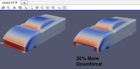
Just to try the effect I made a really simple GT sportscar model and ran it through CFD using the Khamsin Sketch plugin... The car with the "radiused floor inlet" generated 20% more downforce than the one with the "splitter" inlet:

Image

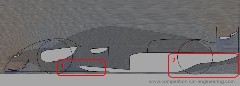
So to bring all that together, I overlayed some suggestions on the section of the Brook Motorsport car...

First step was to superimpose the "Double-inflection-diffuser" onto it (Balloon 2)....

For the leading edge of the floor I added a radiused inlet (Balloon 1). As mentioned in a previous post above, the floor inlet at present looks like it is being affected by its location in the upwash under the front suspension cover (see flow lines and the fact there is a recirculation zone on the upper surface of the floor)... so I pulled the leading edge backward to avoid the low pressure generated by the suspension fairing....

Image

(Obviously the flow lines in the image above correspond with the last iteration of the car, and not my modifications)...
Last edited by machin on 27 Sep 2015, 17:20, edited 2 times in total.
COMPETITION CAR ENGINEERING -Home of VIRTUAL STOPWATCH

User avatar
RicME85
52
Joined: 09 Feb 2012, 13:11
Location: Derby

Re: [KVRC ~ish] CCE LMP01

Post

I'm away for the night but will get back on this tomorrow.

Can move the floor back as much as we want as long as the flat floor guides are adhered to.

Variante - are you still using the scooped and rotated L shape for the front suspension cover? I noticed it in an early --- Chris did when he was doing those slices (also where I got the profile of your diffuser from)

I can have one more change lined up, I have a better modelled rear wheel pod as I thing the current one is where some issues with OCCFD is coming from. It will also be better for if we do a with/without sides blocked comparison.

User avatar
machin
162
Joined: 25 Nov 2008, 14:45

Re: [KVRC ~ish] CCE LMP01

Post

RicME85 wrote:Variante - are you still using the scooped and rotated L shape for the front suspension cover? I noticed it in an early --- Chris did when he was doing those slices (also where I got the profile of your diffuser from).
I personally would keep with what you've got at the moment: the underside of your fairing is no doubt generating downforce (you can confirm by looking at the surface pressures?).. Its also nicely faired so should be low drag....

But most importantly: Any changes to the front end now will potentially mask any changes you make at the rear... so you won't now what has worked and what hasn't....
COMPETITION CAR ENGINEERING -Home of VIRTUAL STOPWATCH

User avatar
variante
138
Joined: 09 Apr 2012, 11:36
Location: Monza

Re: [KVRC ~ish] CCE LMP01

Post

RicME85 wrote:Variante - are you still using the scooped and rotated L shape for the front suspension cover?
https://ef1f5a3b-a-91d86b73-s-sites.goo ... edirects=0
I've been using these suspension covers for the first half of the champioship. Notice the angle given to the airflow leaving the covers: it's pretty much zero, so it doesn't mess up the downstream airflow.

The last iteration of my car features front cover not enclosing the suspesion, of similar concept to the rear suspension cover. The change is due to the revised cooling inlet templates, which would otherwise intersect the cover. Still, i suspect -but cannot guarantee- that the "open" cover works better than the fully enclosing one.

No Lotus
No Lotus
3
Joined: 26 Jan 2013, 17:22
Location: Reno, NV, USA

Re: [KVRC ~ish] CCE LMP01

Post

I don't know whether it's legal in the competition (certainly it's illegal in LMP racing), but I wonder what the effect of aerodynamic skirts that extend to the ground would be on the underbody downforce. What arrangement would work best? Obviously it will depend upon underbody design, ride height, etc, but would it be better to allow cross flow from the sides of the car or better to completely seal off the underbody? I remember seeing an interview with the designer of the 956 who said that full body length skirts decreased downforce in that car. How about skirts that direct flow around the wheels to speed up underfloor flow?
SCUDERIA FASE
2016 Phase 1