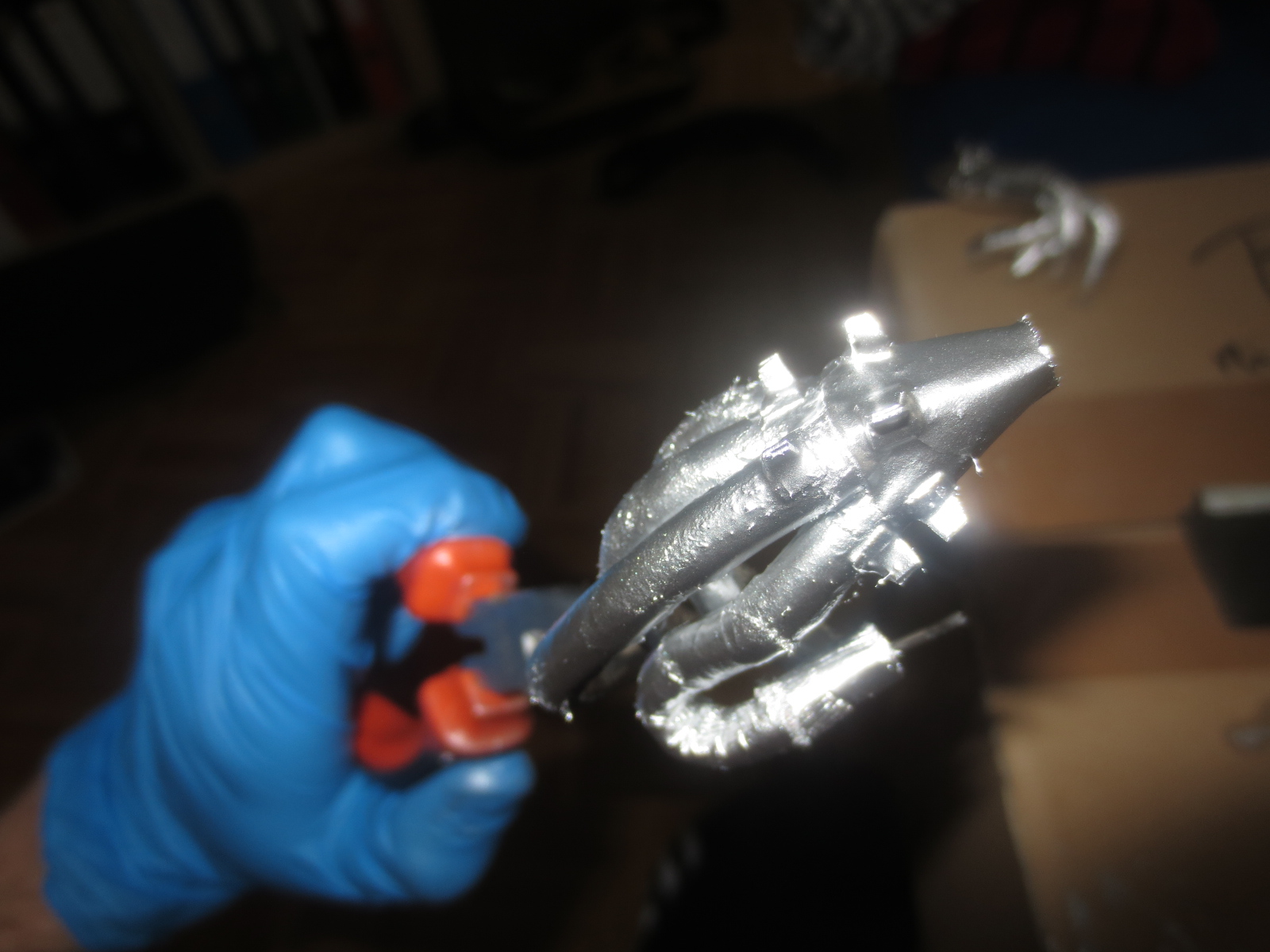
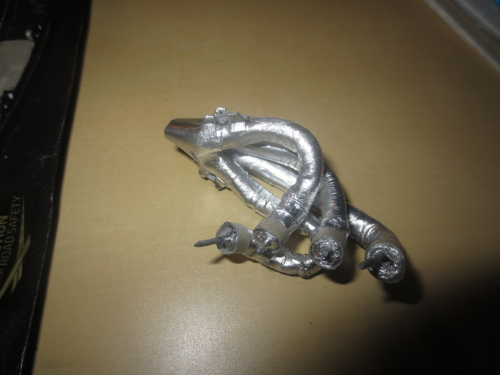
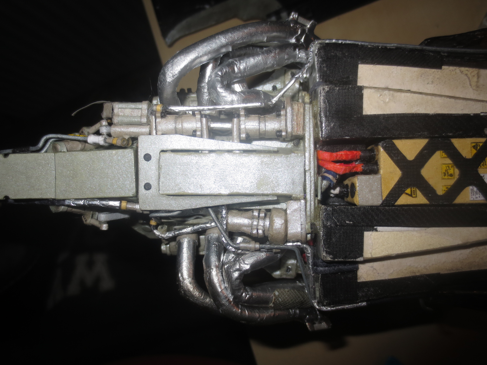
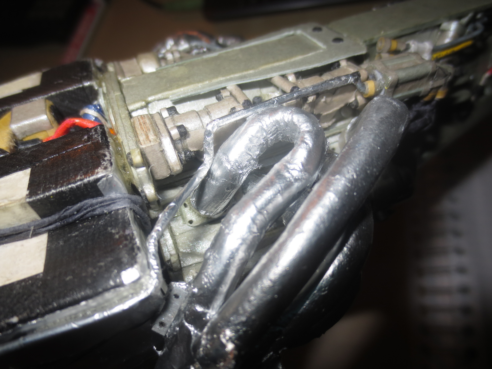
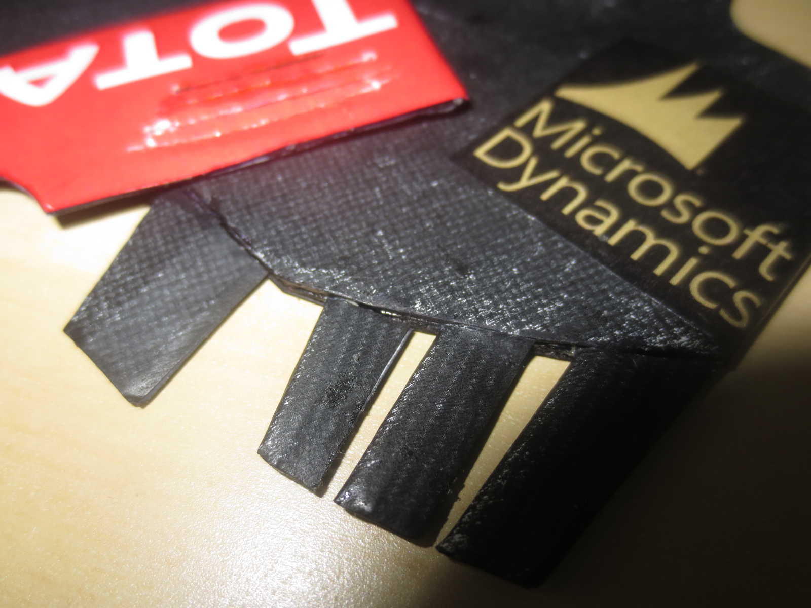
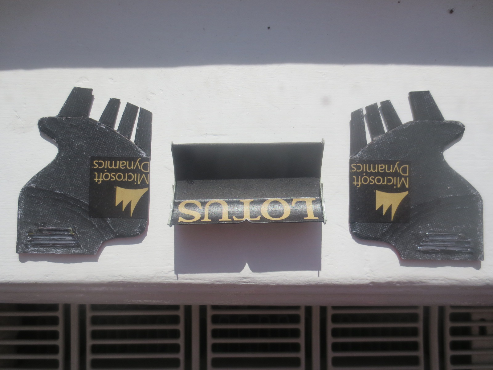
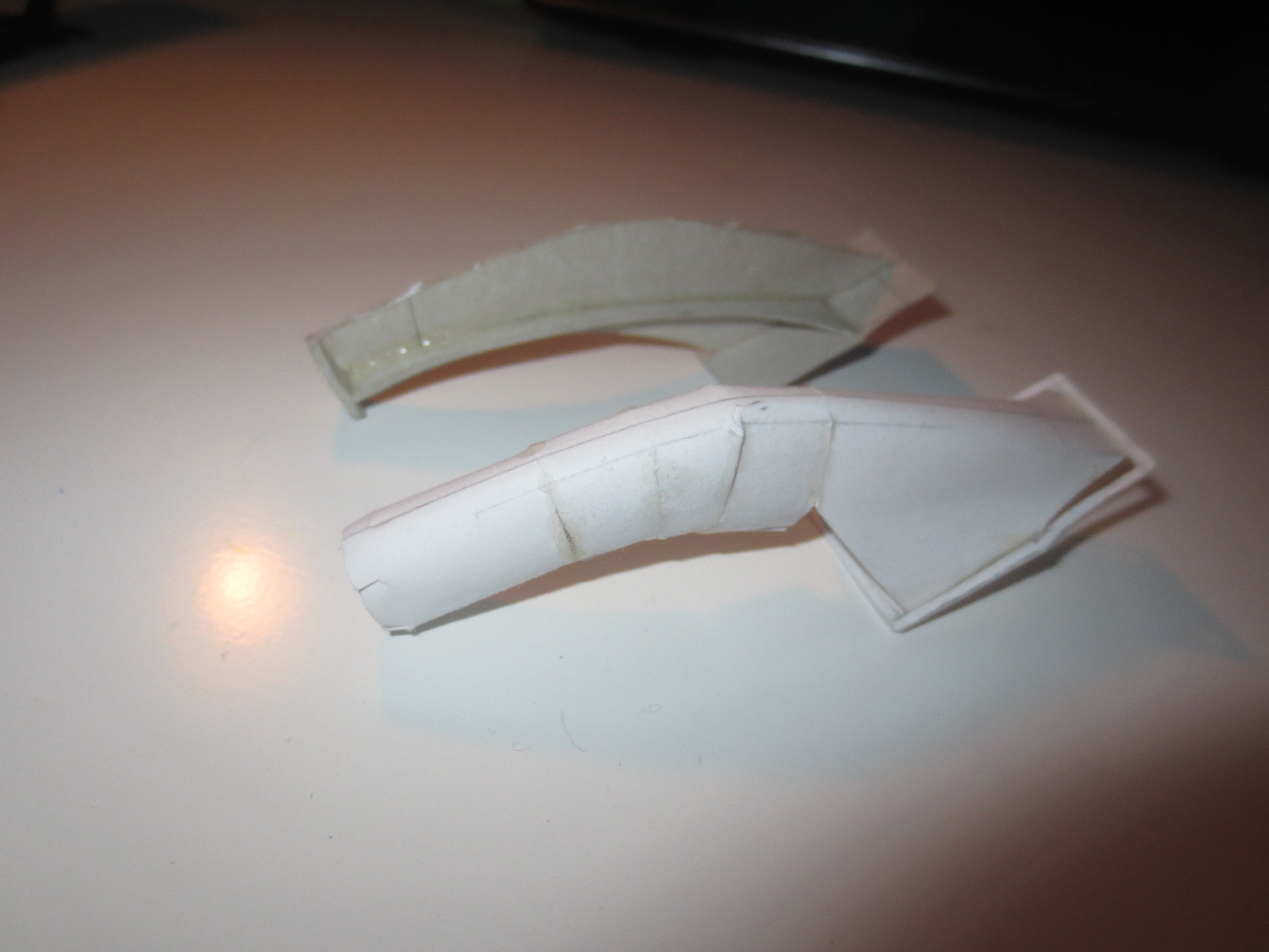
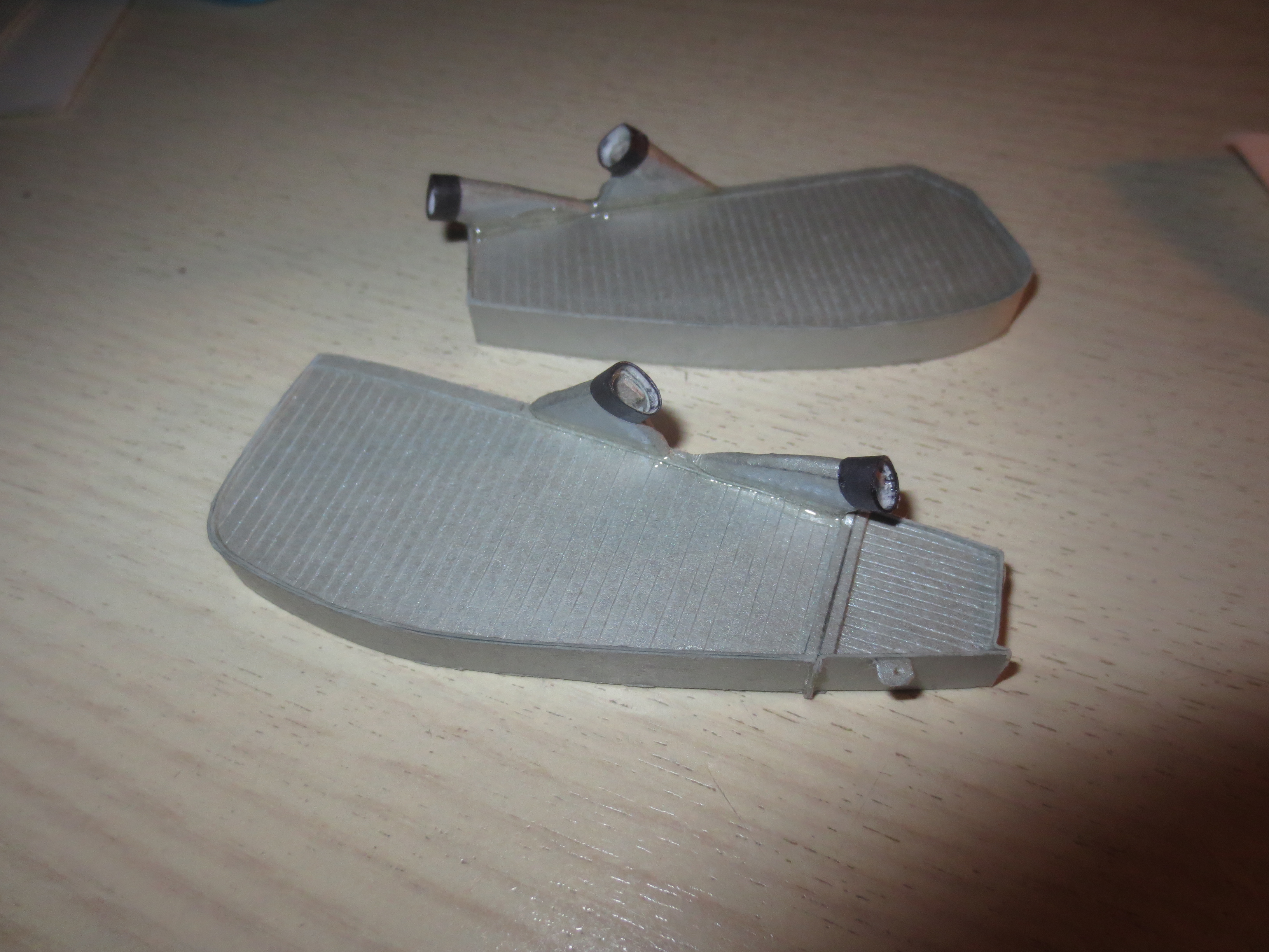
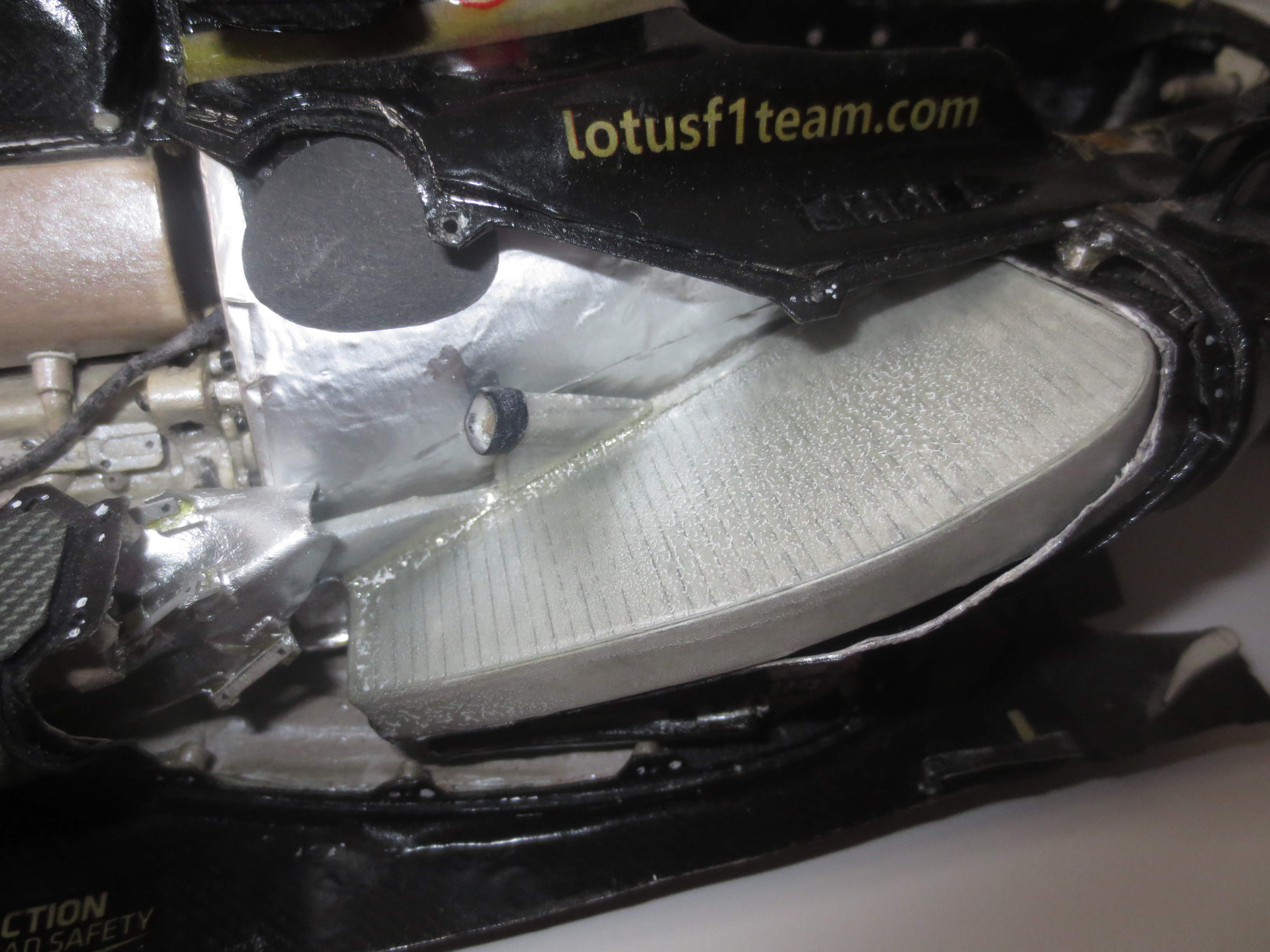
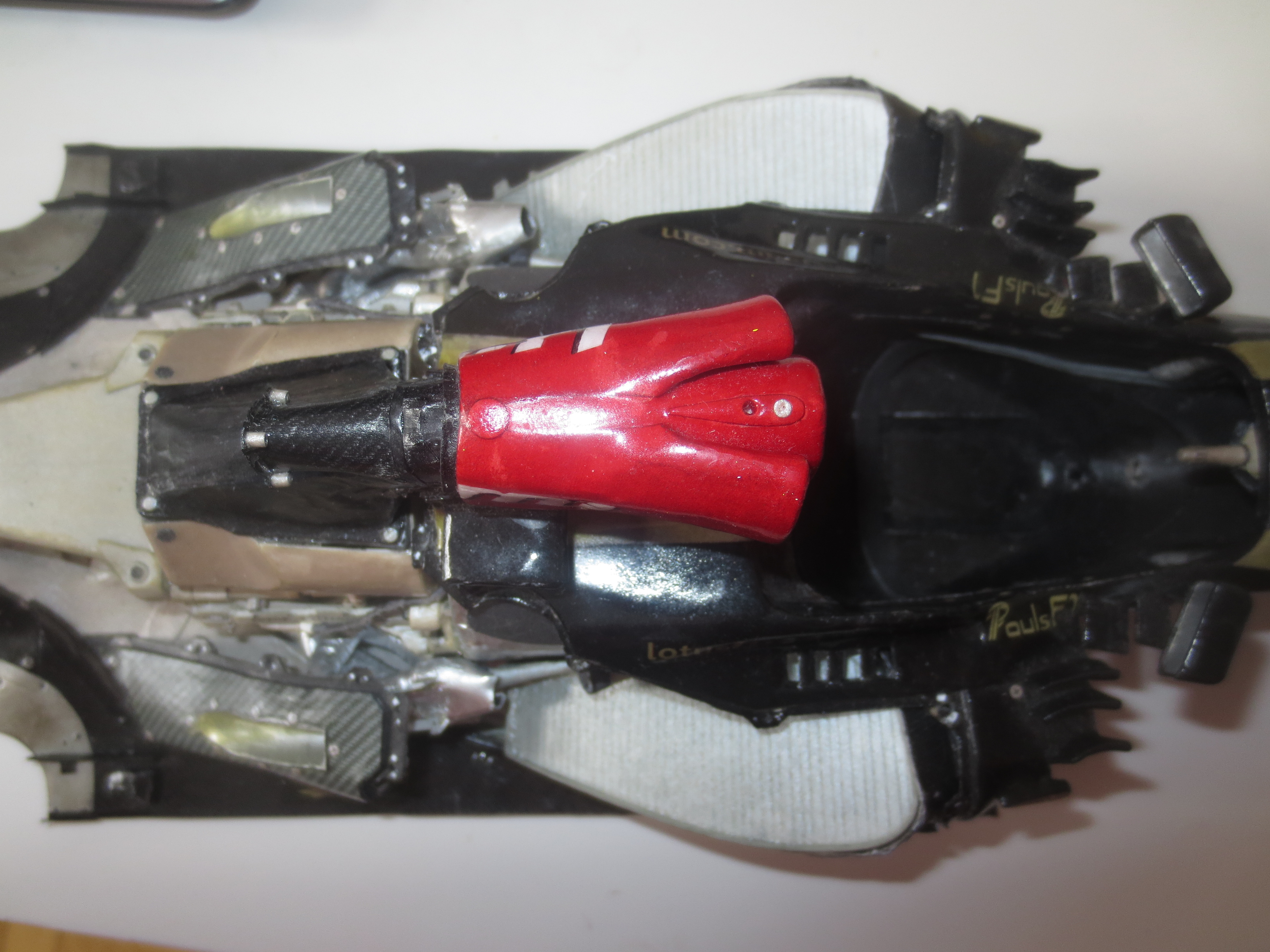
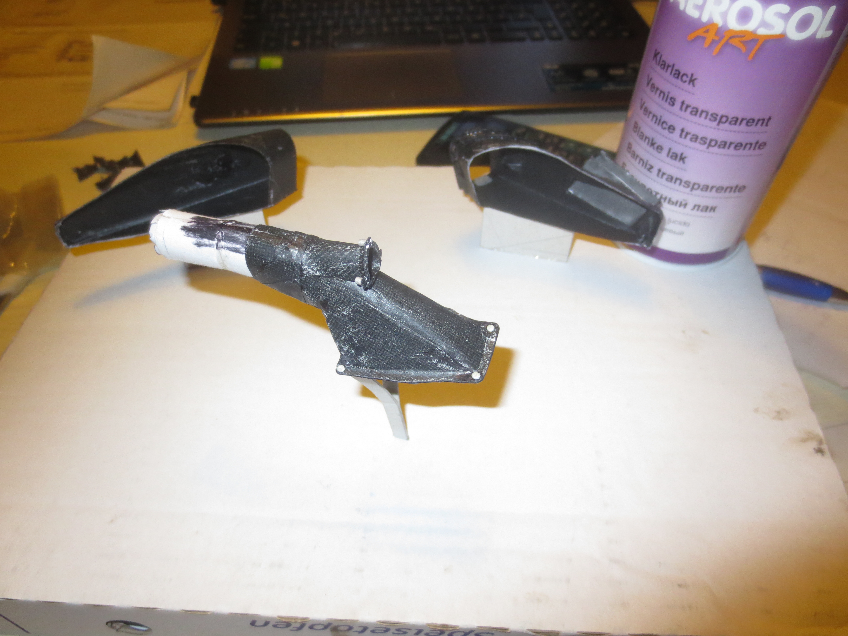
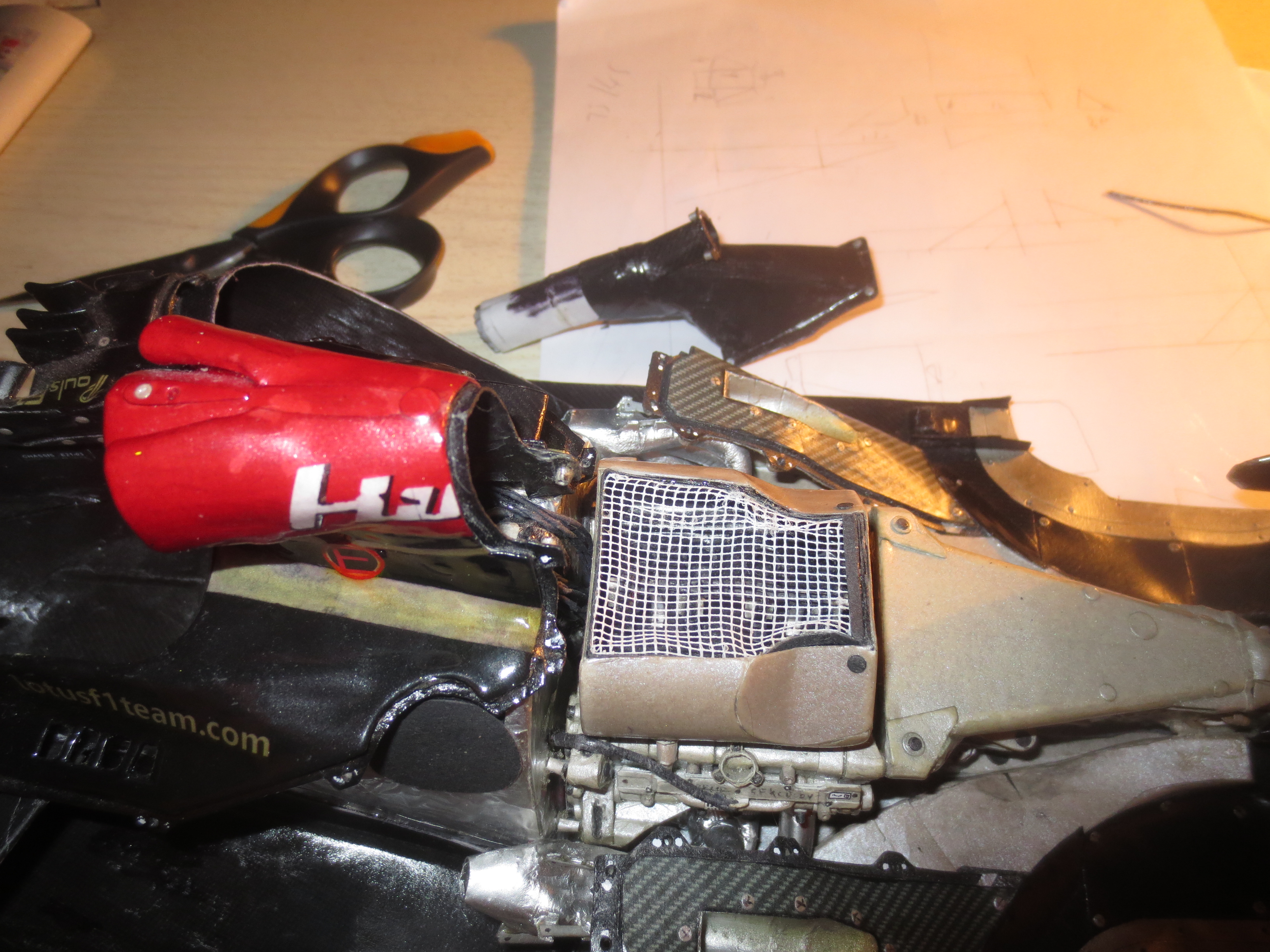
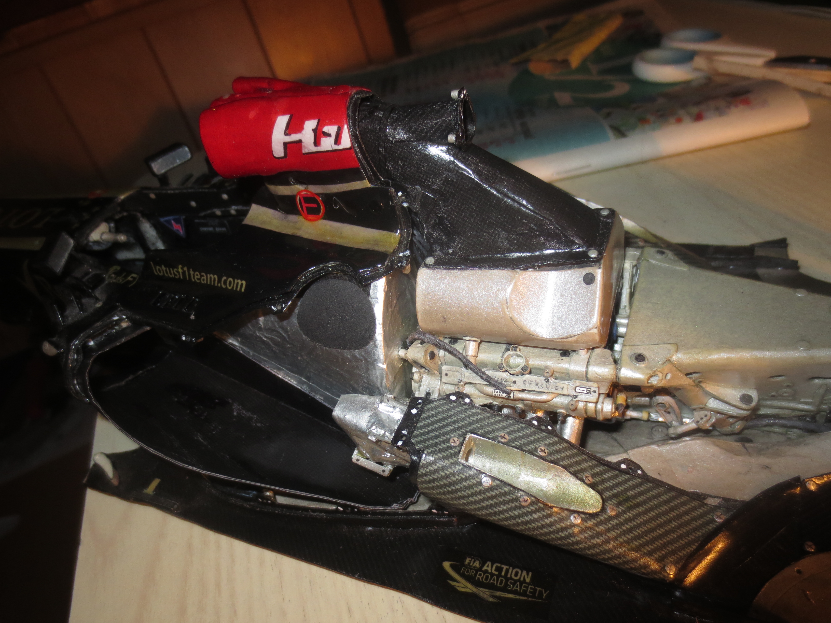
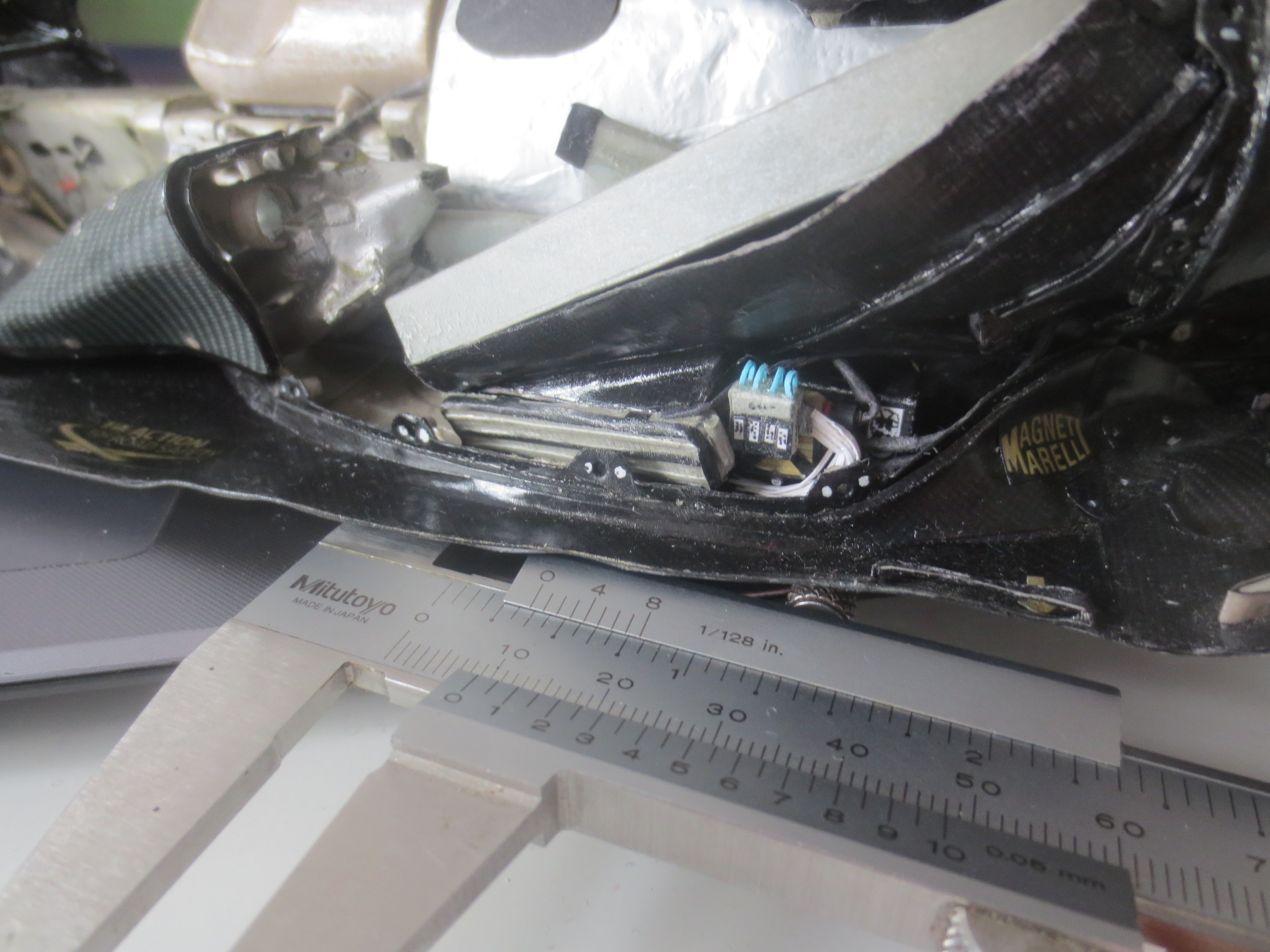
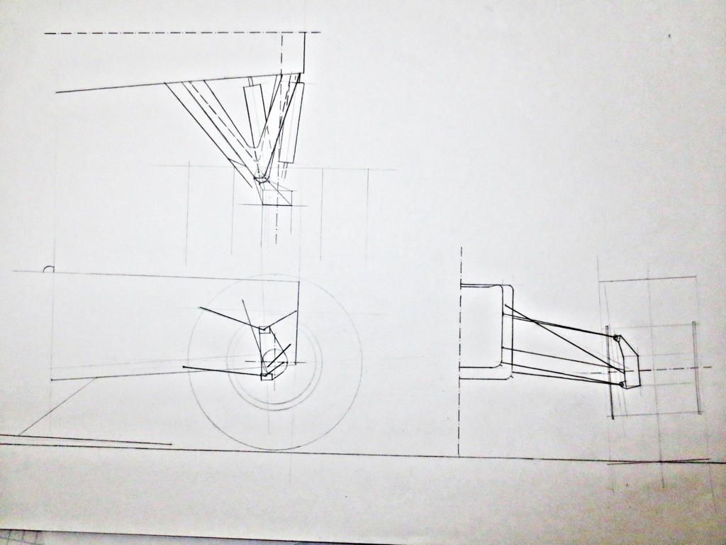
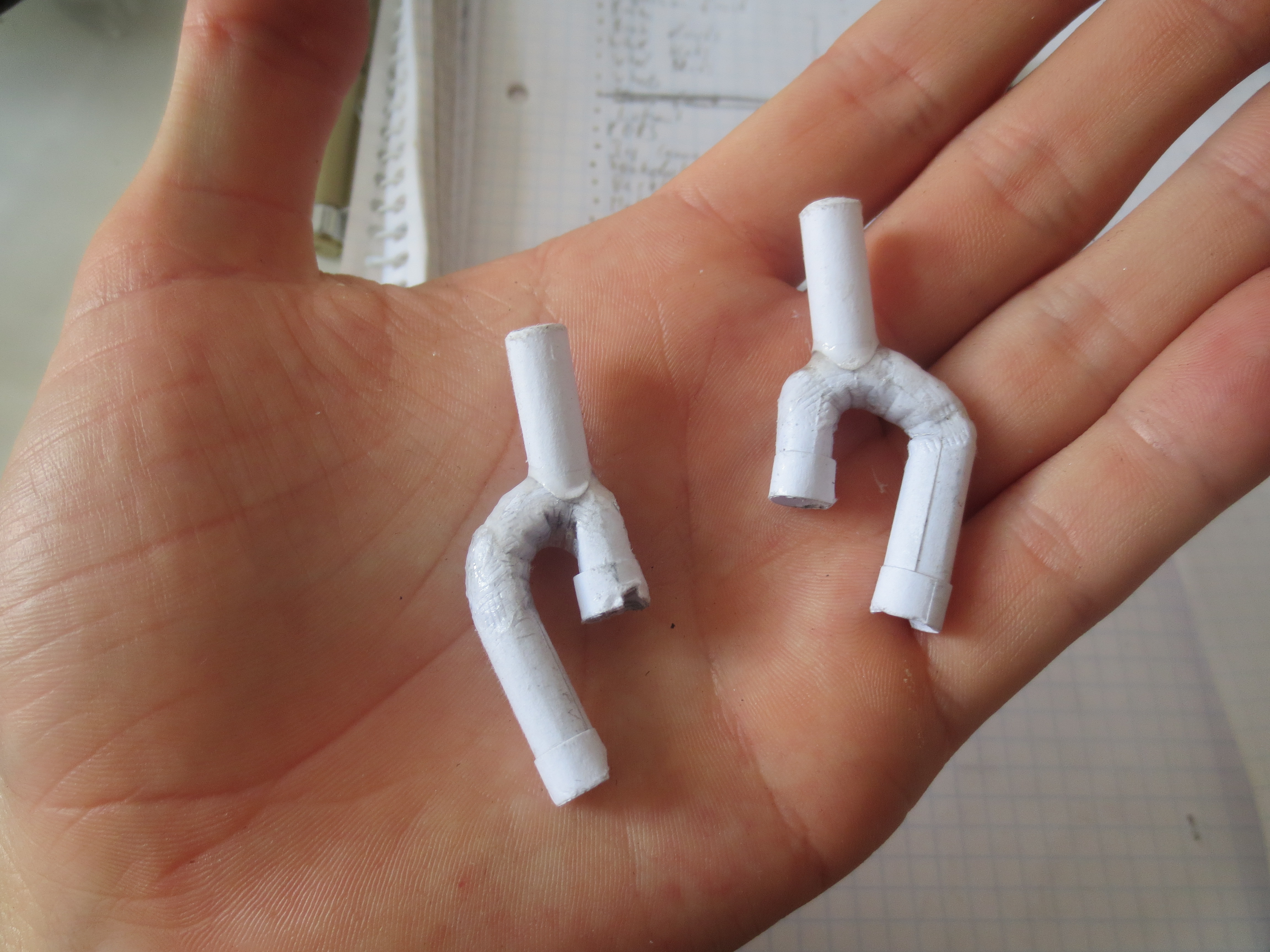
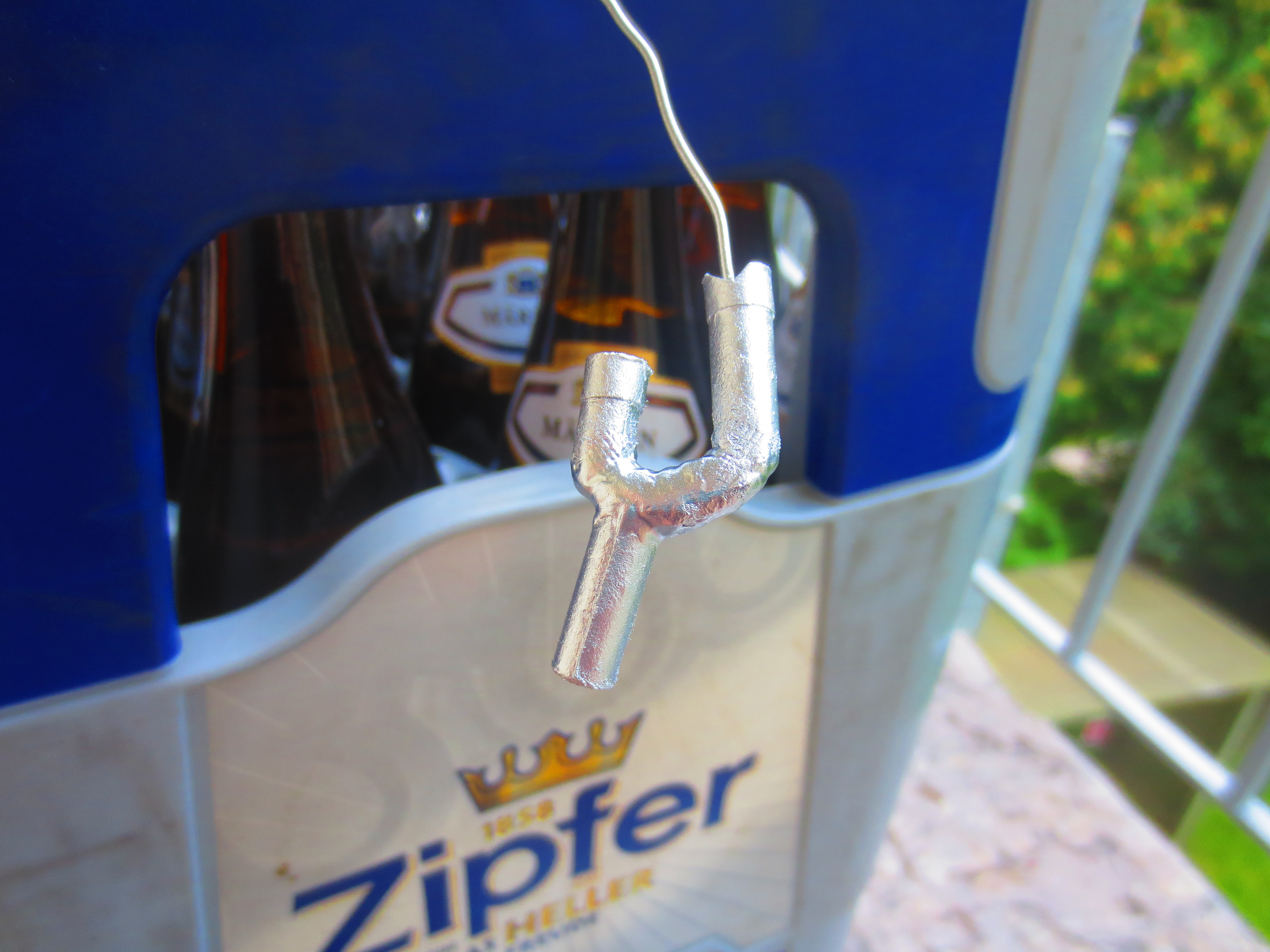
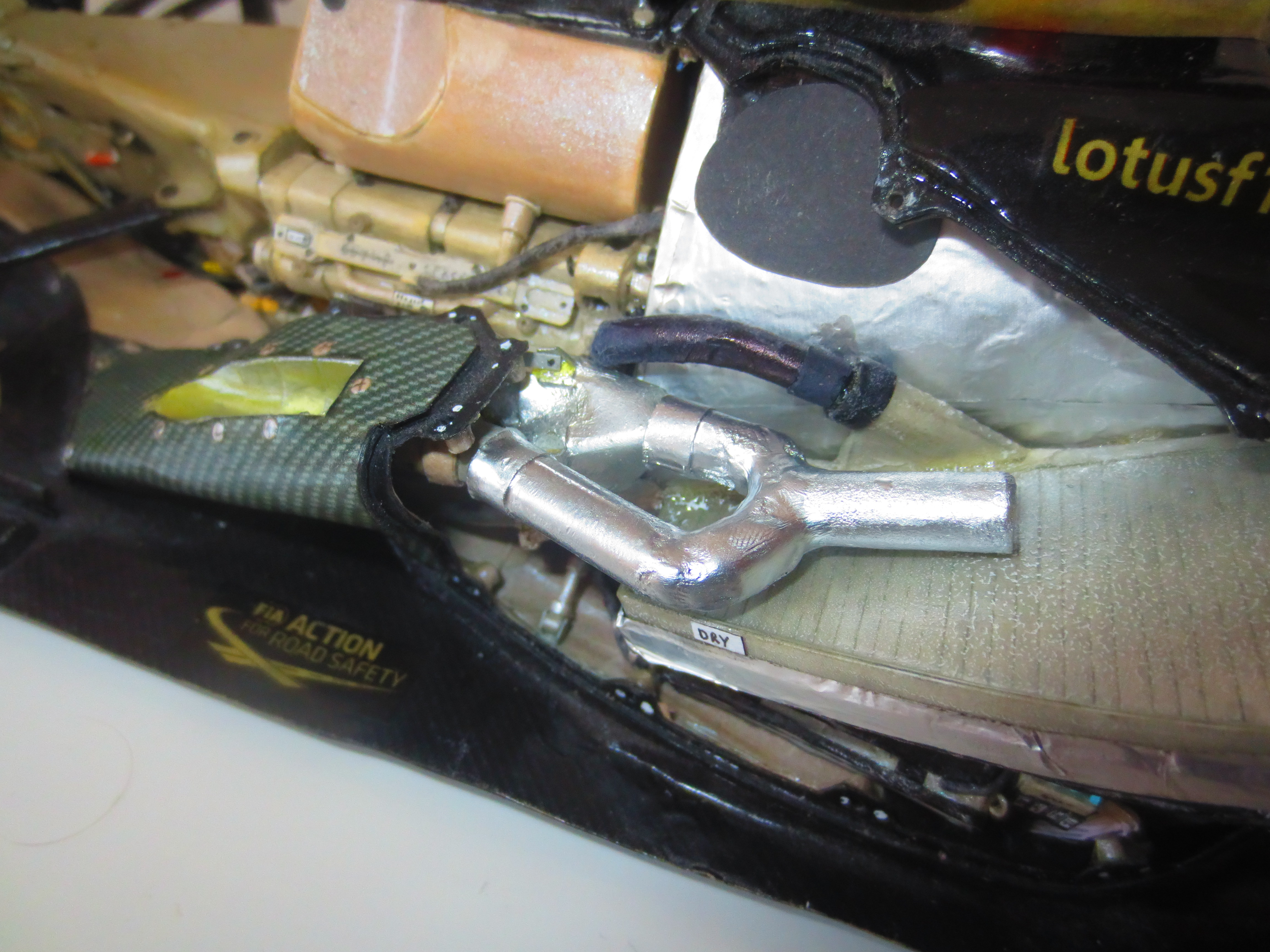
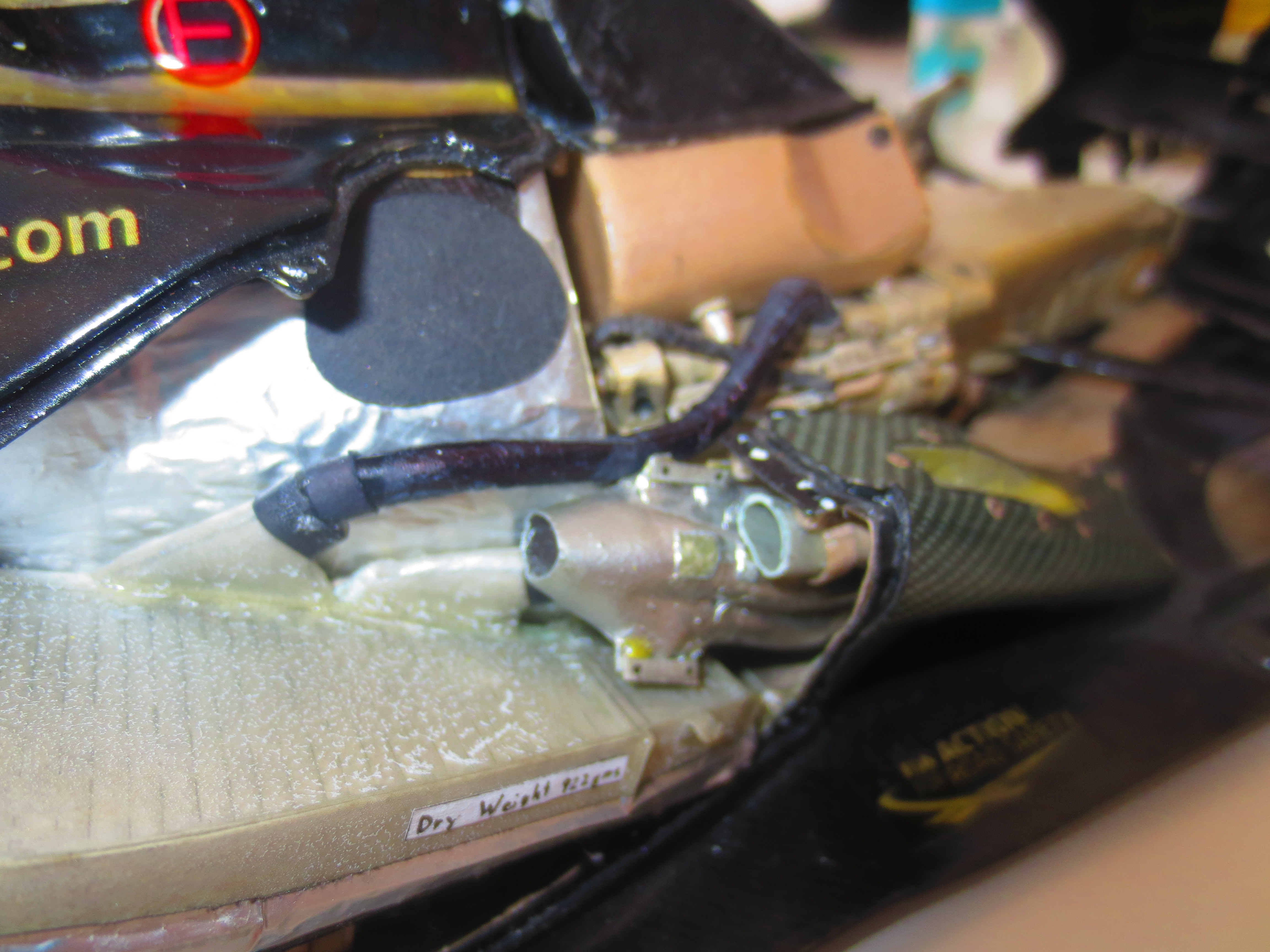
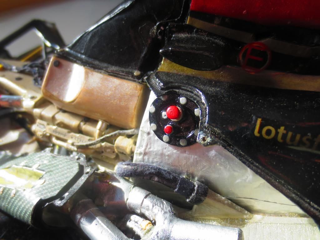
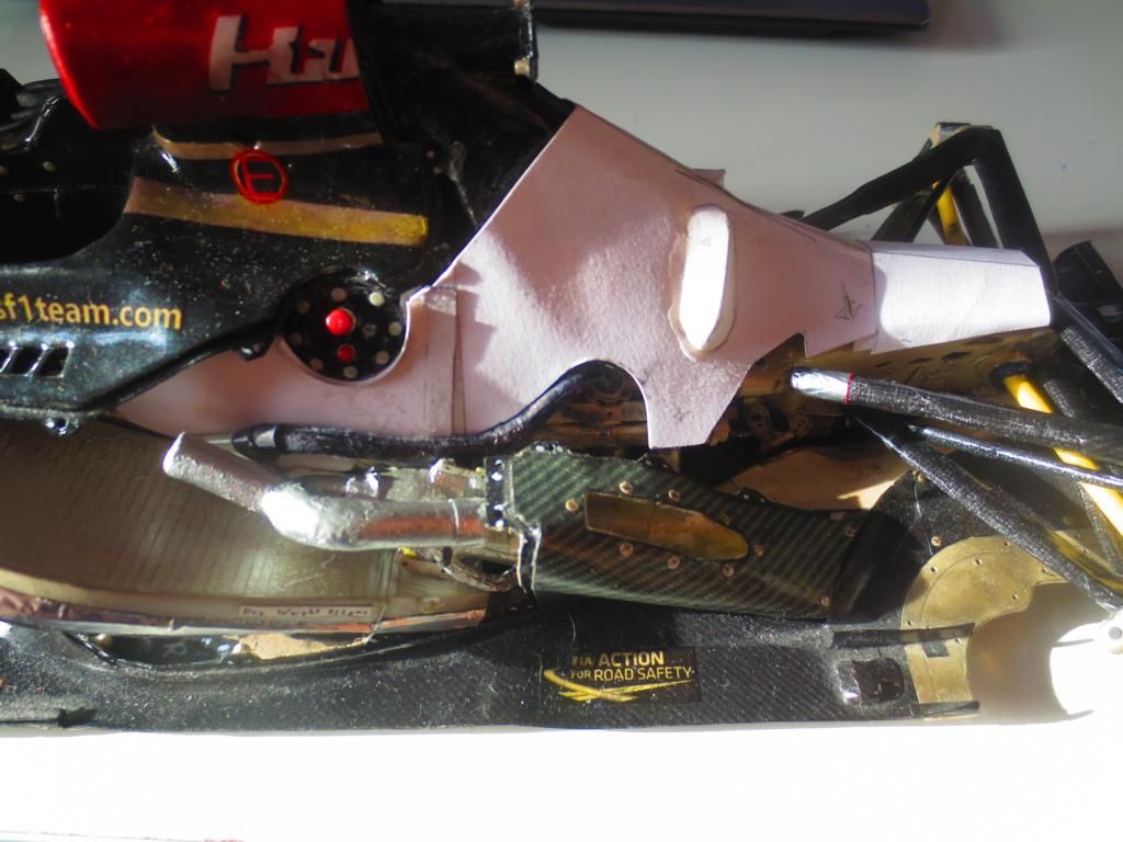
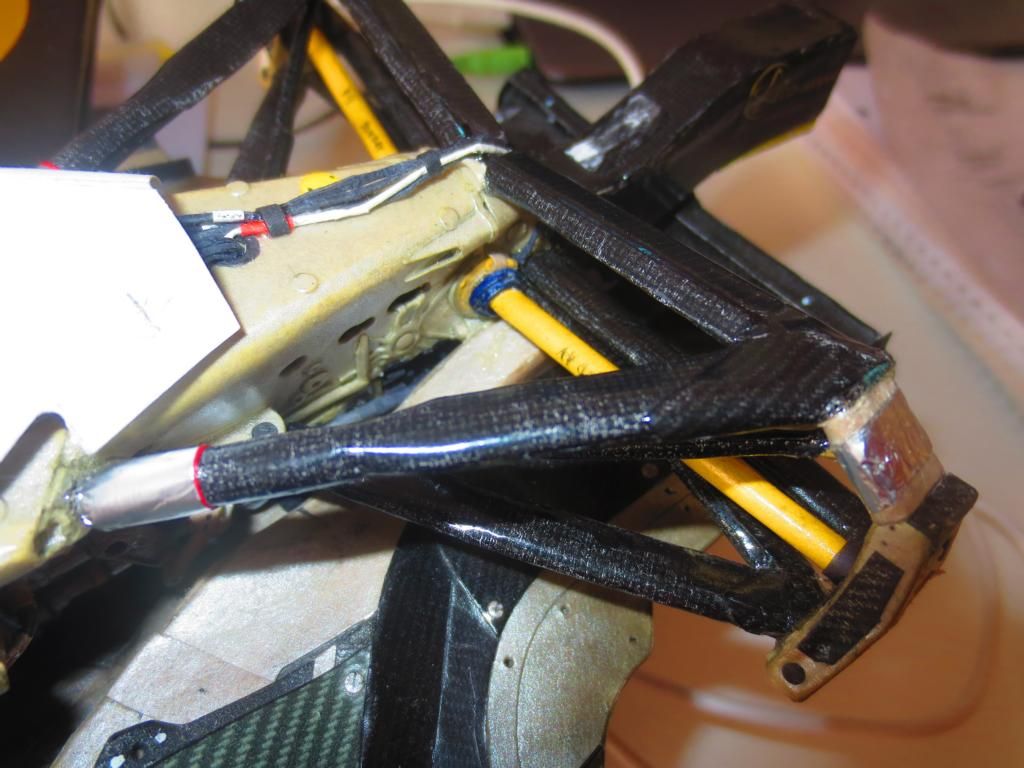
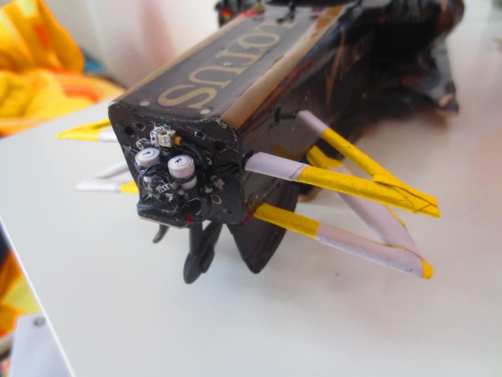
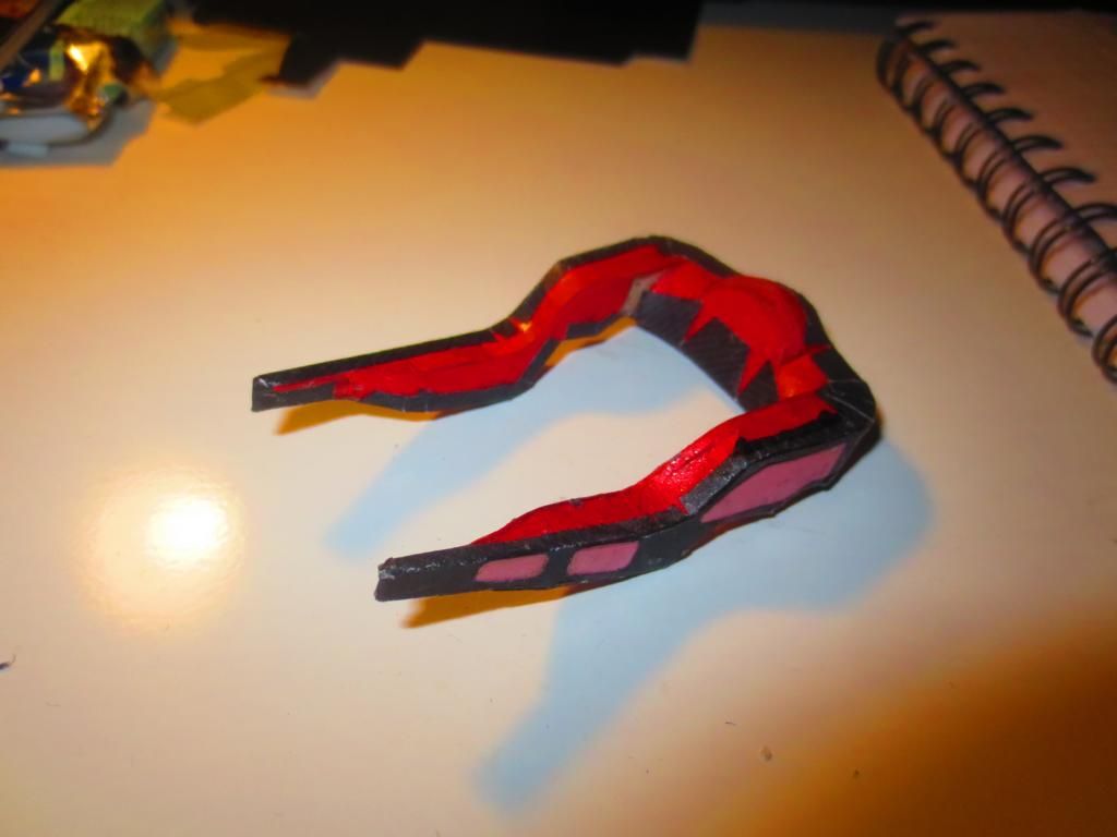
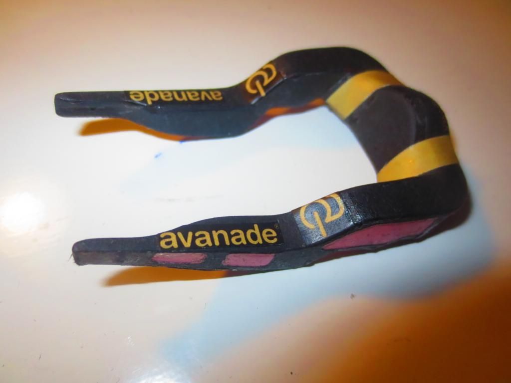
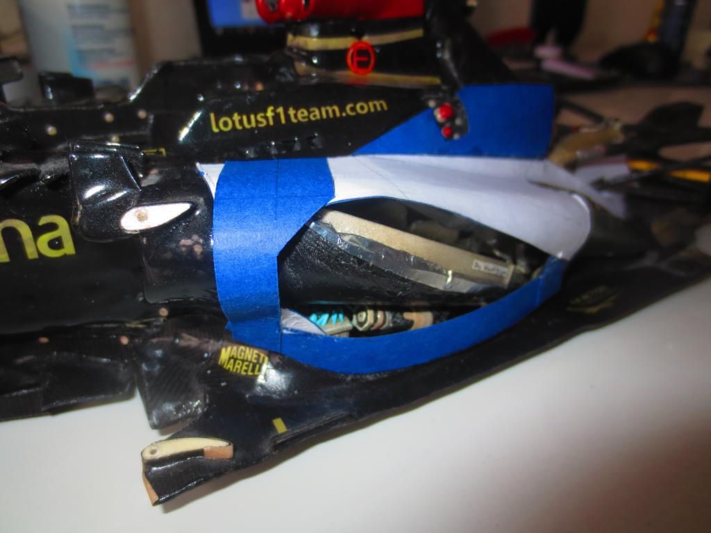
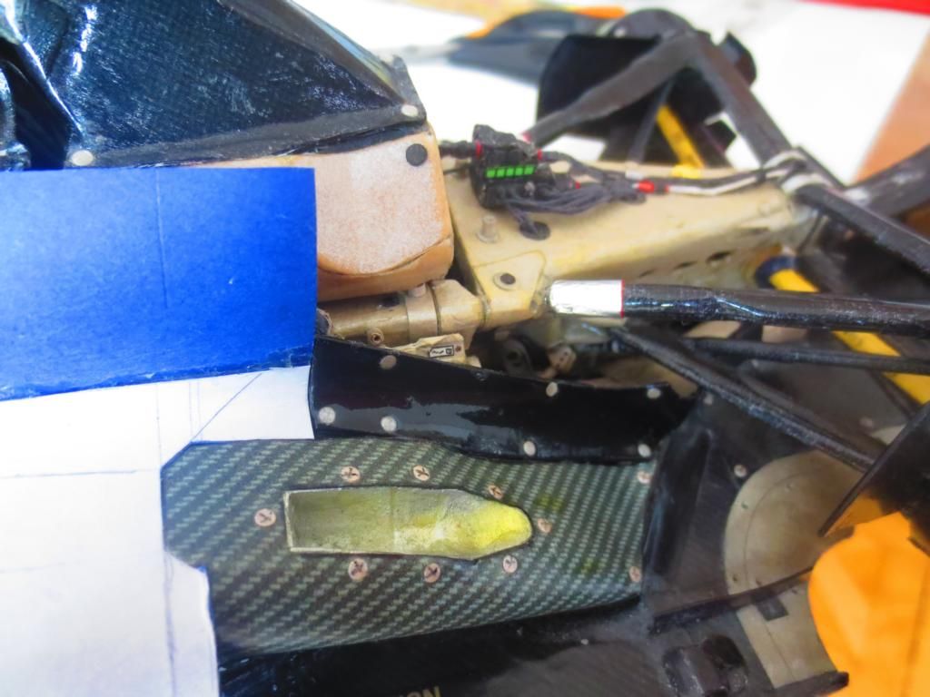
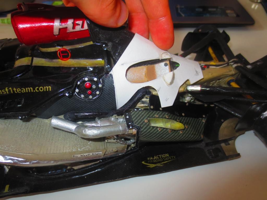
a new episode of my never ending Lotus Project, namely finishing the underbody and Coanda exhaust.
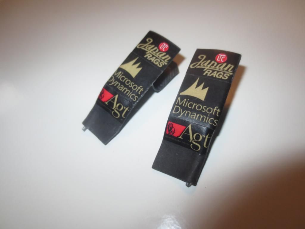
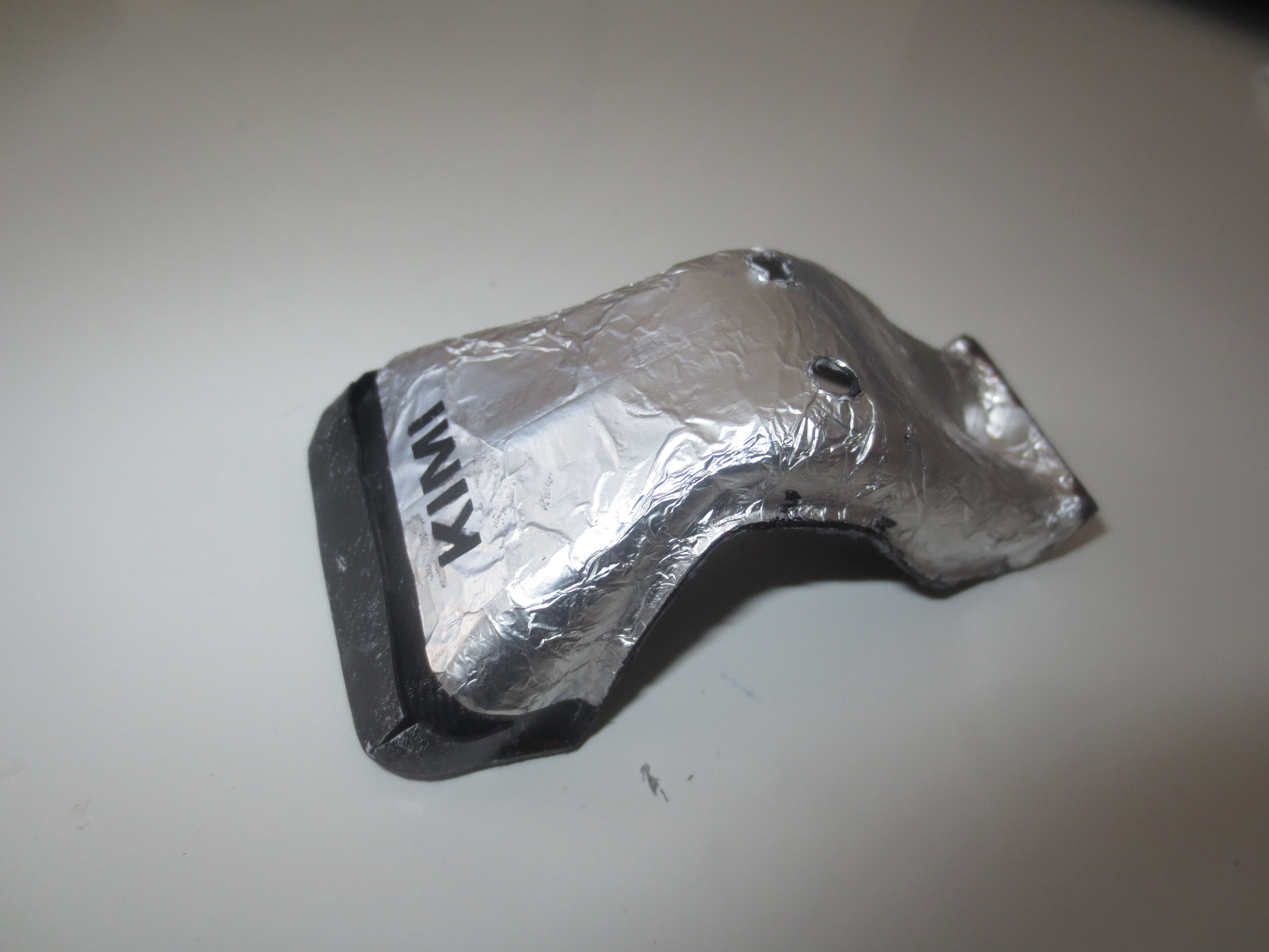
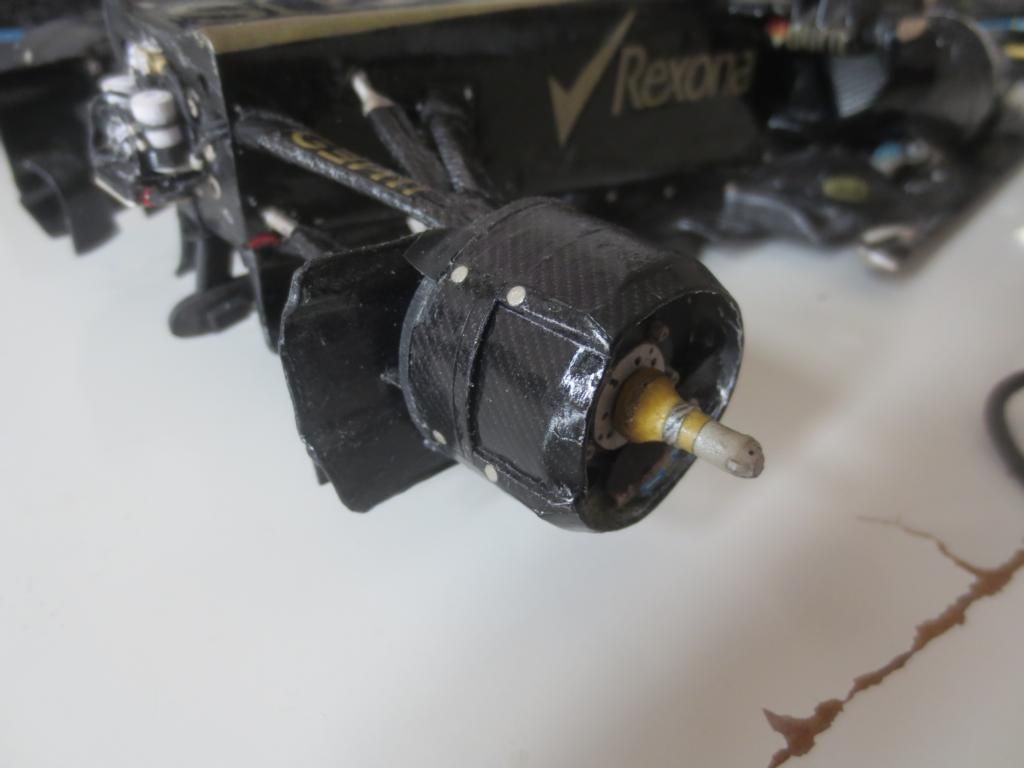
What happened since the last post? Beside manufacturing the Coanda exhausts, where I used a colour spray lacquer (chrome) for the first time, I added loads and loads of small features to the floor. That means stuff like skid blocks, heat shields, IR cam housings, tyre vanes, diffuser strakes, diffuser gurney, live locks, some sponsor/partner labels, reinforcement stuff, bolts, skid planks or CFRP textures.
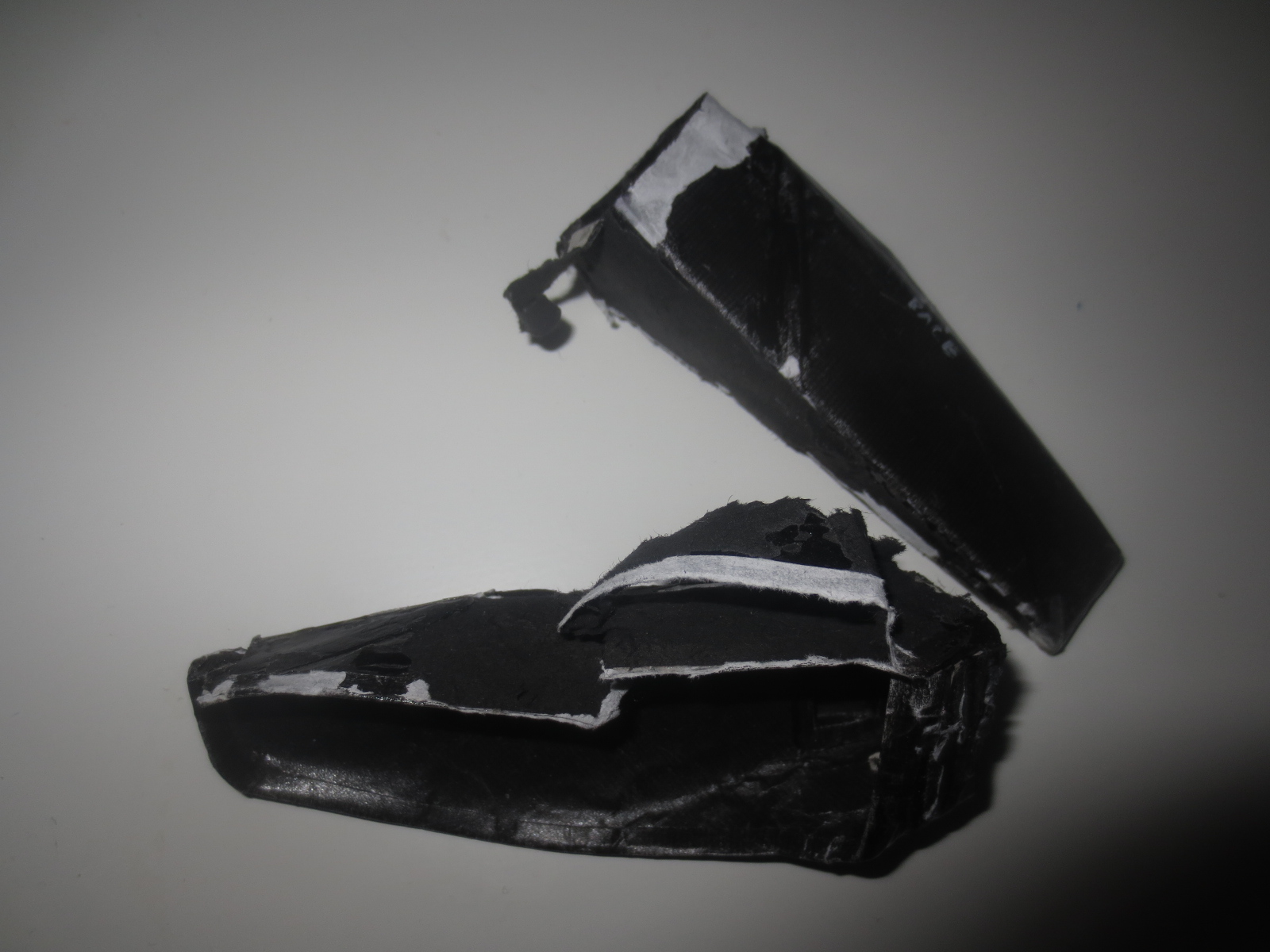
As I mentioned, I introduced some new techniques, namely the chrome spray lacquer for the Coanda exhaust groove for example. After it initially worked flawless, it happened that I run a bit into trouble when applying the final layer of clear lacquer. On the chrome can it says, it's not compatible with clear lacquer, but I thought, clear lacquer will just run off the chrome surface. Instead, it dissolved most of the chrome...
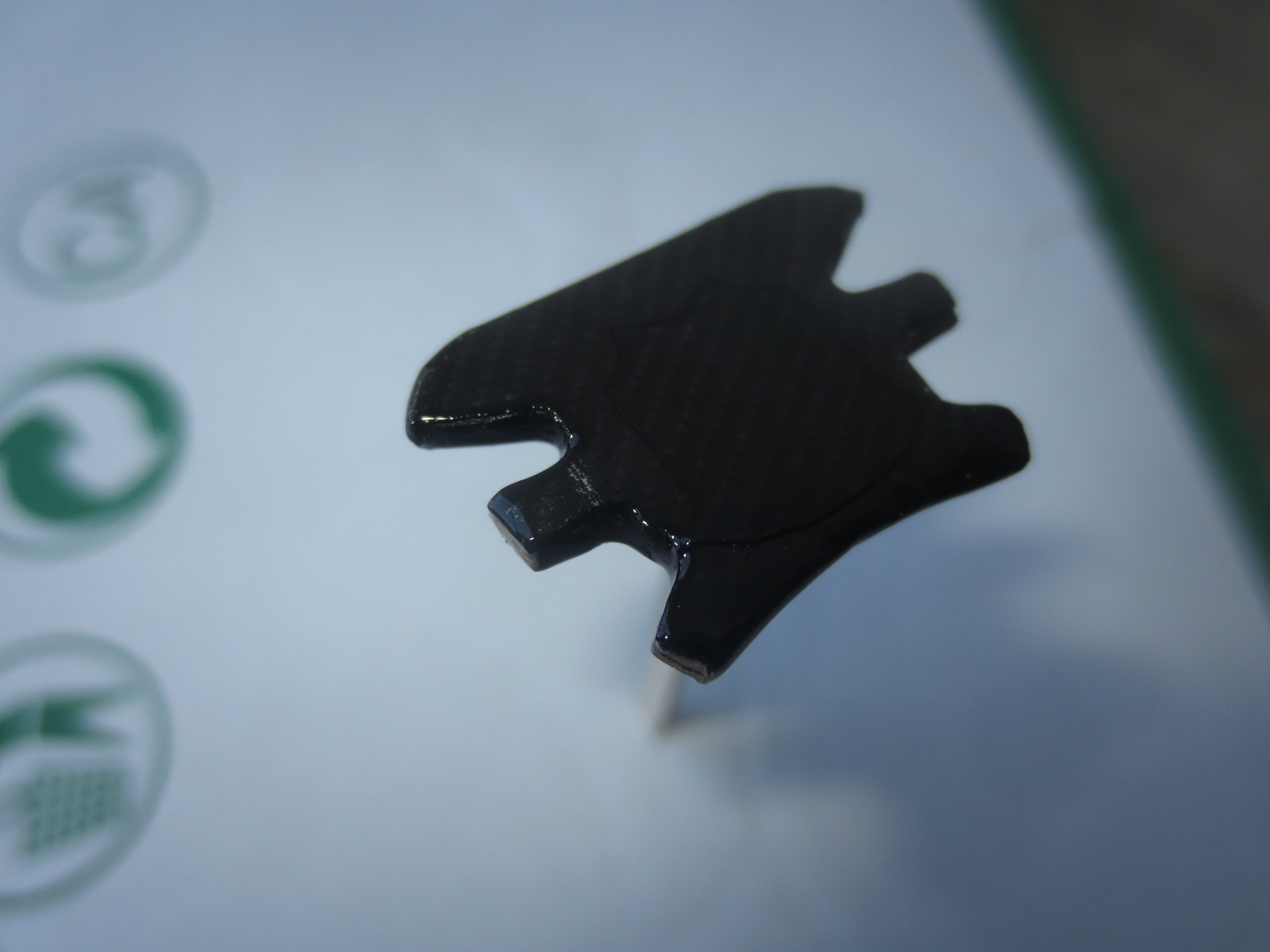
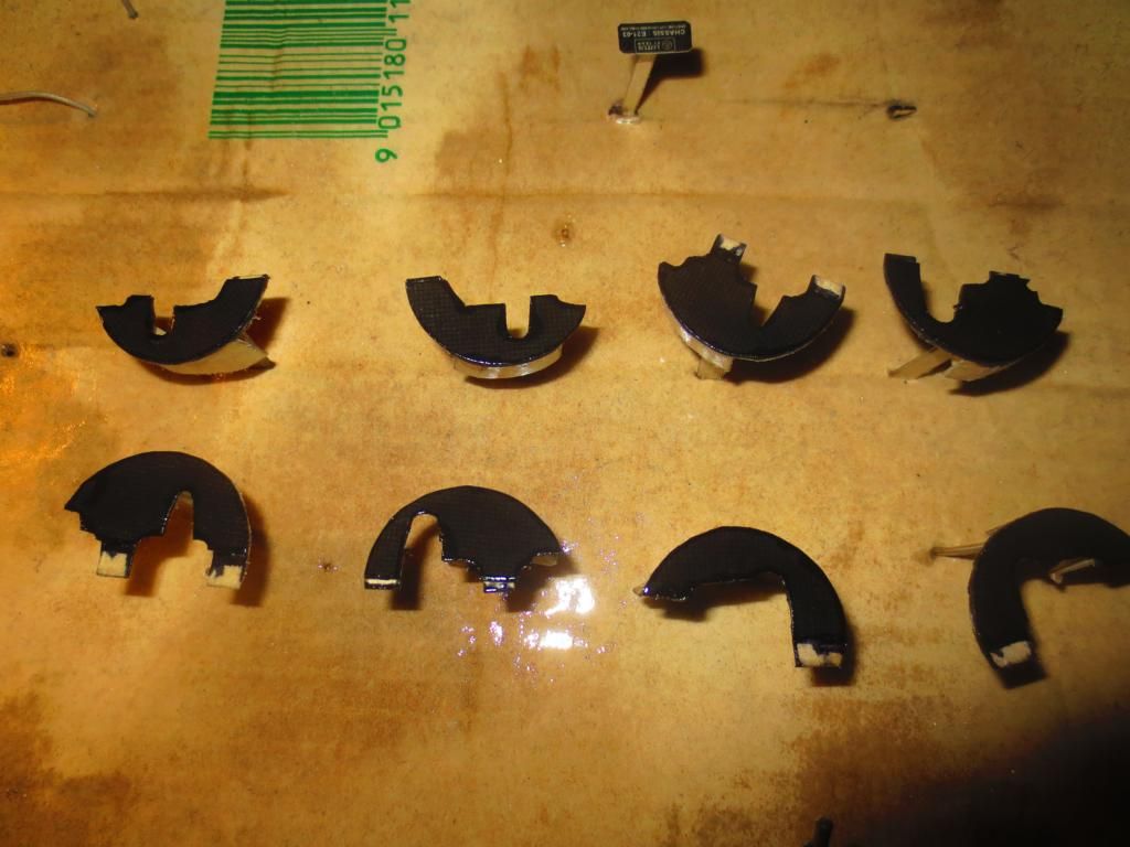
Another new technique was, to use a special glue for applying big-surfaced CFRP areas. Previously, if I bonded on the CFRP texture (90g/m² paper) with my usual glue, it happened that the paper started to dent. The new glue is much less aggressive and does not show this properties.
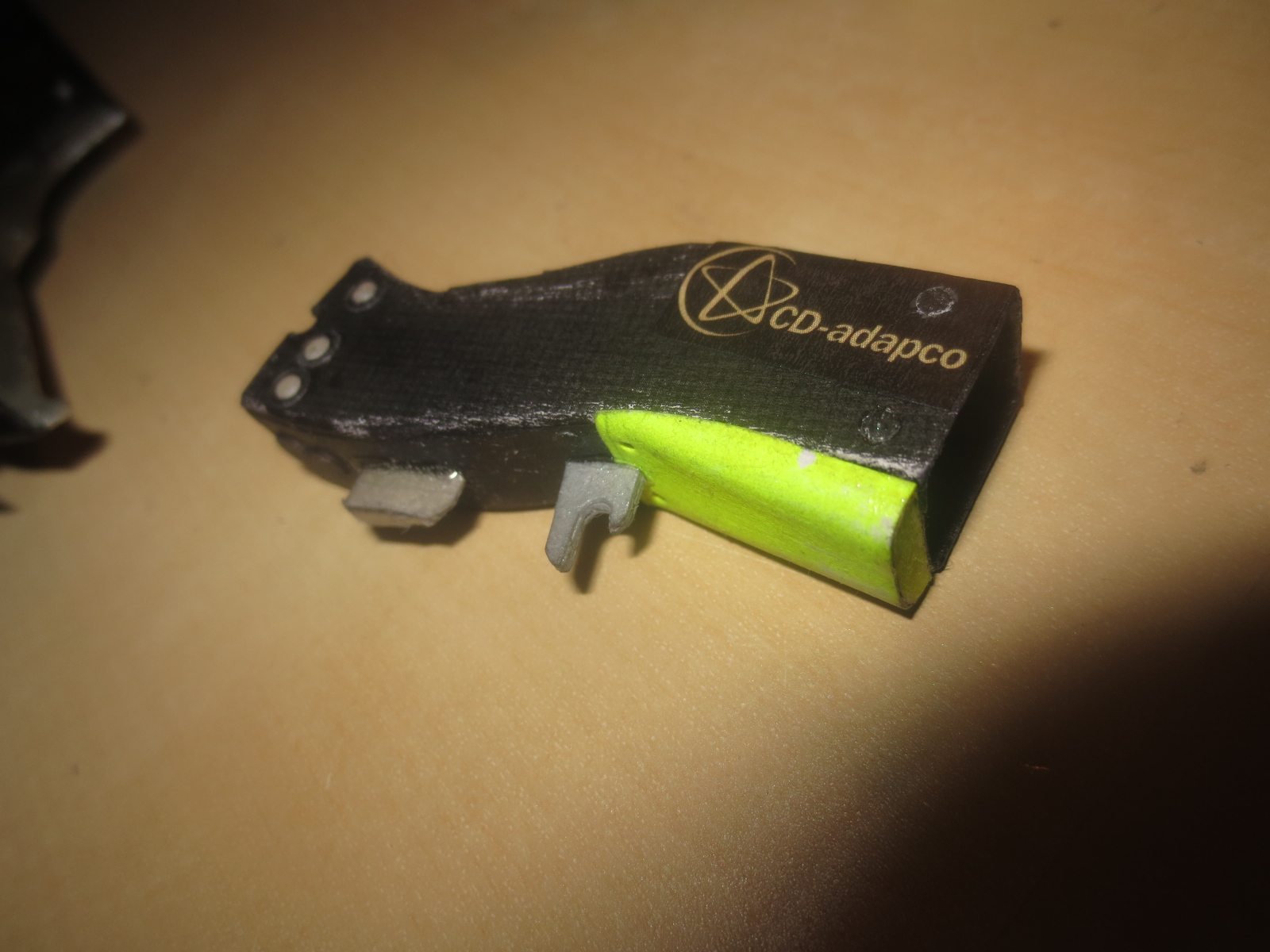
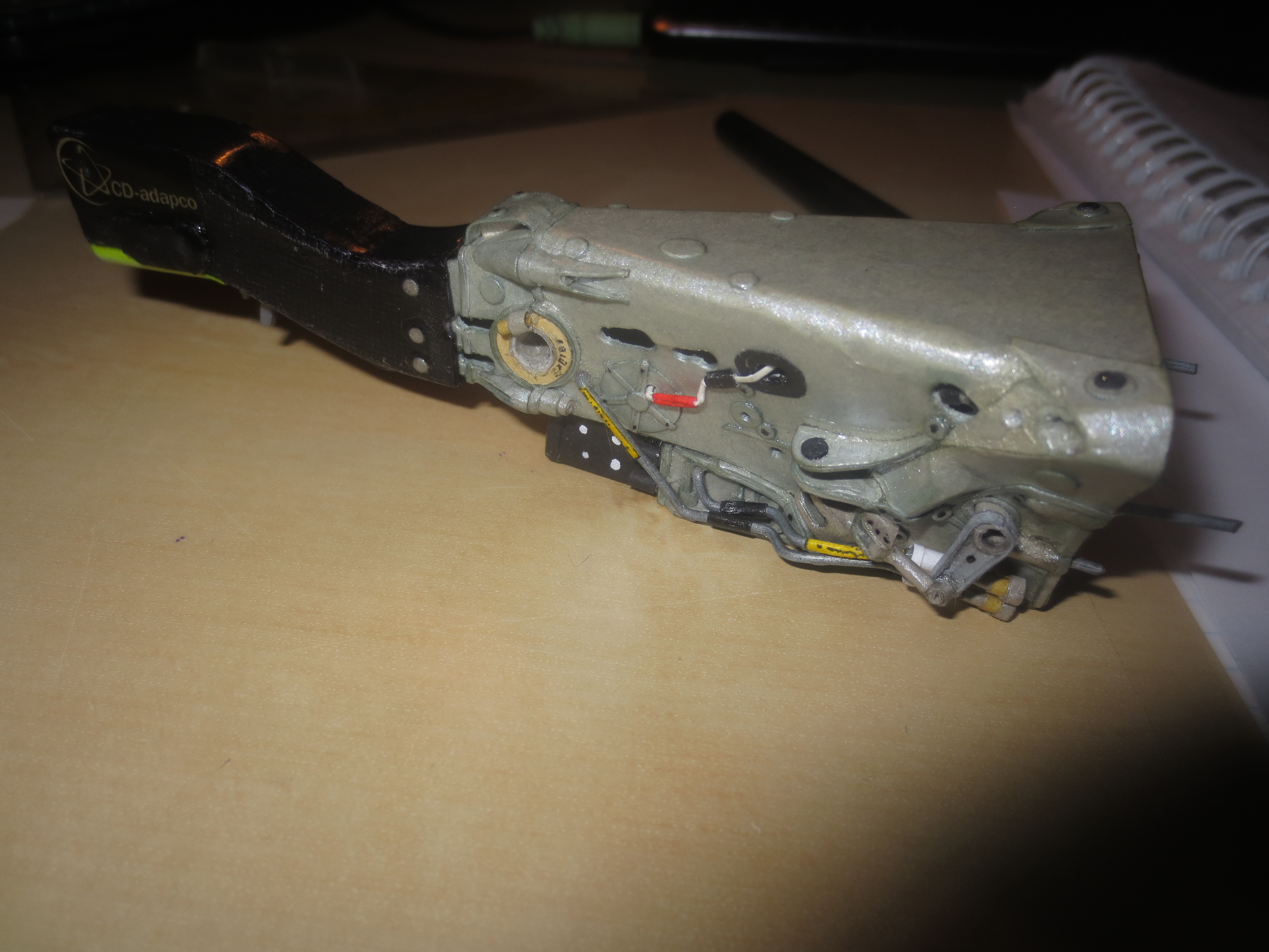
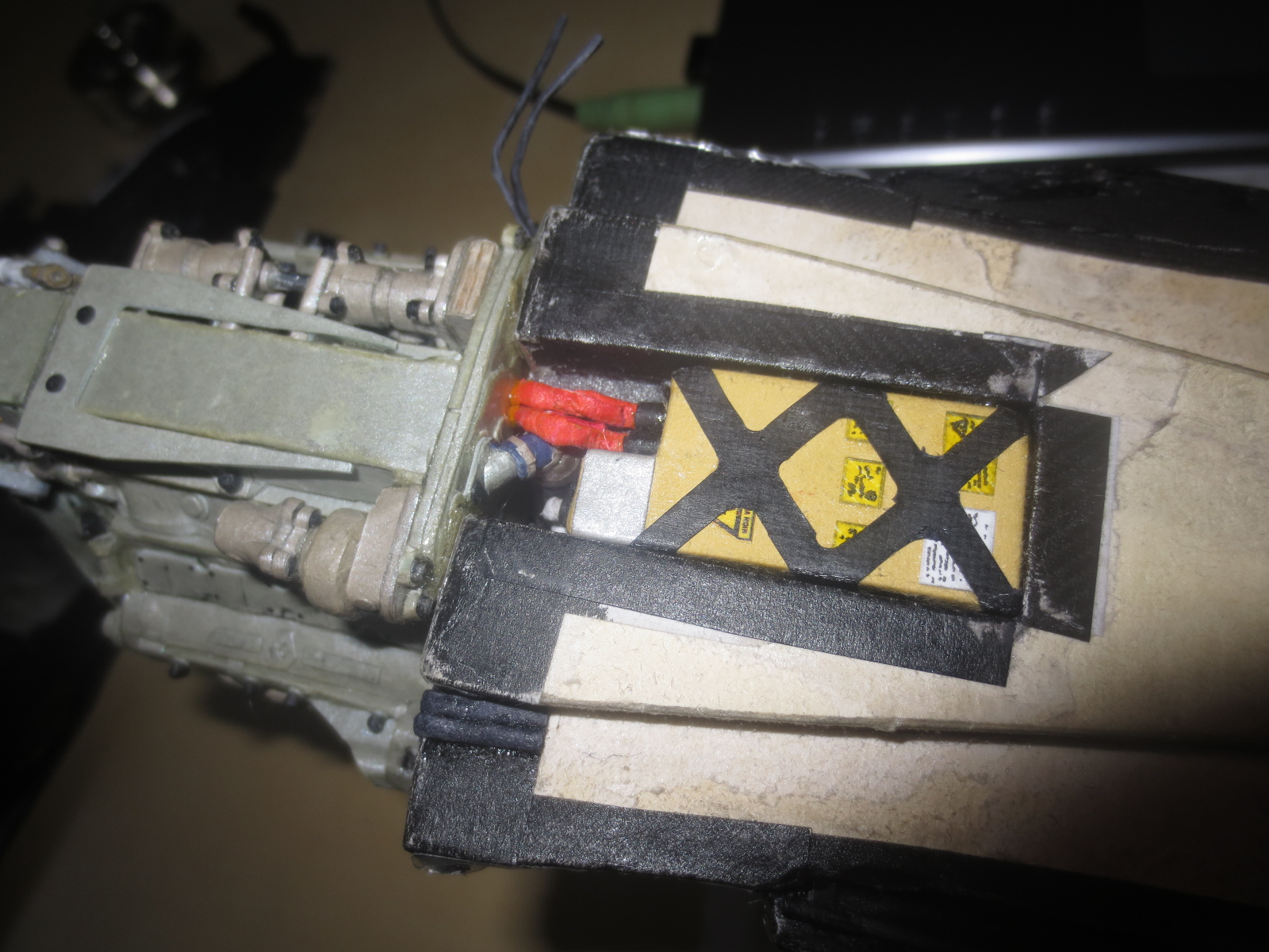
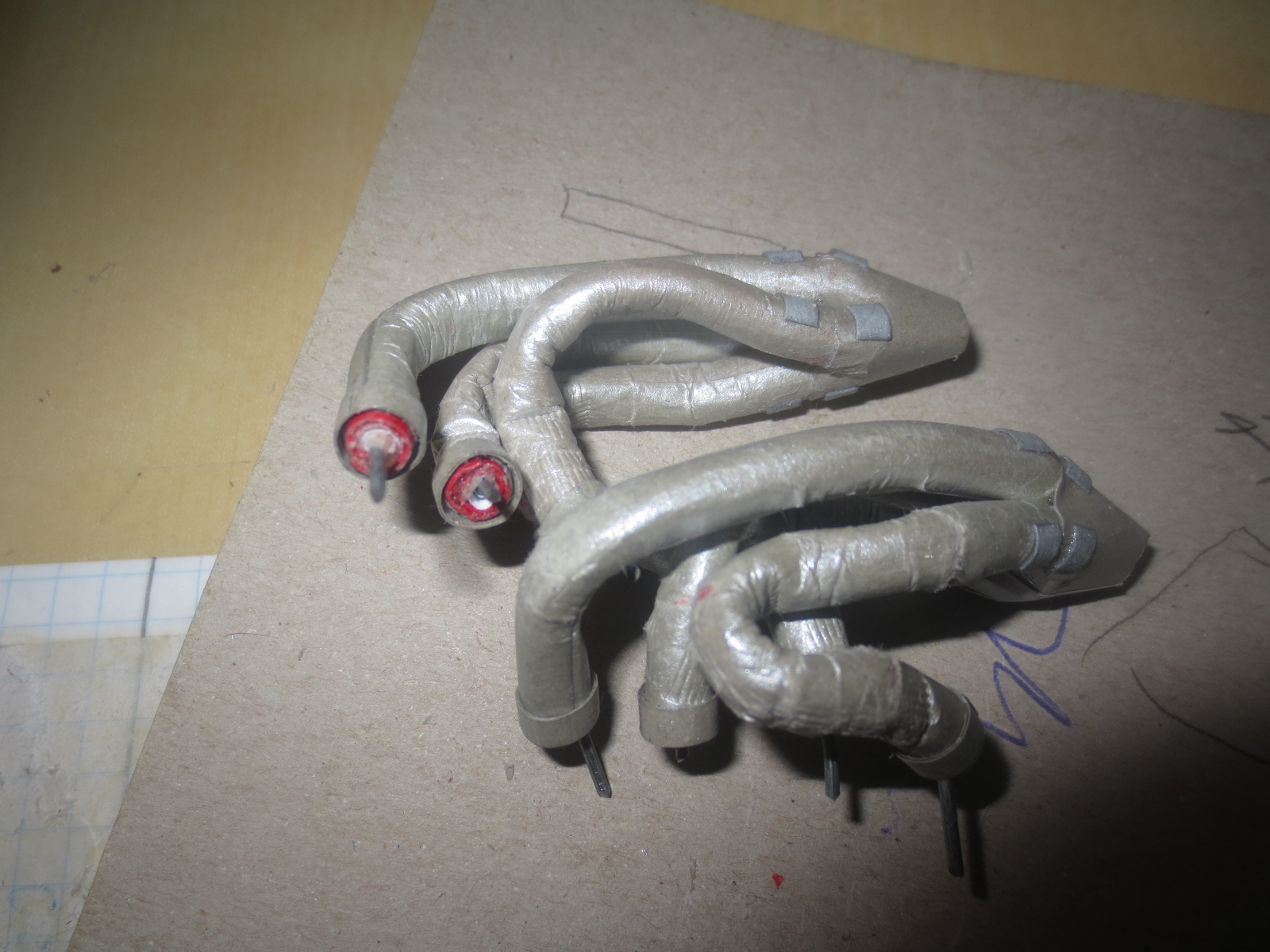
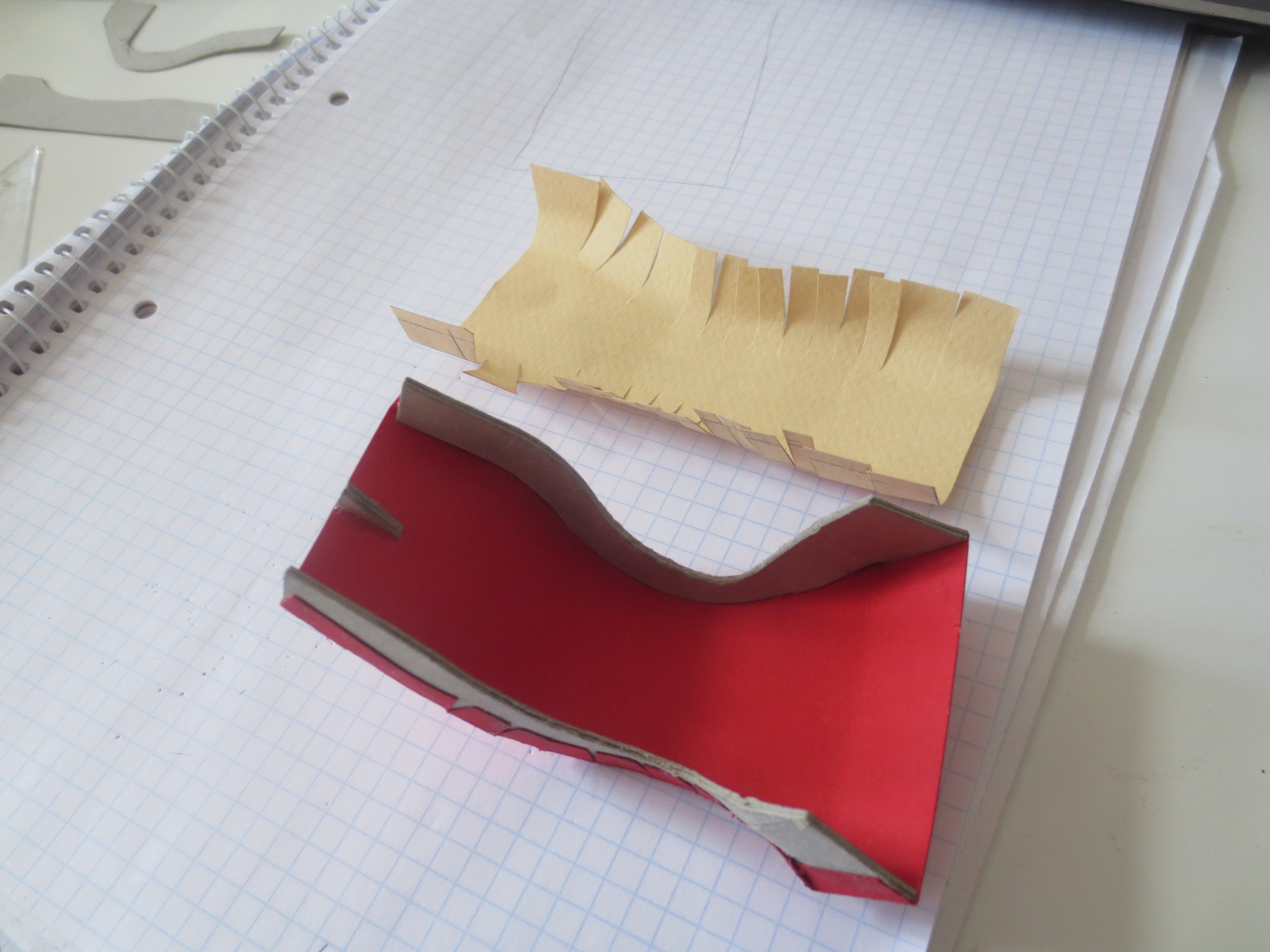
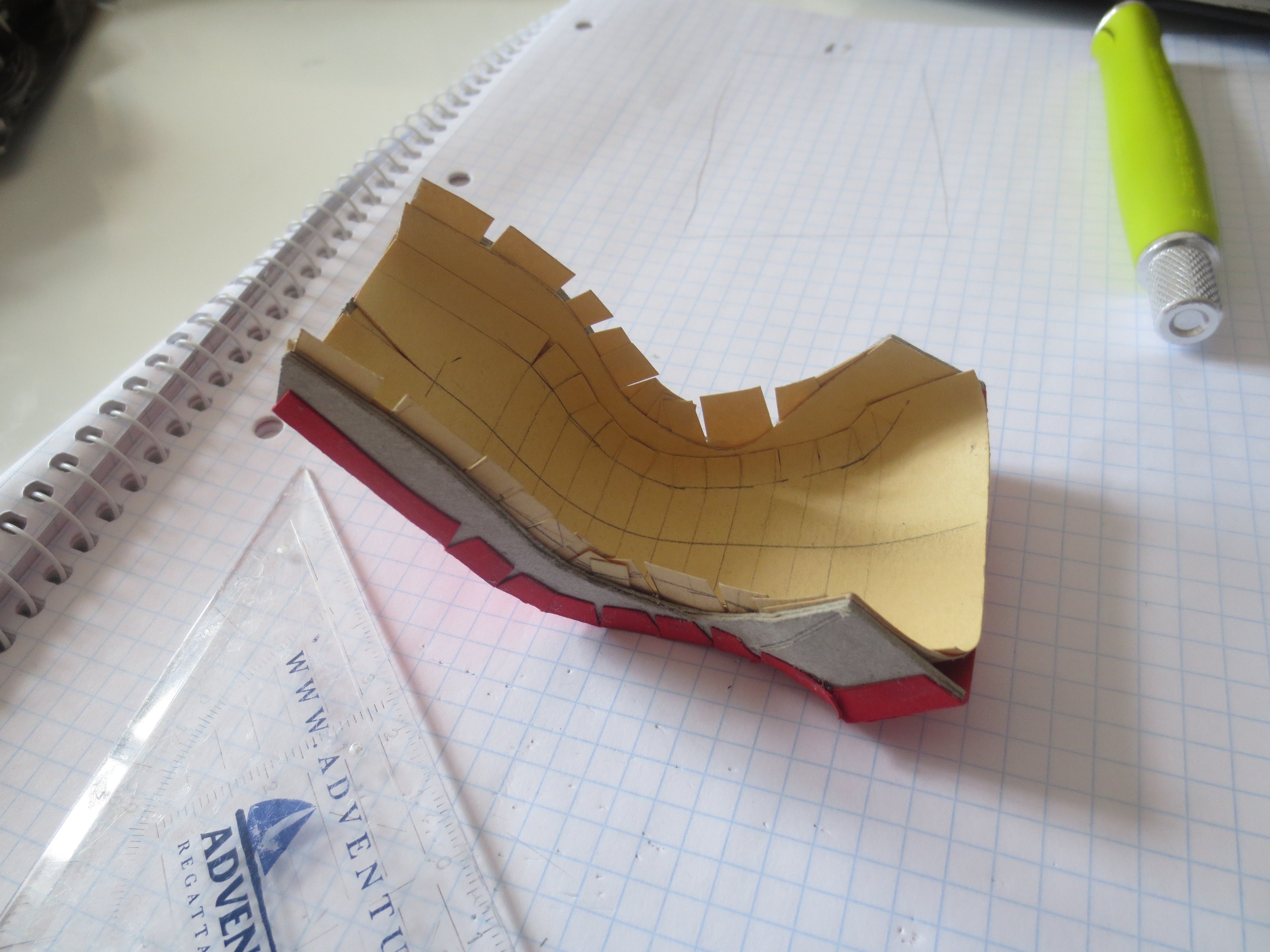
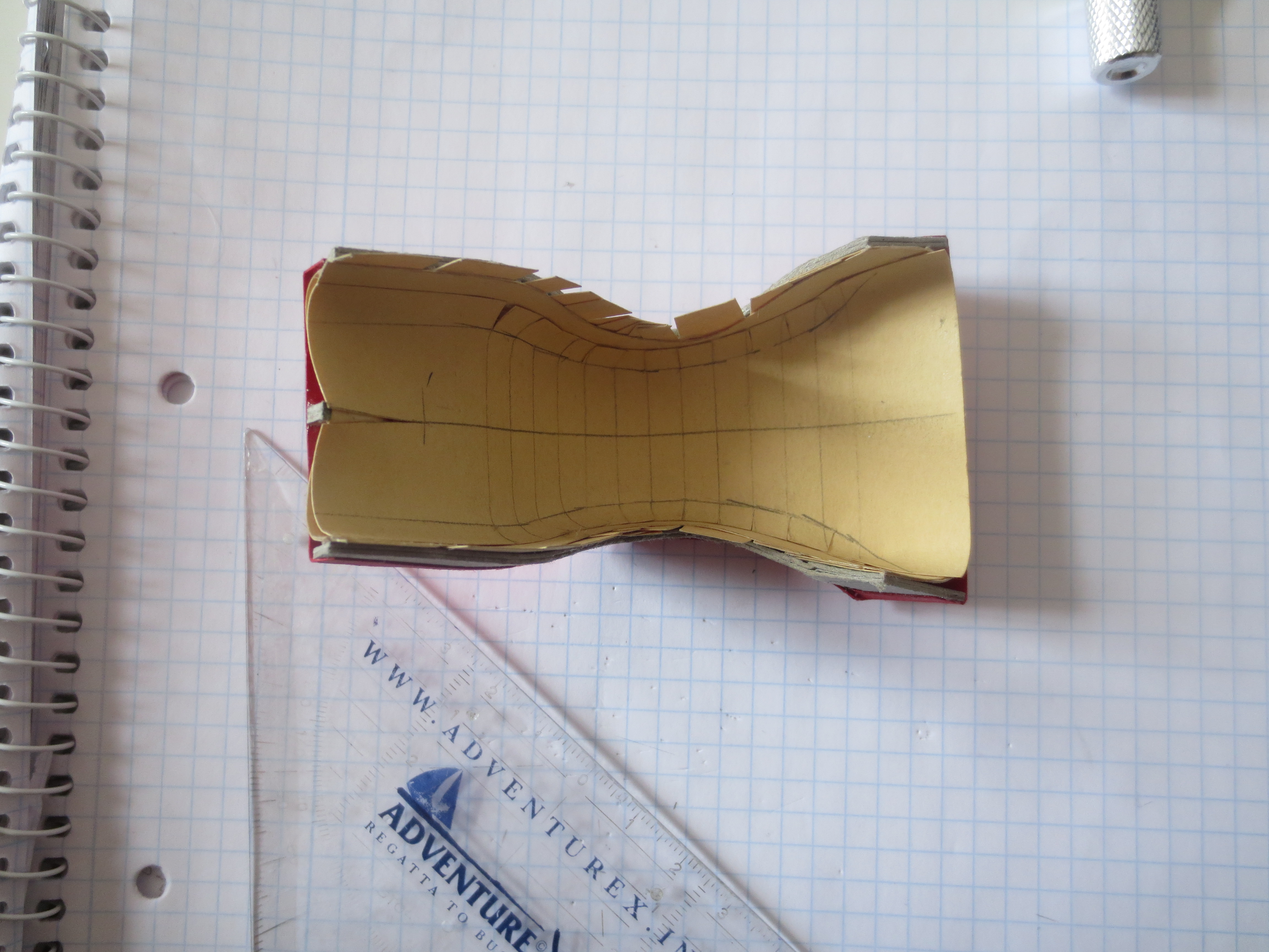
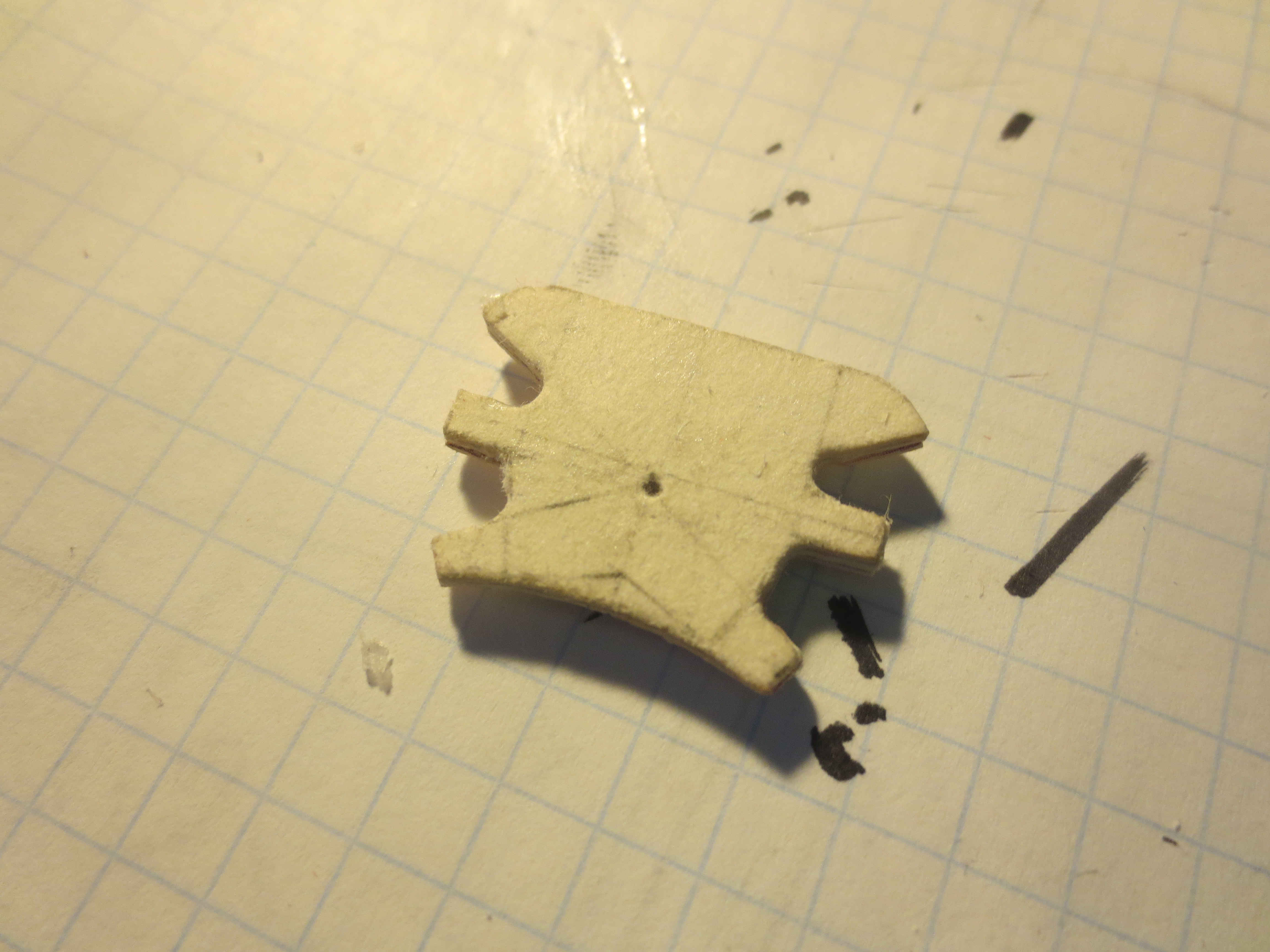
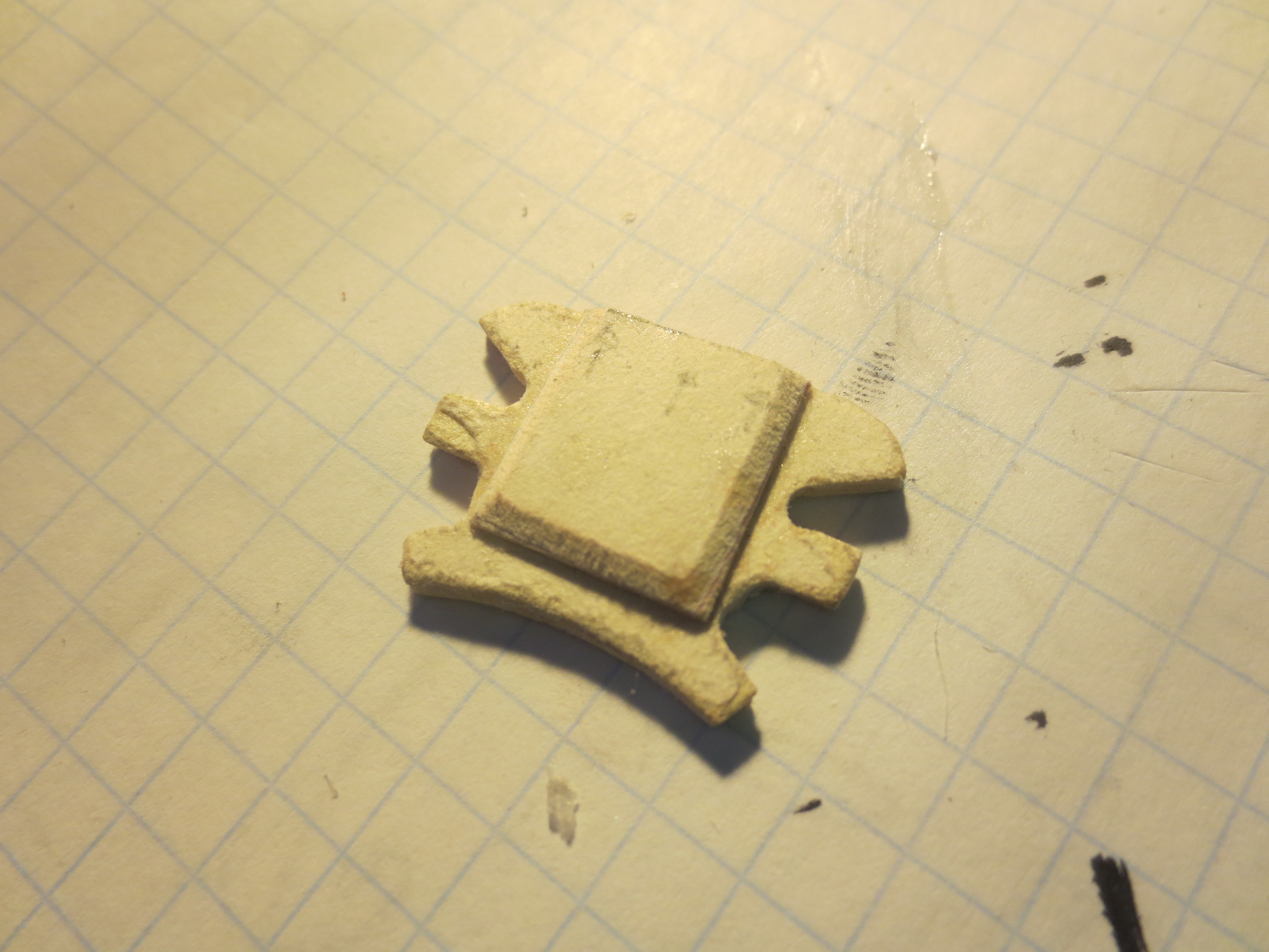
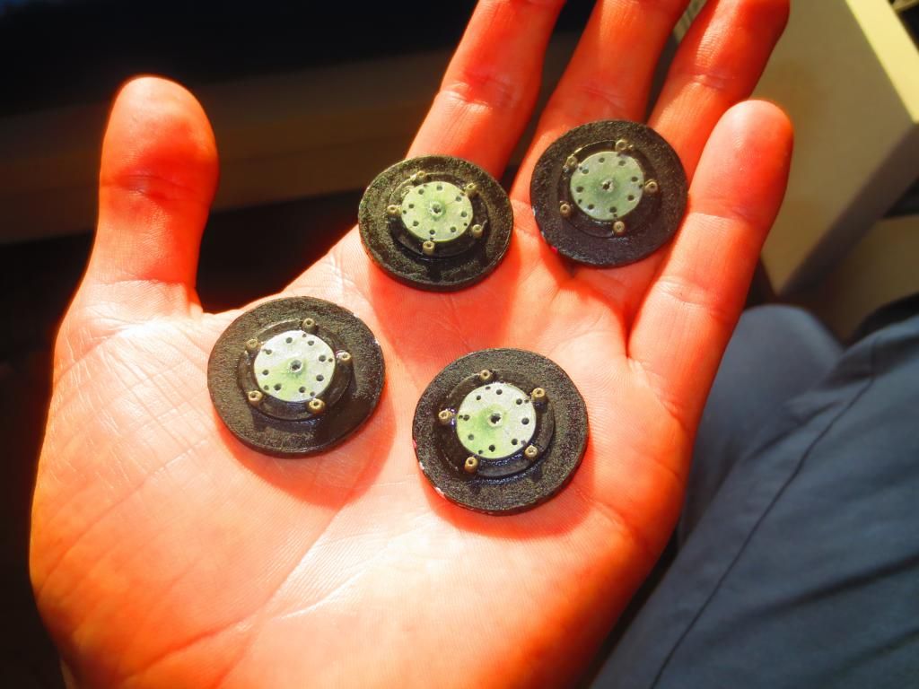
Enough blathered, here are some pics of 448 glued paper snippets:
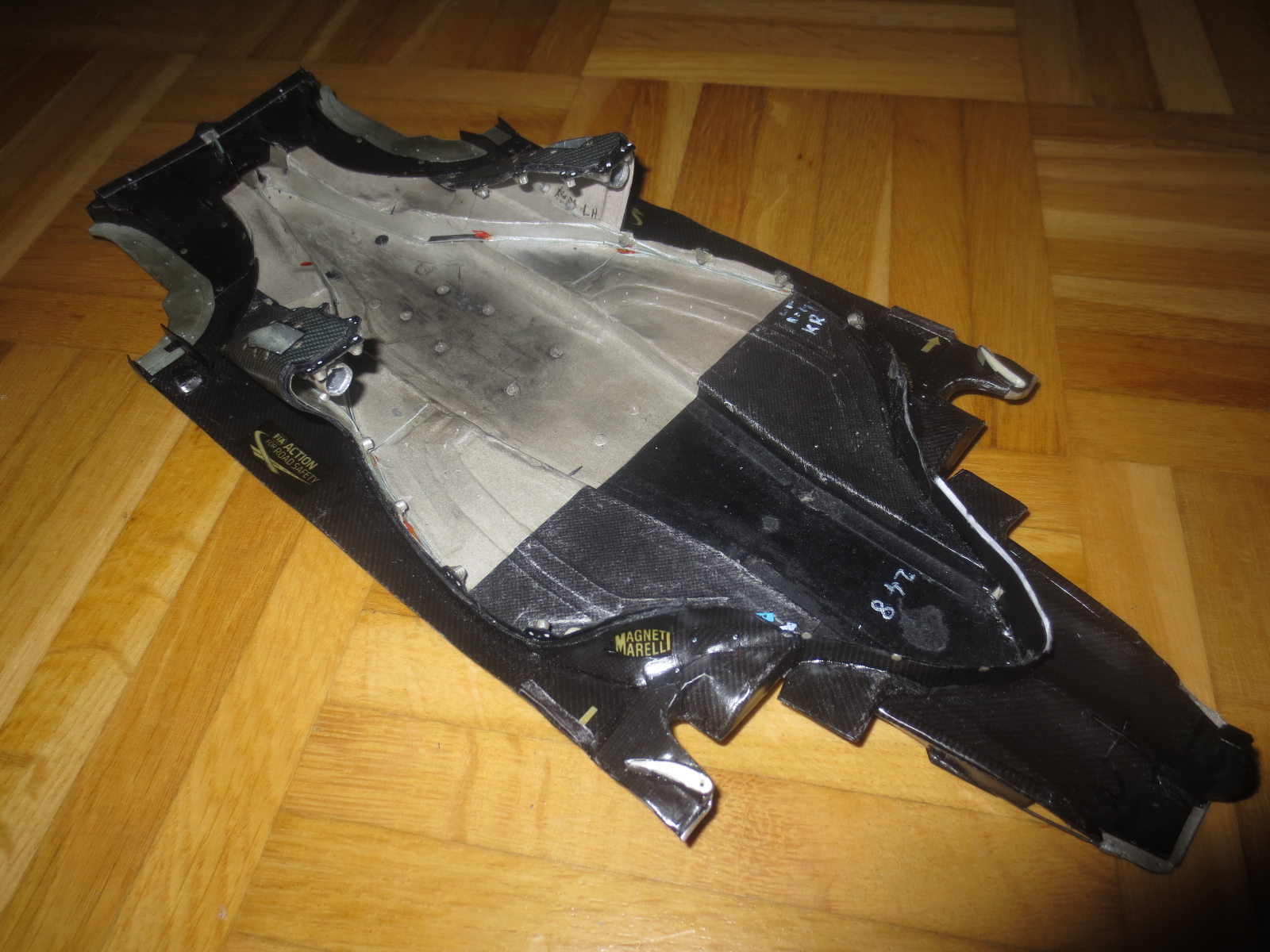
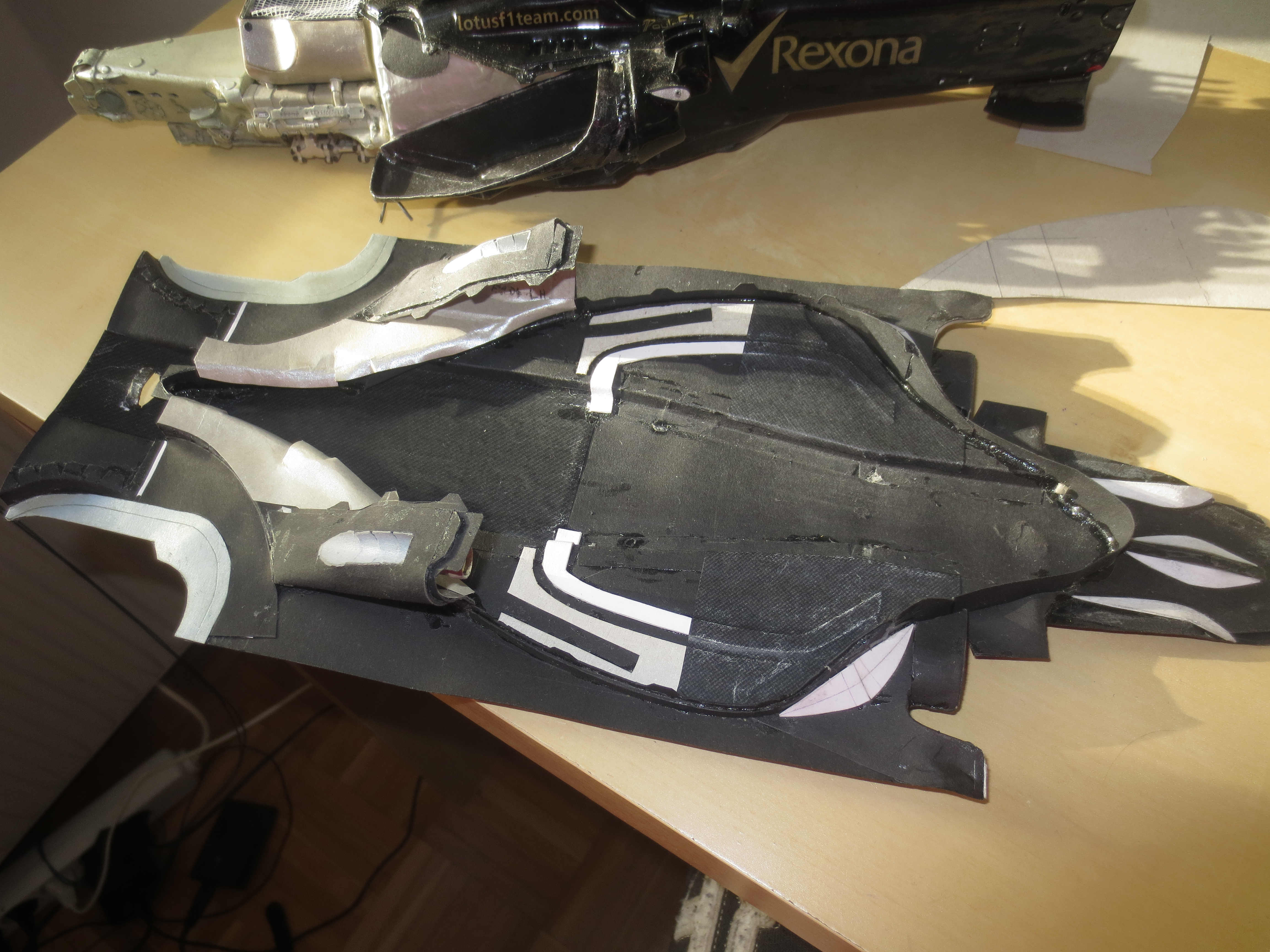
That's the floor structure shortly before getting "carbon fibred". The white stuff you can see is mainly some reinforcement structure. I tried to rebuild the structures as true to the original as possible. Some of the white stuff at the front is also just a 3d radius.
That's my first try with coloured lacquer. To paint the Coanda exhaust grooves with chrome seemed to be a good idea. It looked great as you can see in the next picture. But unfortunately the chrome lacquer and the final clear lacquer aren't good friends...
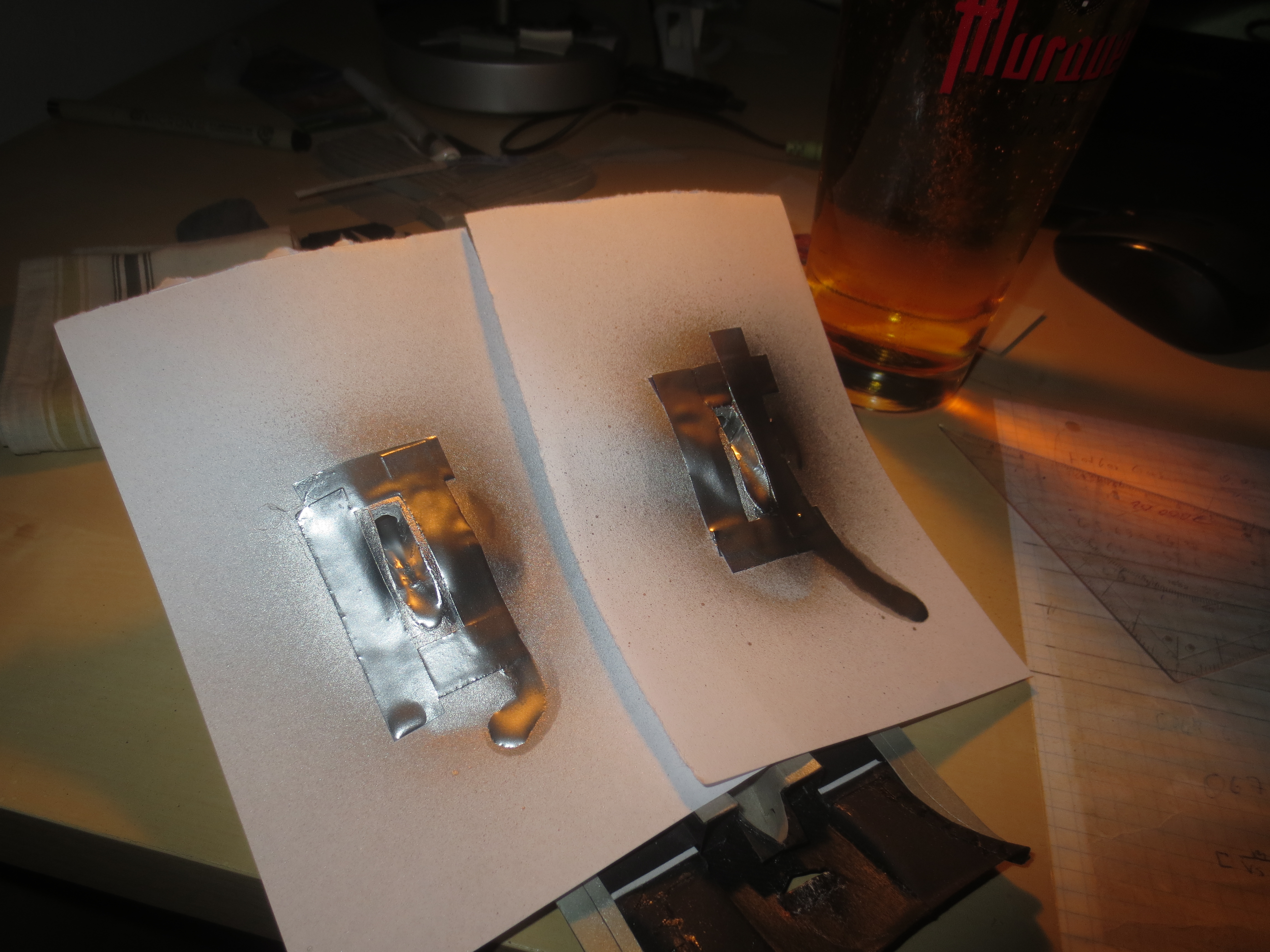
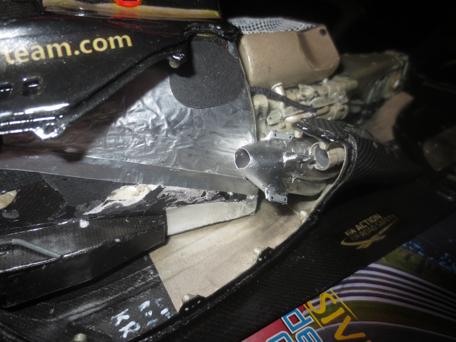
The Coanda exhaust panel after painting. The chrome is pretty soft, so you can see my finger print at the end of the Coanda groove. I did a little bit of a hardness/dryness test.
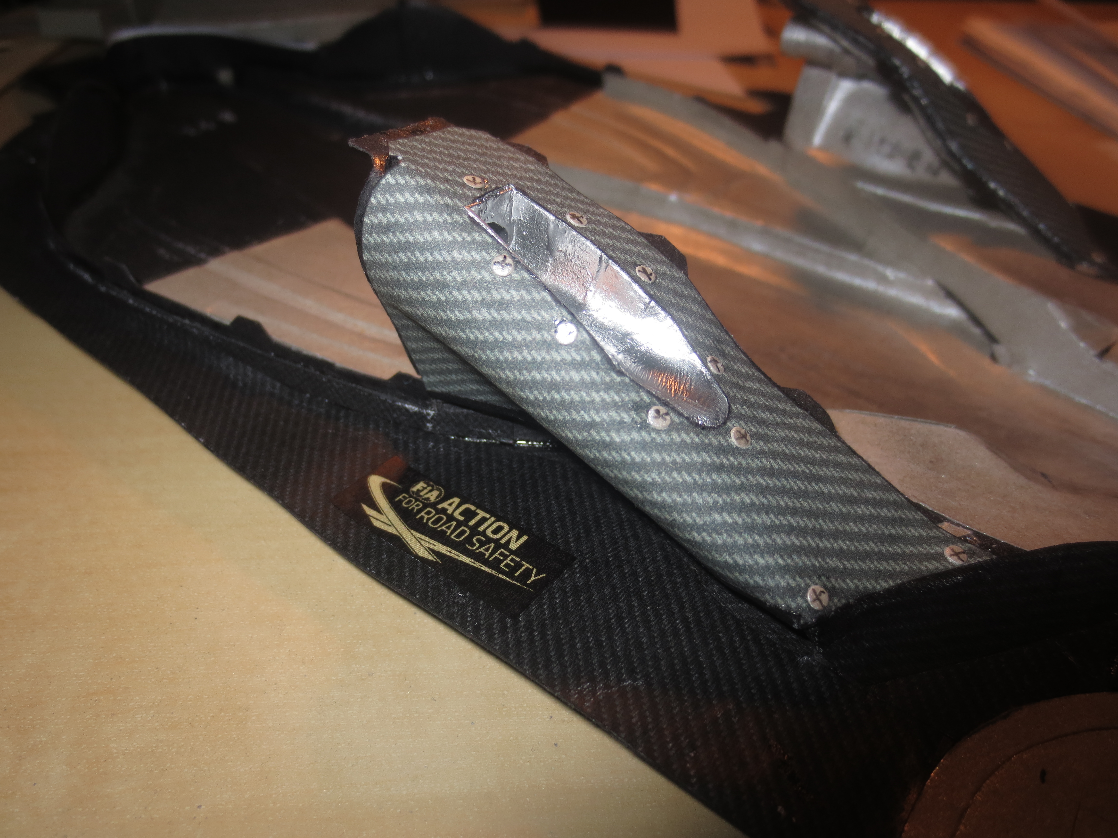
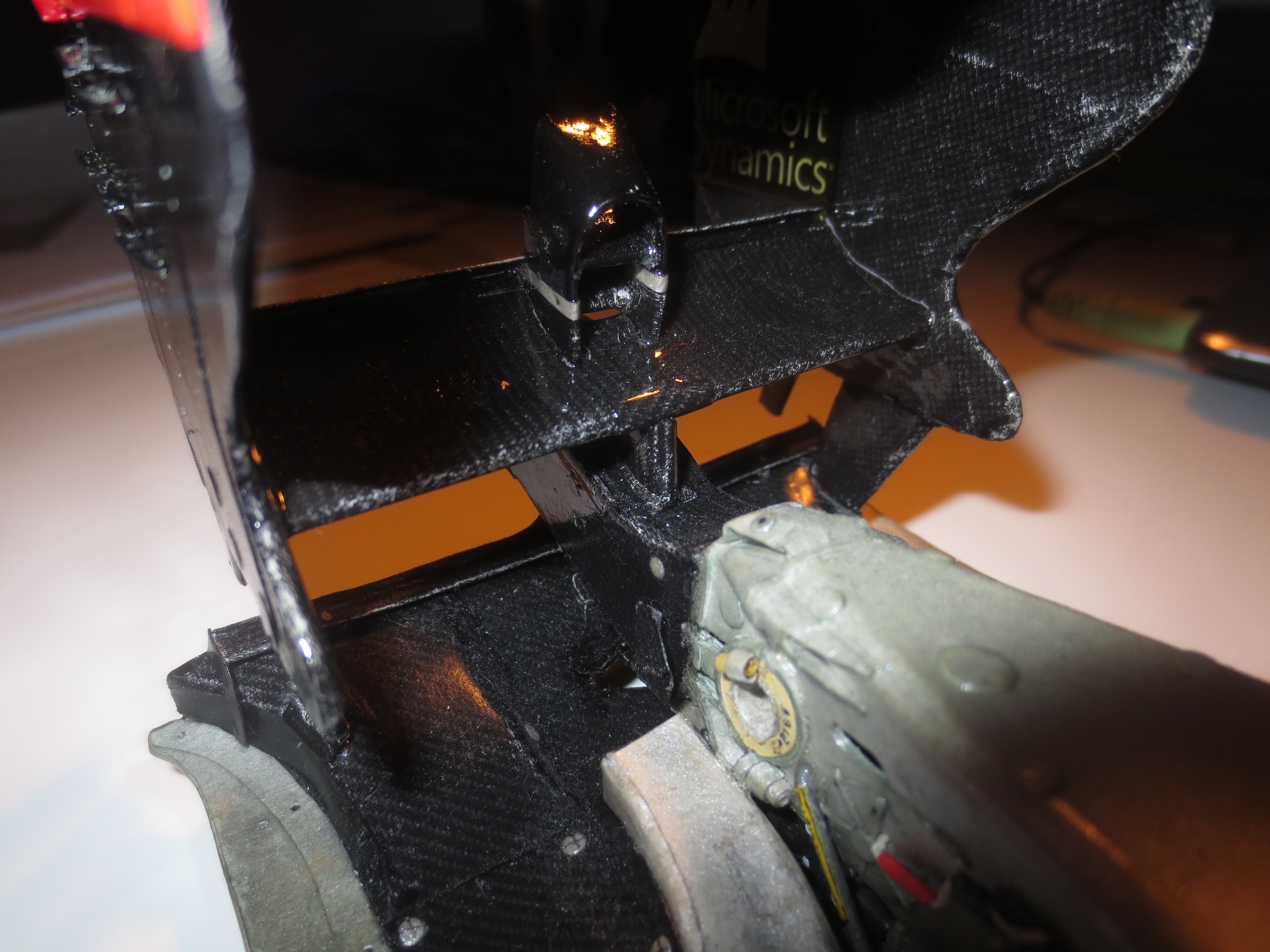
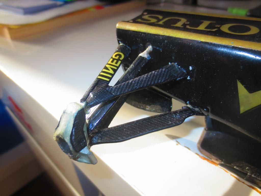
The famous Lotus floor stay. Wonderful shape! Teams racked their brains to find out, why the Lotus stay was shaped like this. It stayed just for the 2013 season in this configuration.
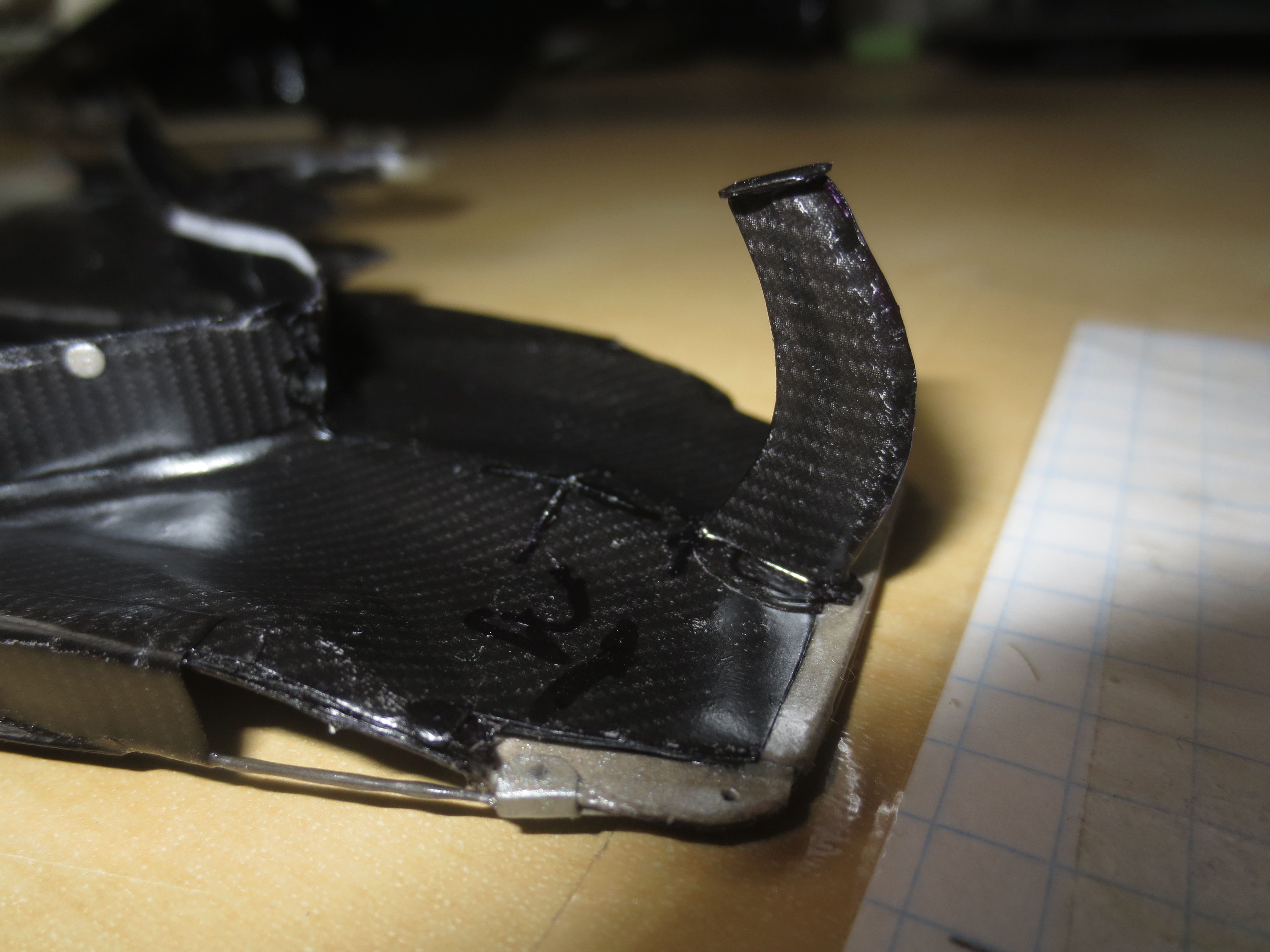
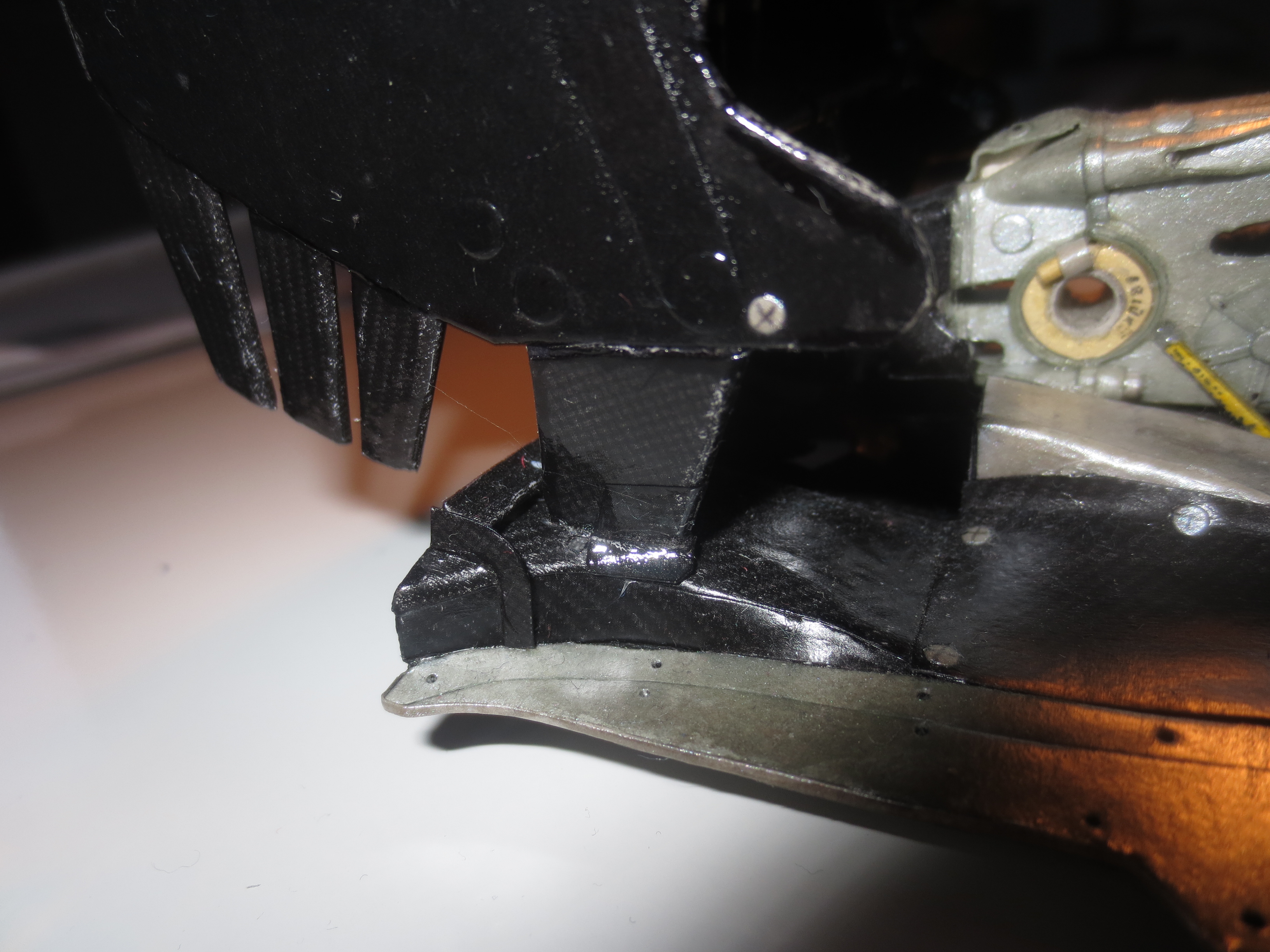
The floor front corner with its weird shape. The strange bulge coming from the inside of the car houses the lower crash elements.
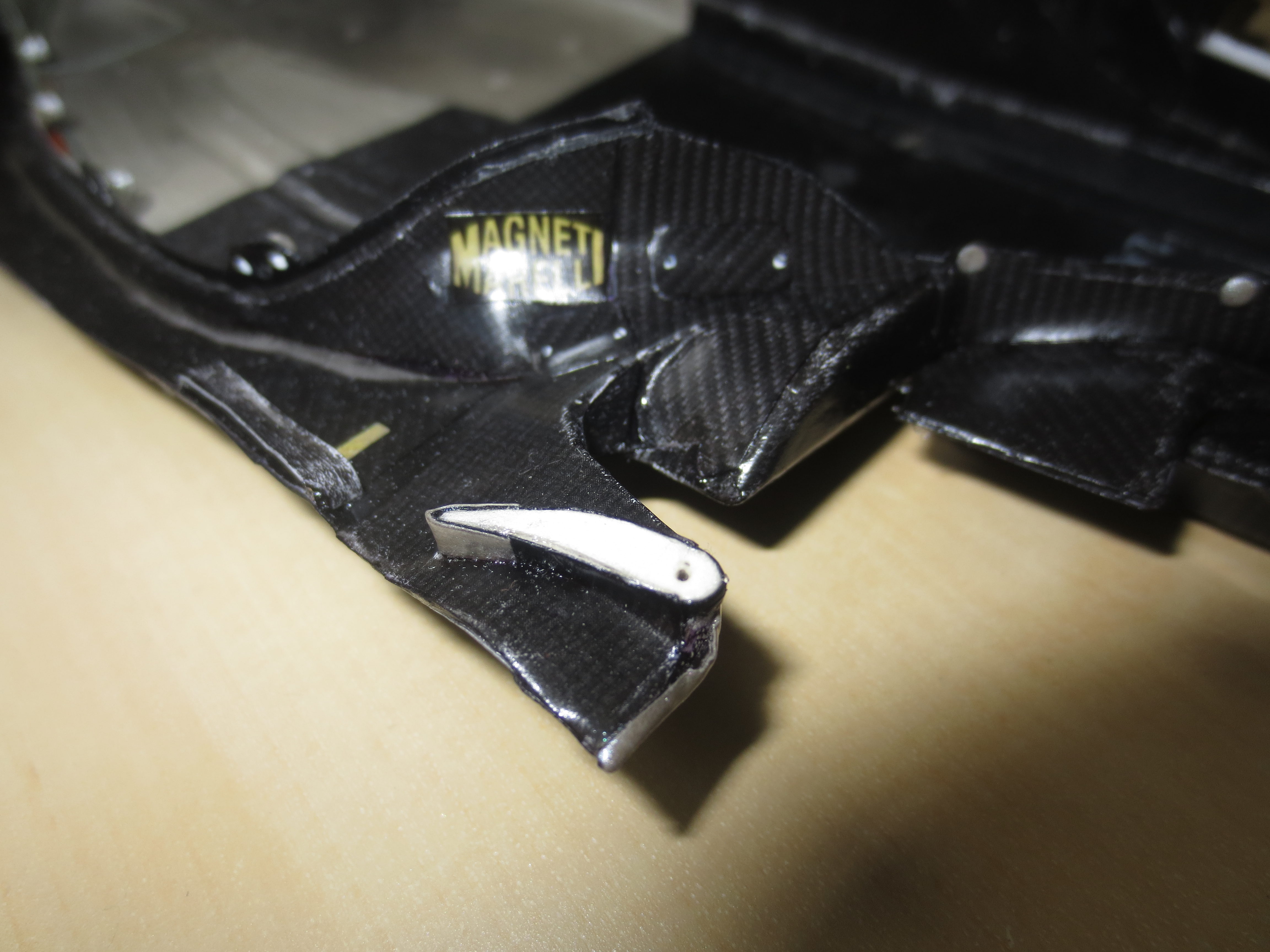
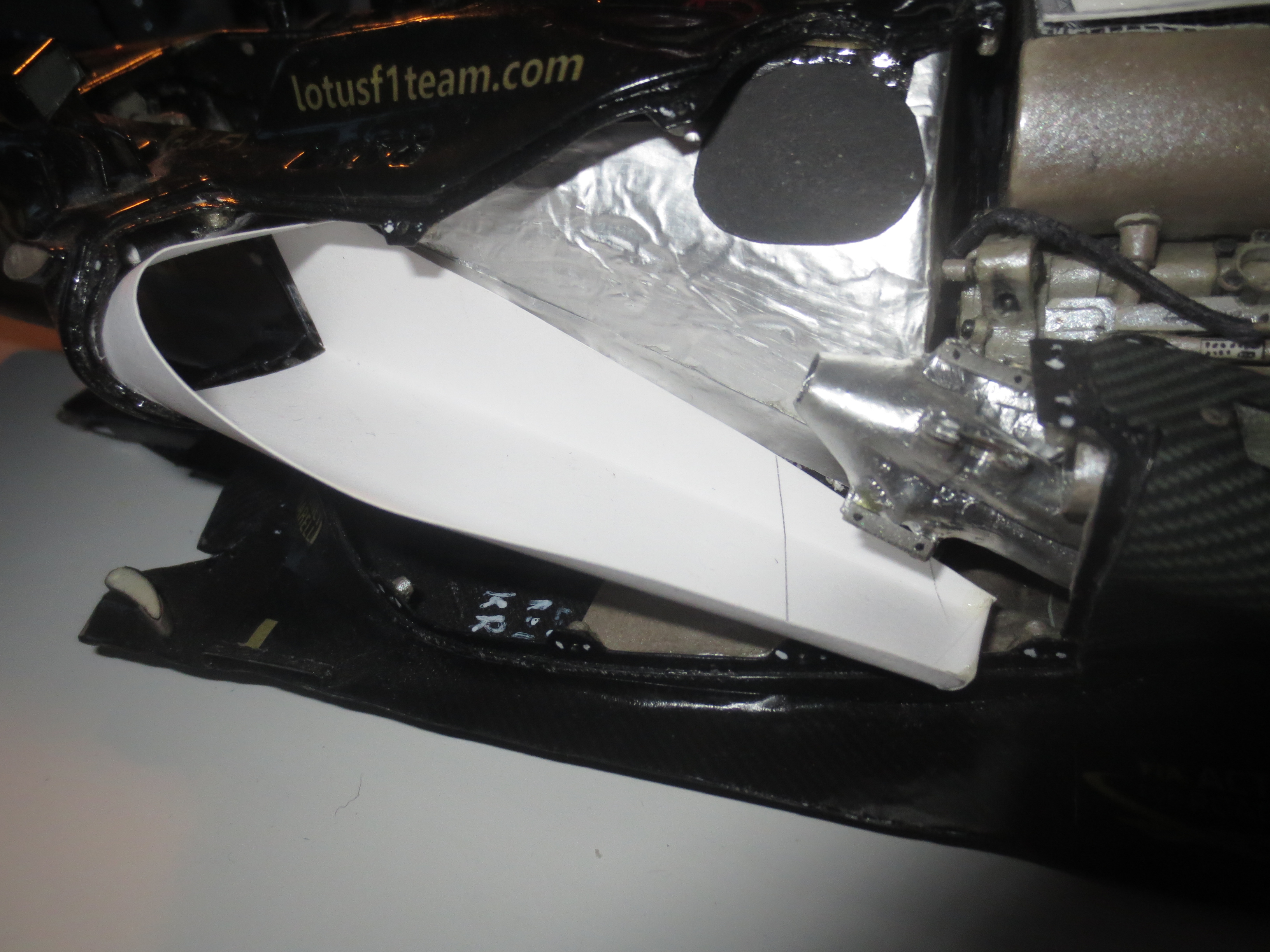
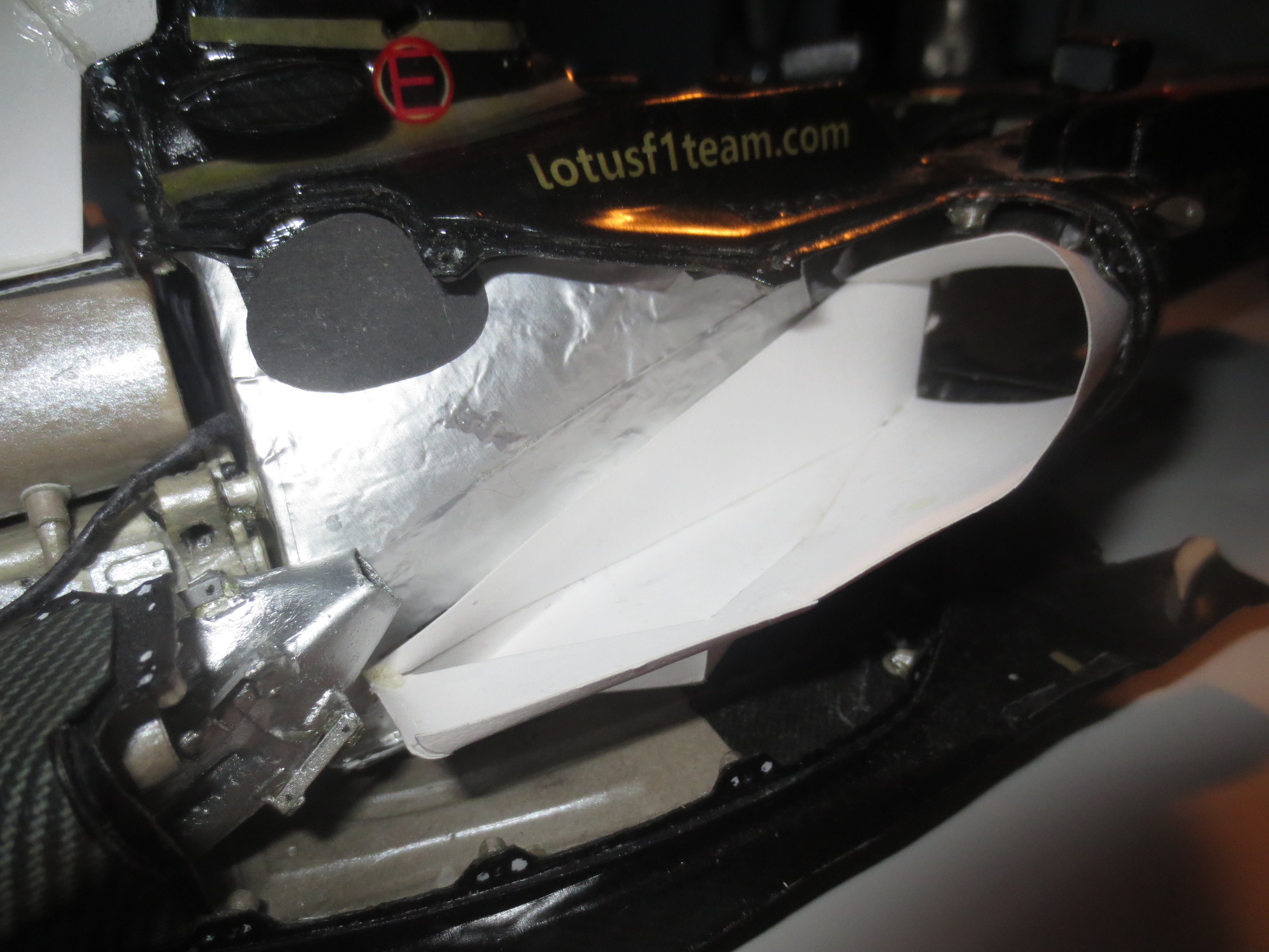
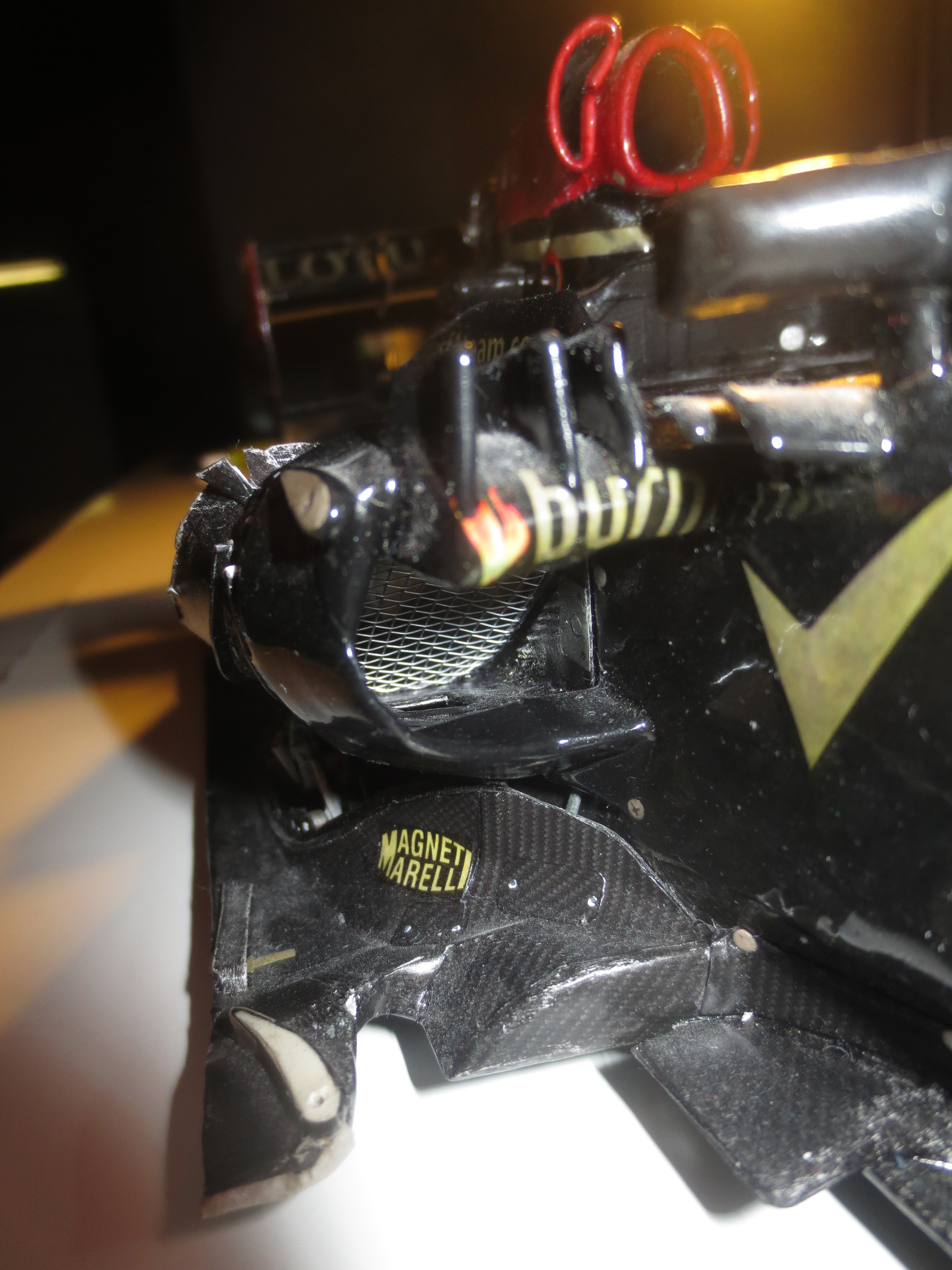
The blown starter hole air intake below the Coanda exhaust. Red Bull introduced this idea already in 2012. Lotus and Caterham followed in 2013.
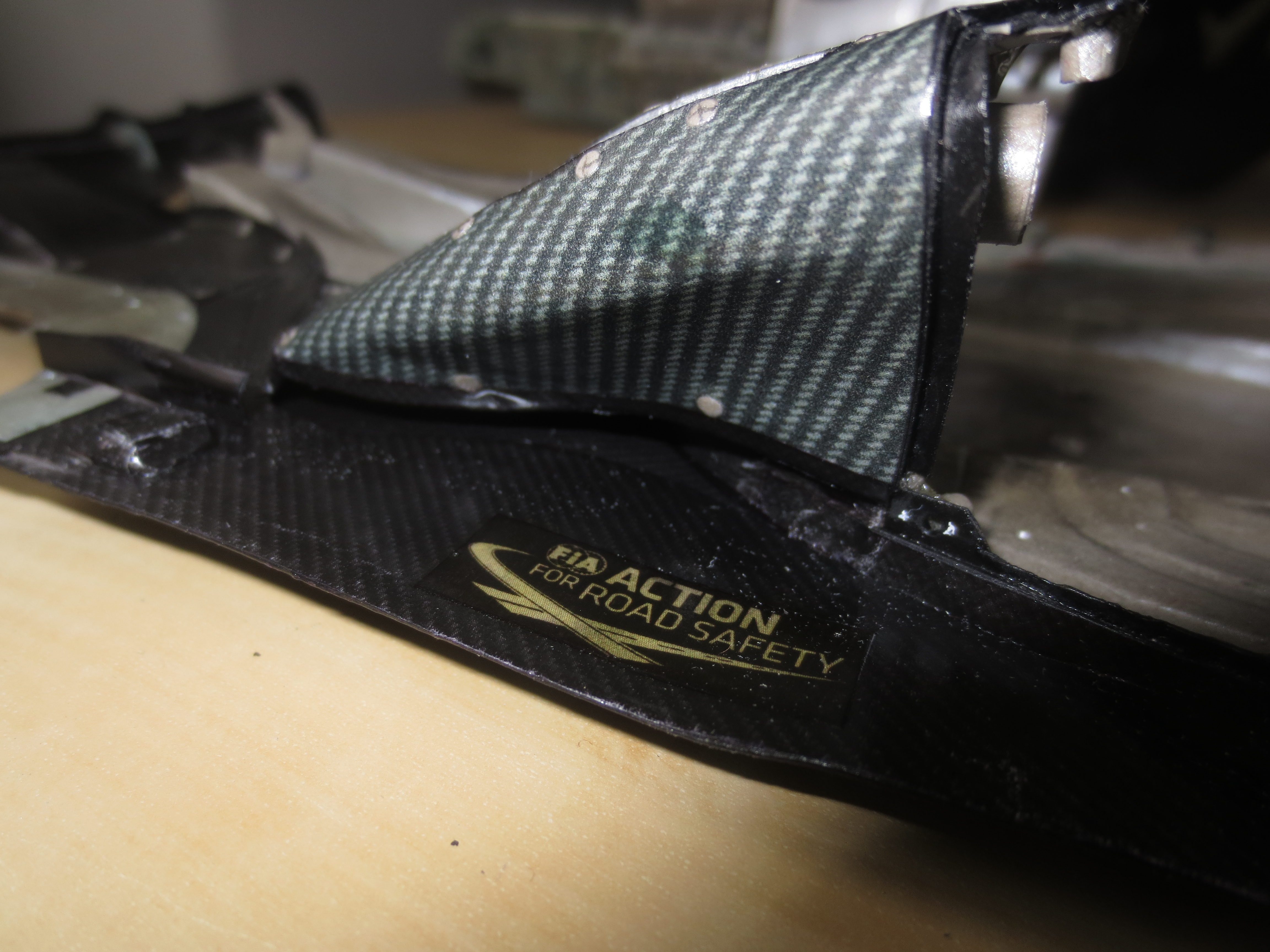
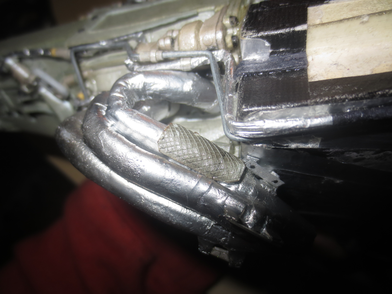
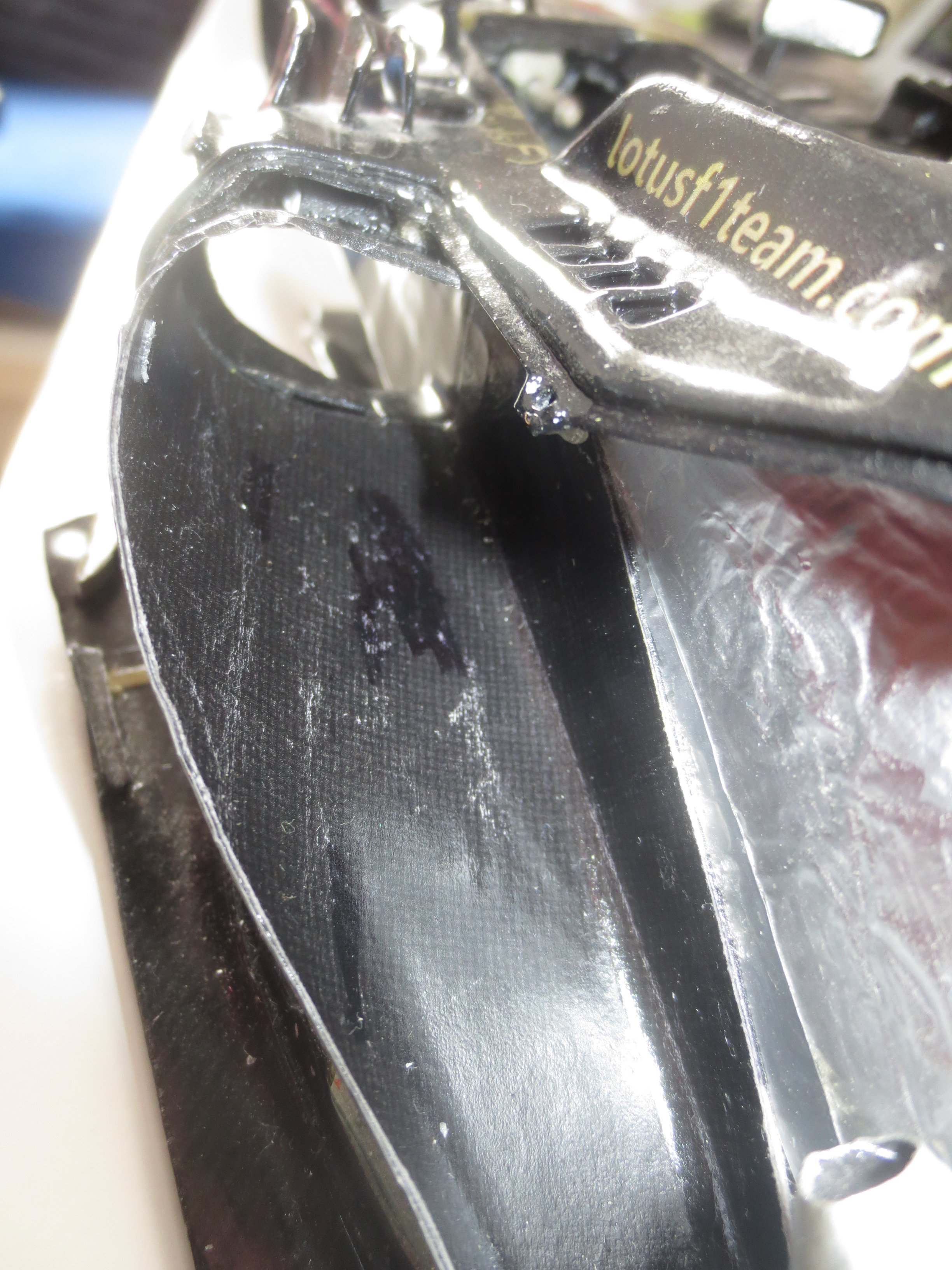
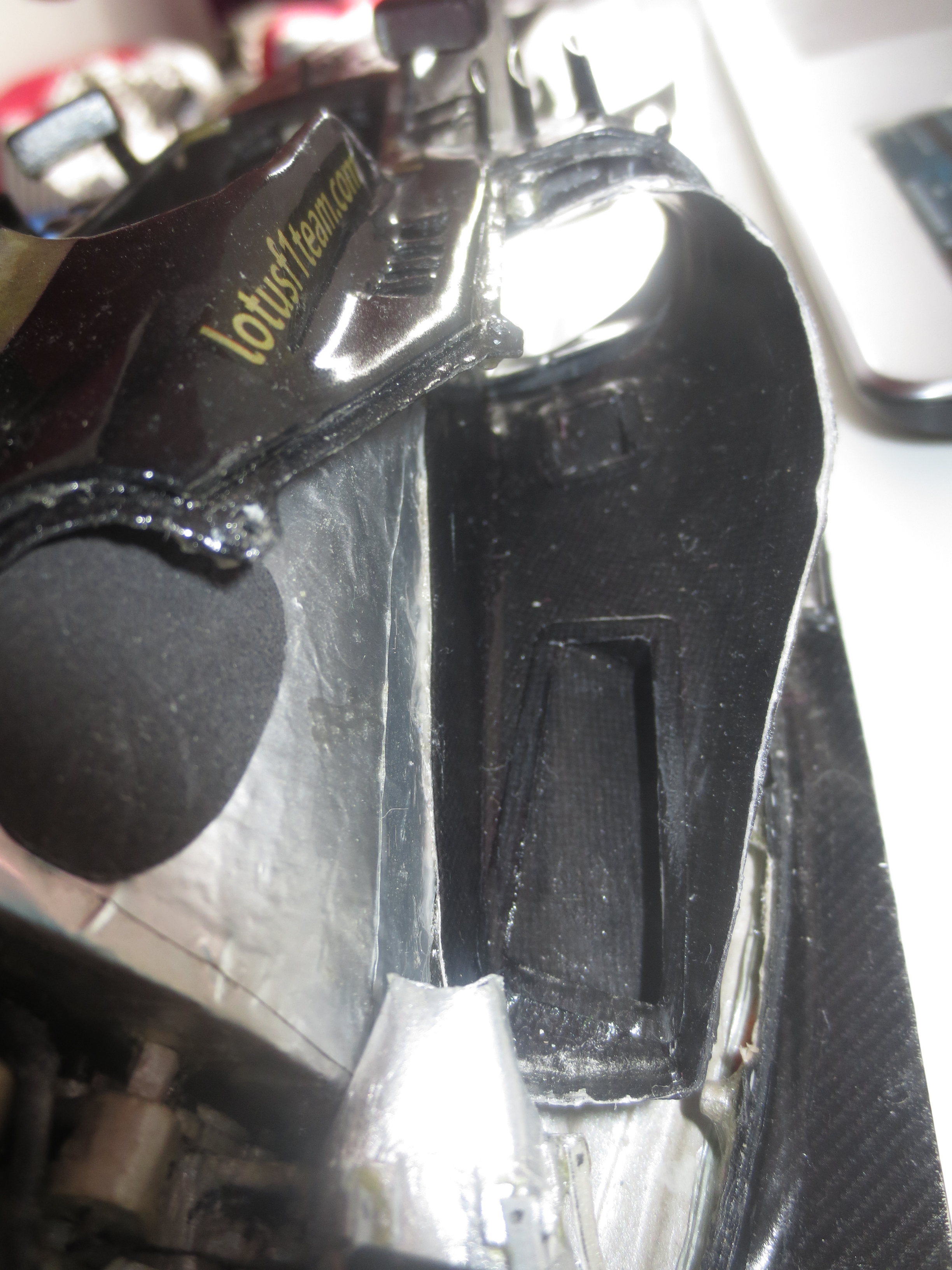
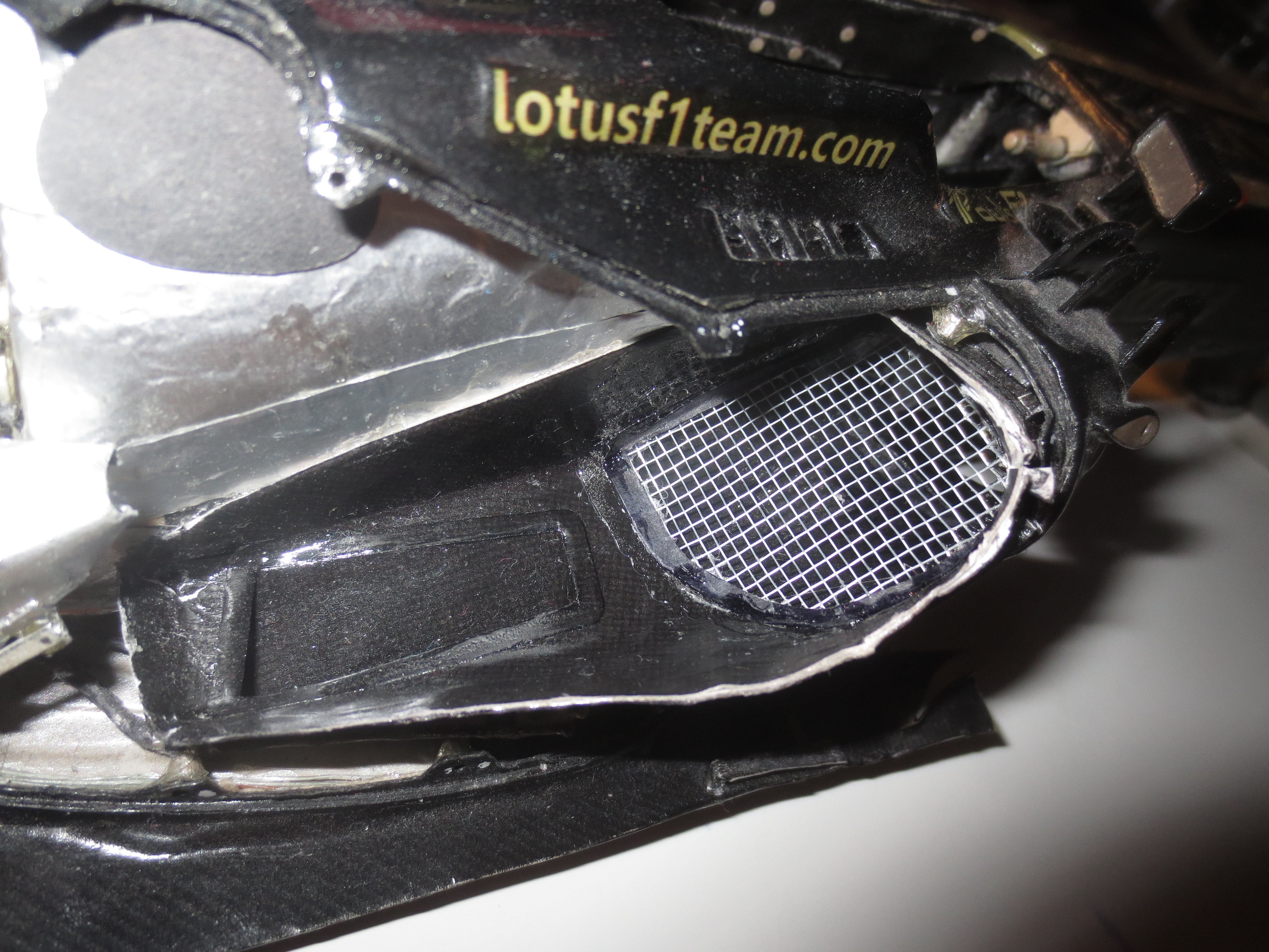
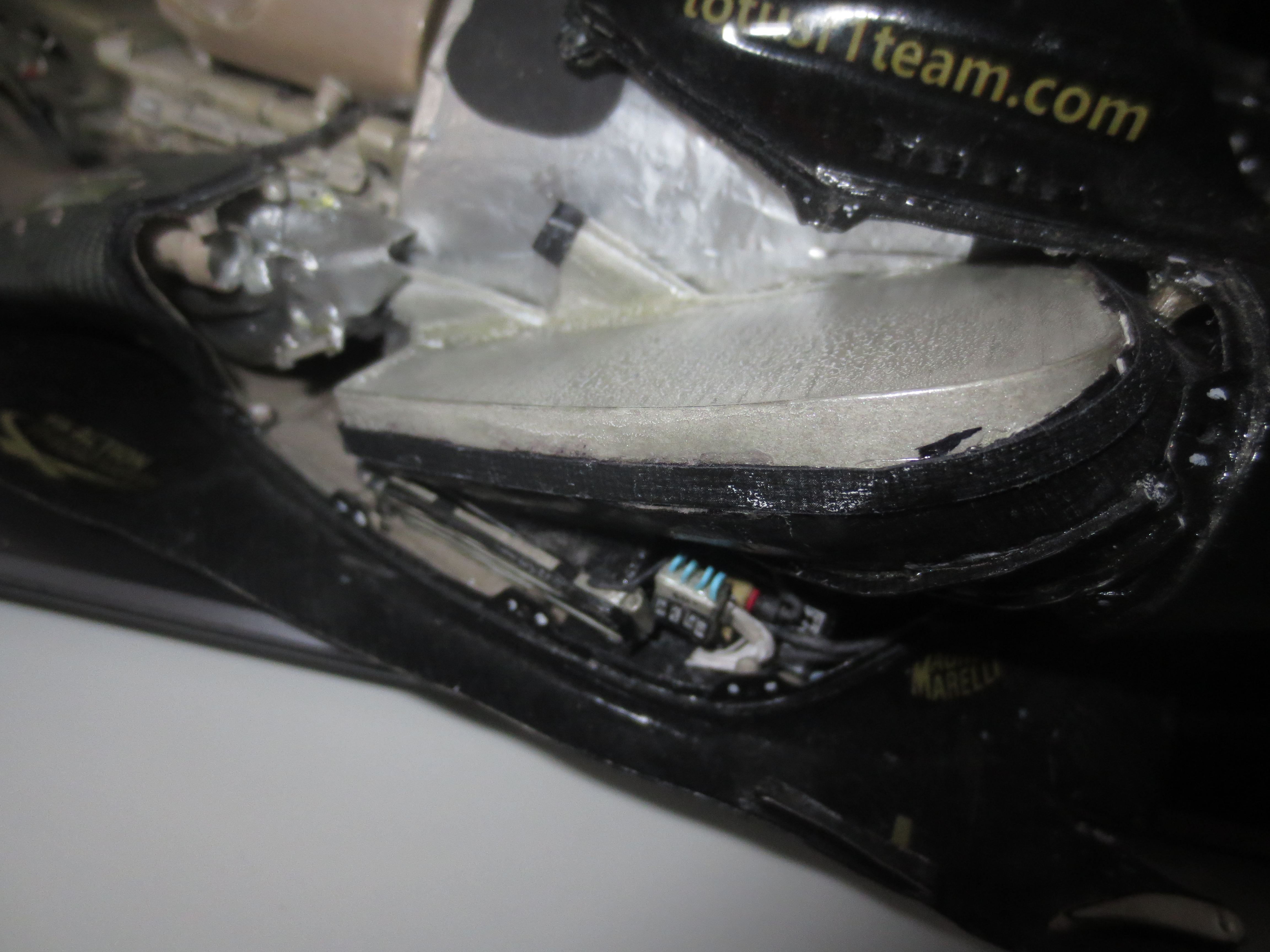
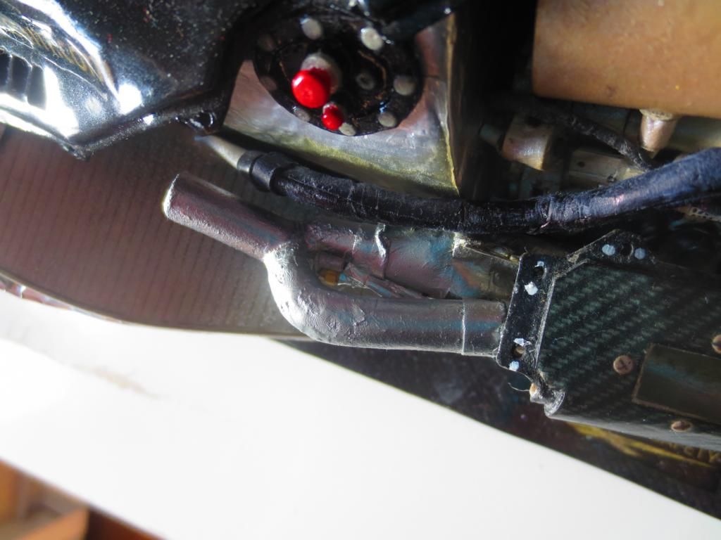
The Coanda exhaust panel from the inside. Not very spectacular, but you can see the port for the exhaust manifold, the whole heat shielding and some live locks (i.e. kind of bolts) to fix the surrounding bodywork.
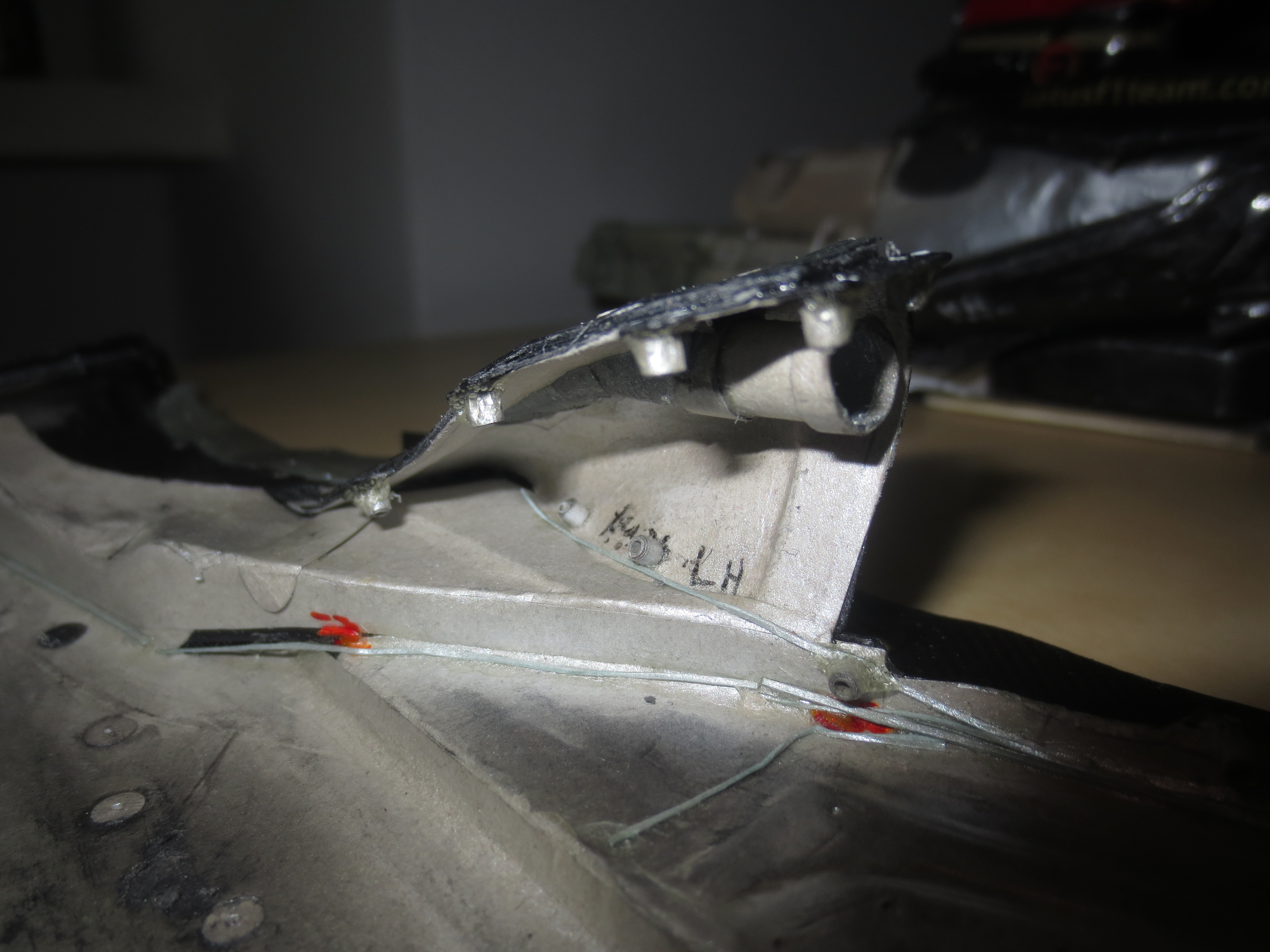
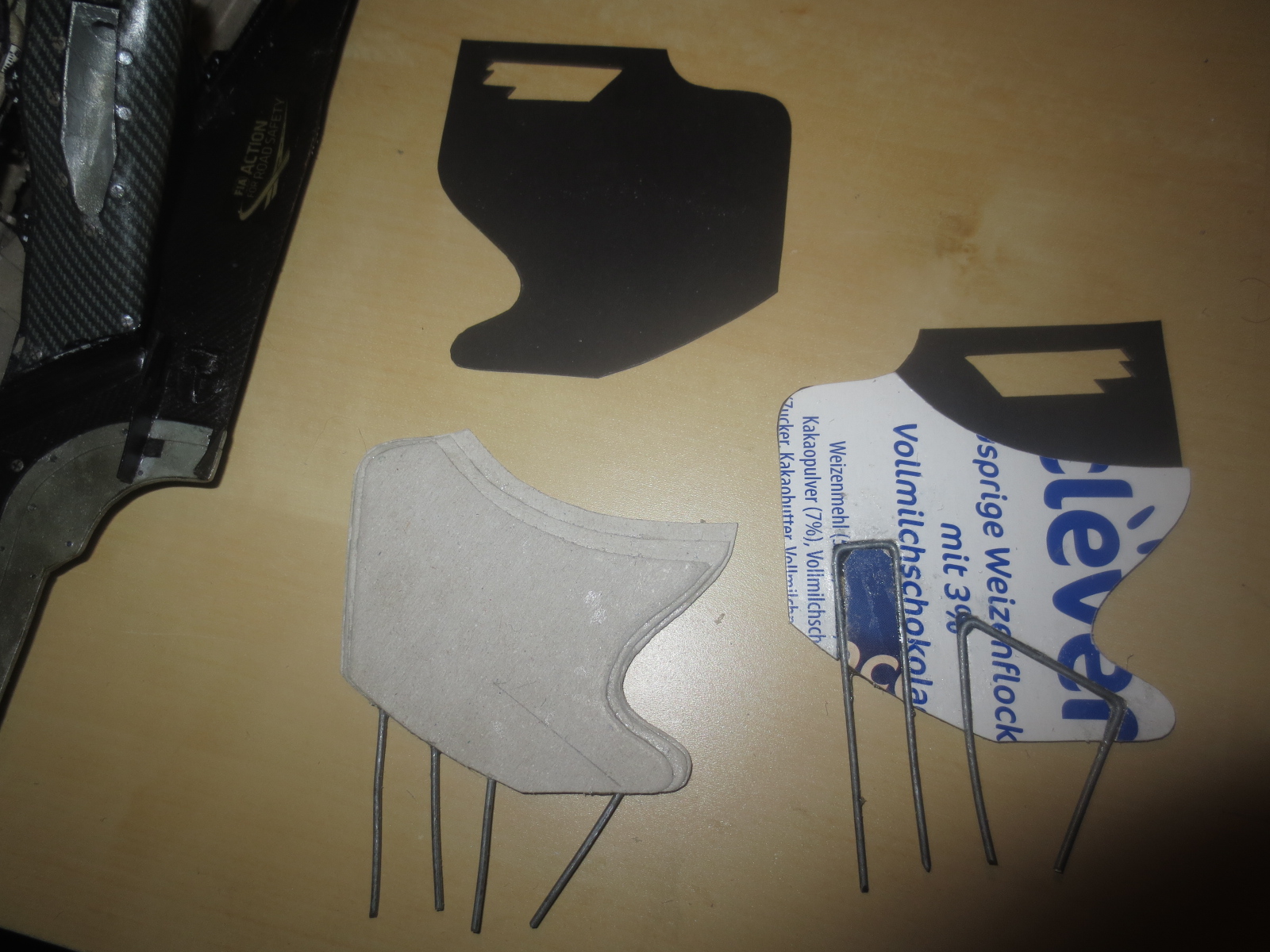
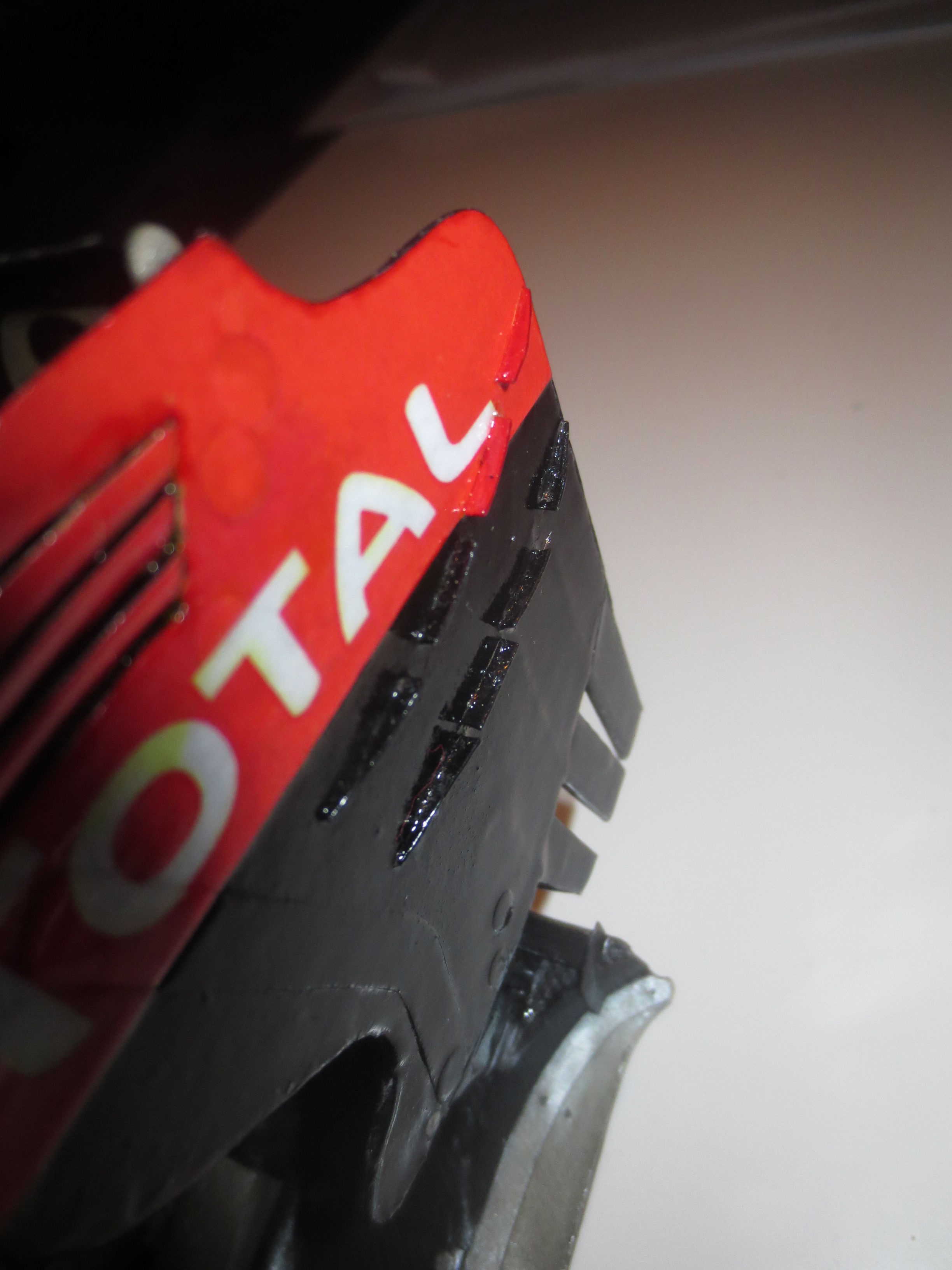
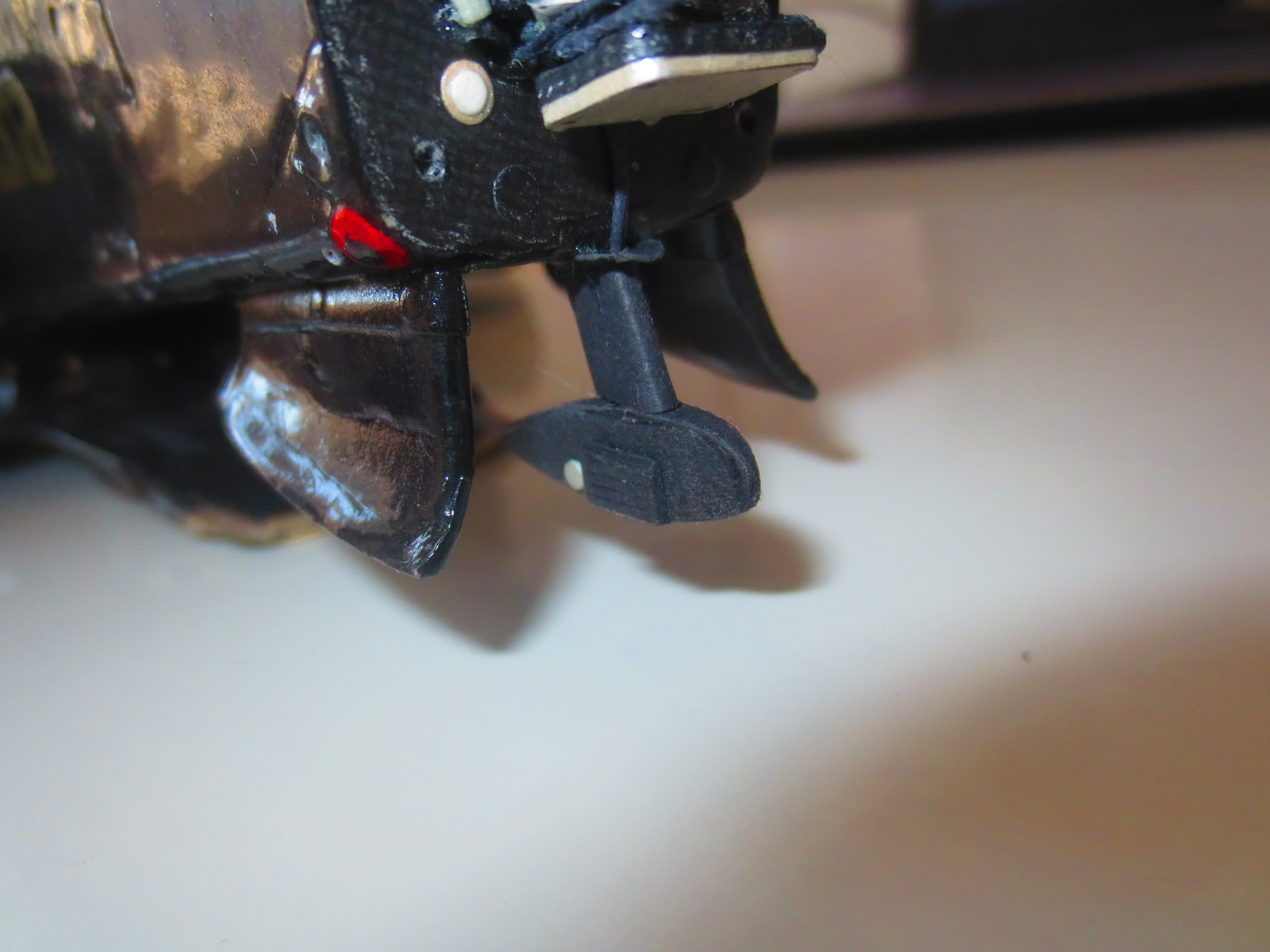
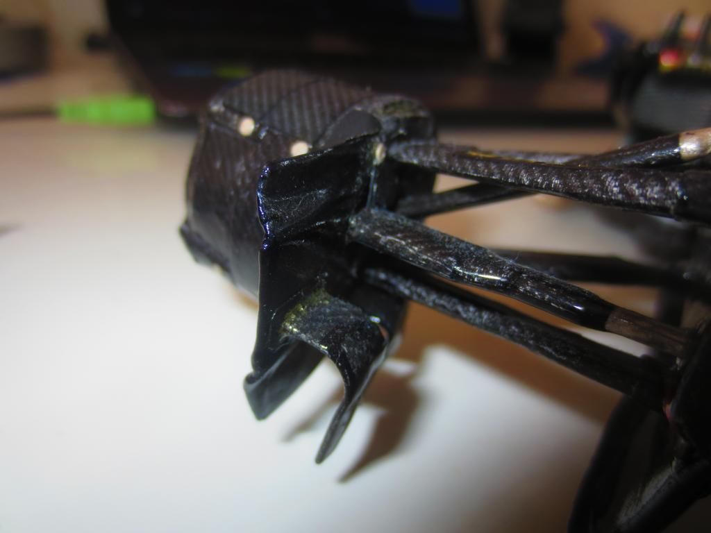
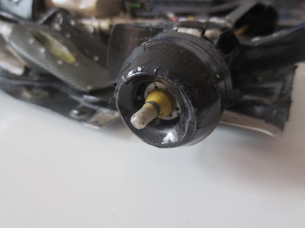
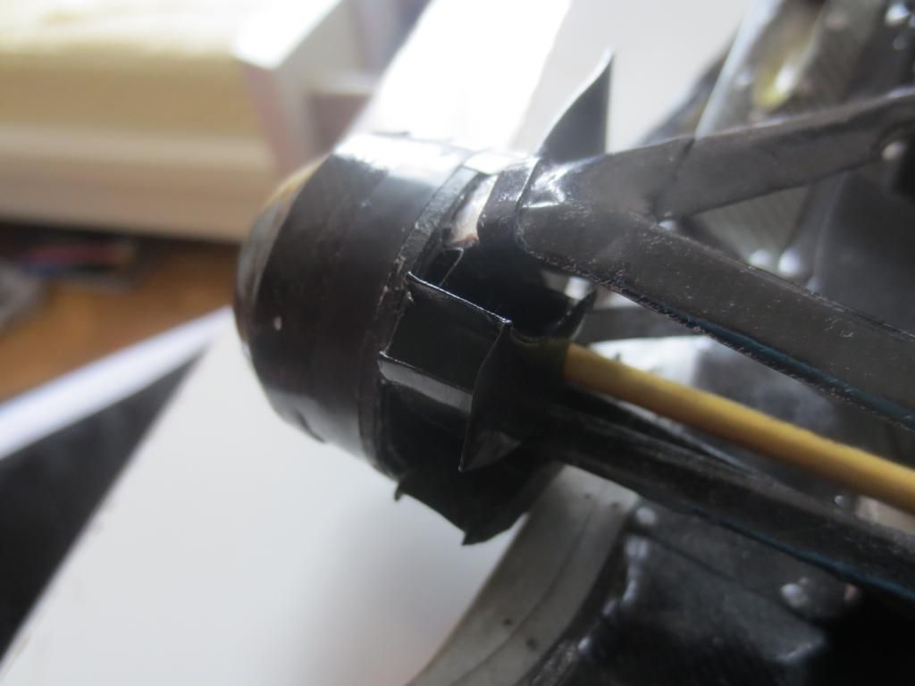
The tyre vanes which help to lead the exhaust plume towards the gap between the tyres and the floor. You can also see the IR sensor housing (outside of the main tyre vane) which looks at the rear tyre to log their temperature development.
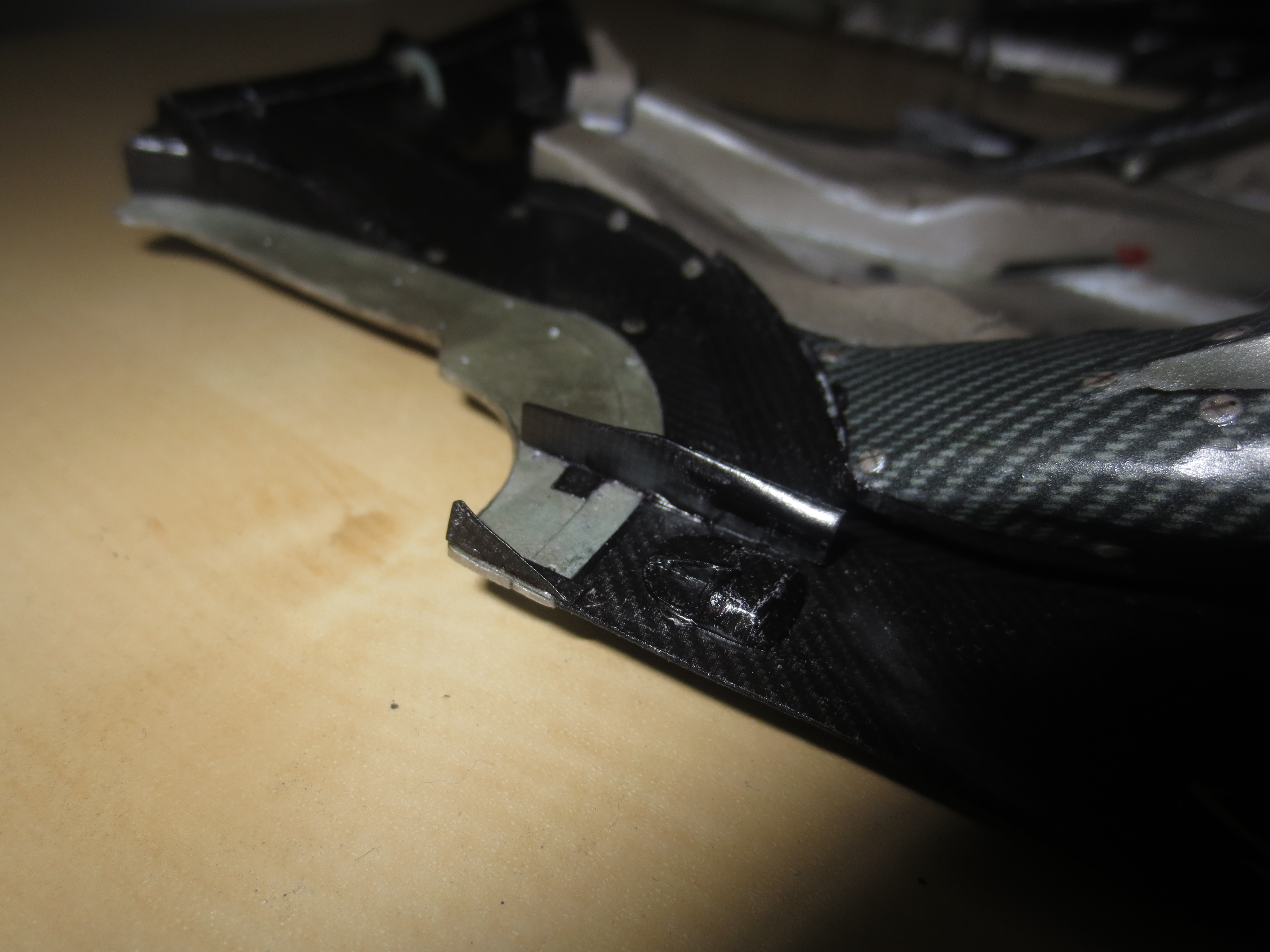
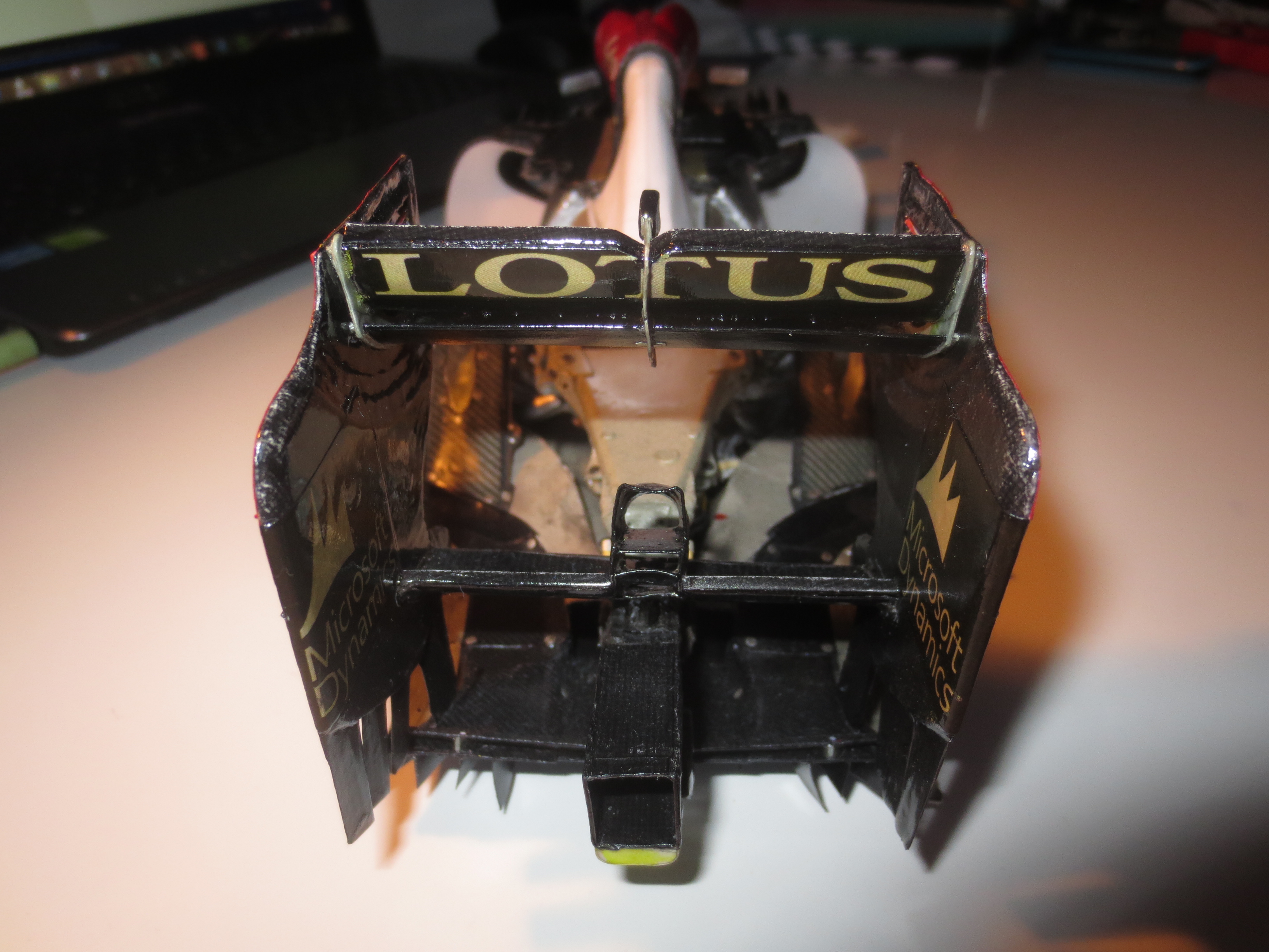
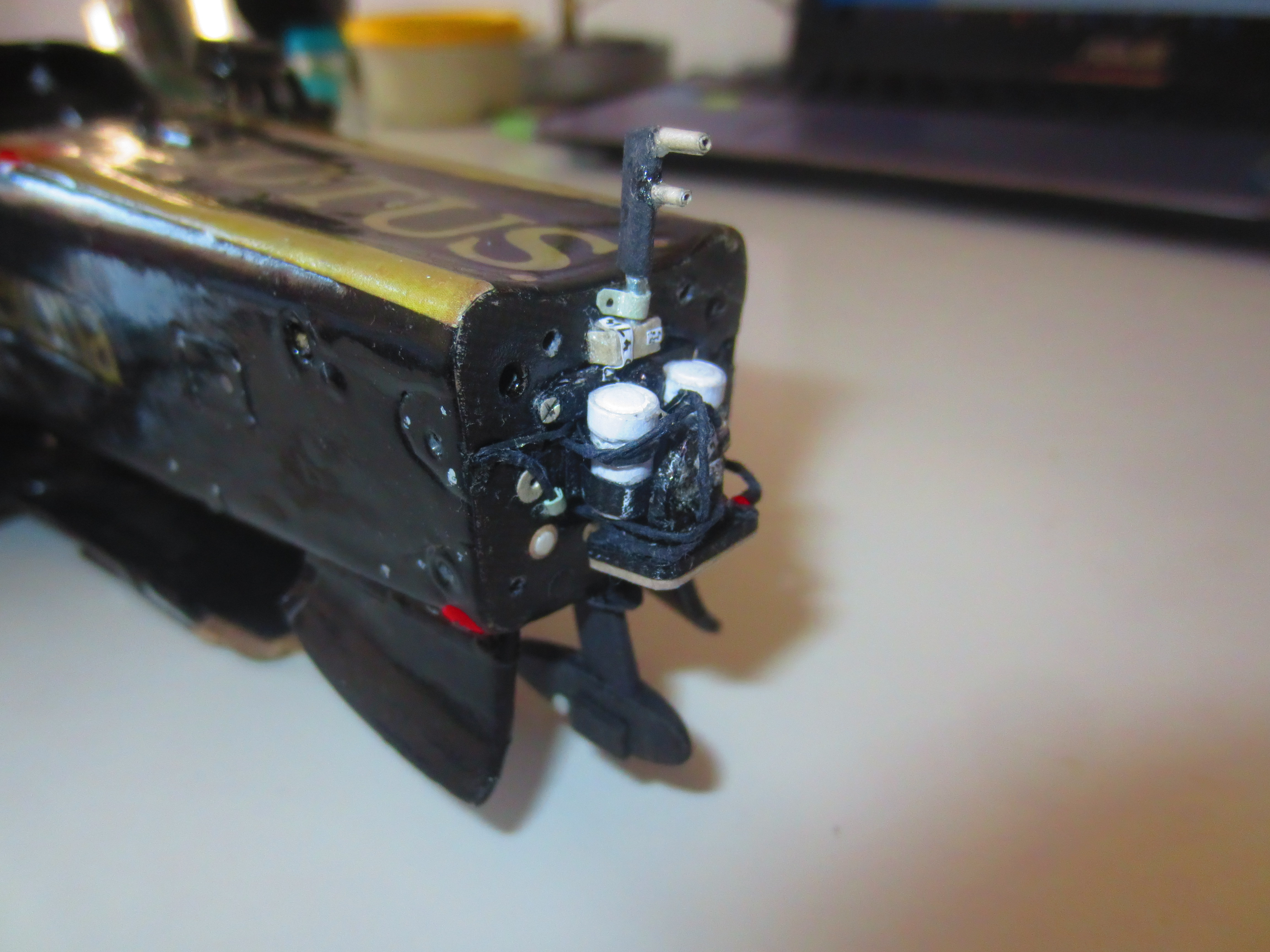
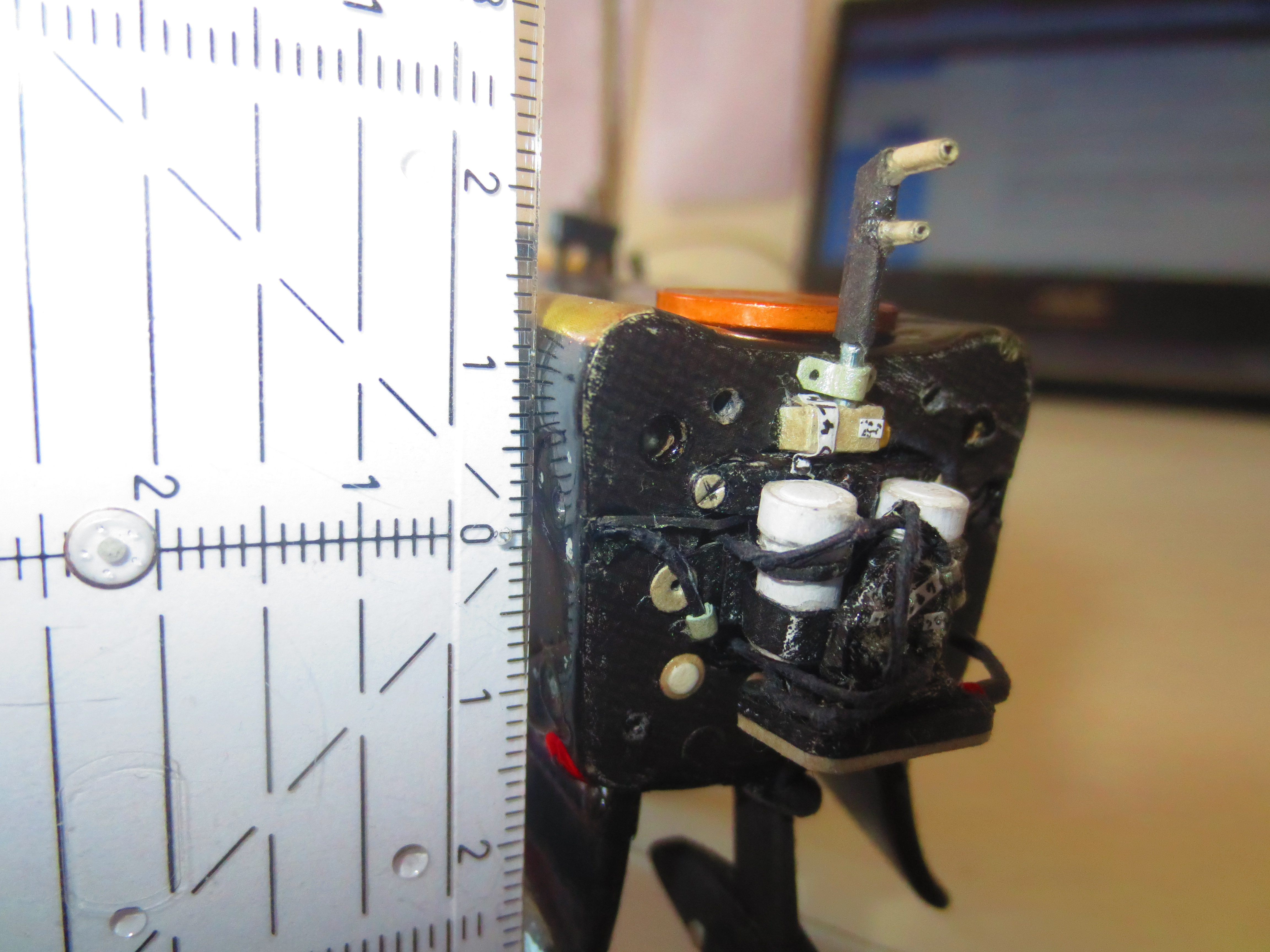
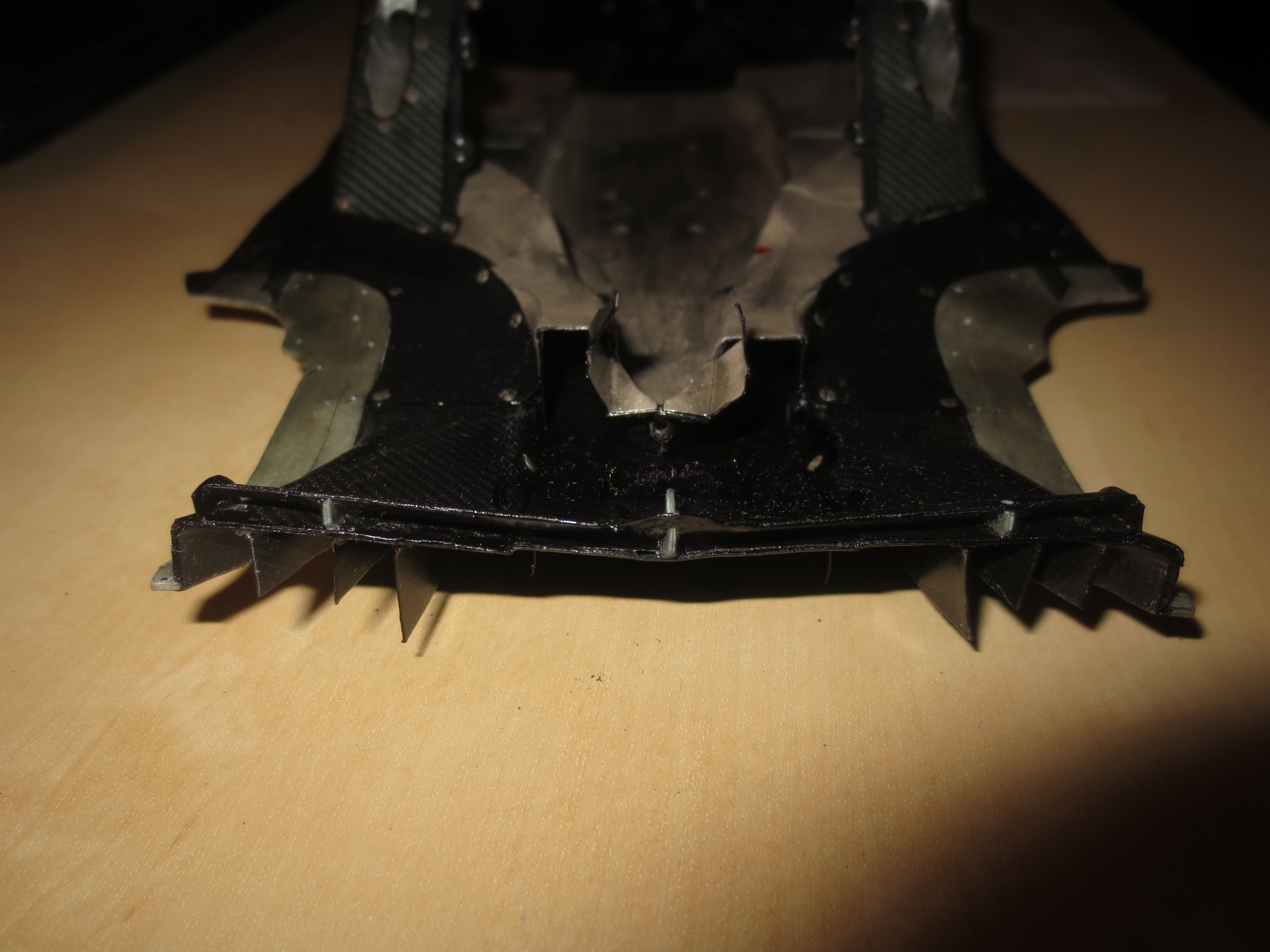
The rear of the floor with the diffuser. Very good visible is the diffuser gurney which helps to prevent a stall on the diffuser underside. With the new restriction of the diffuser height mid of 2011, teams switched from the classic diffuser gurney to a slotted gurney which is more like a little wing at the top of the diffuser. Another tweak to handle the new diffuser height restriction of 125mm (it's actually not new any more in 2013/14), was to expand more in width. So, the diffuser rise starts with a width of just about 700mm and expands to the rear to the full 1000mm (or slightly below).
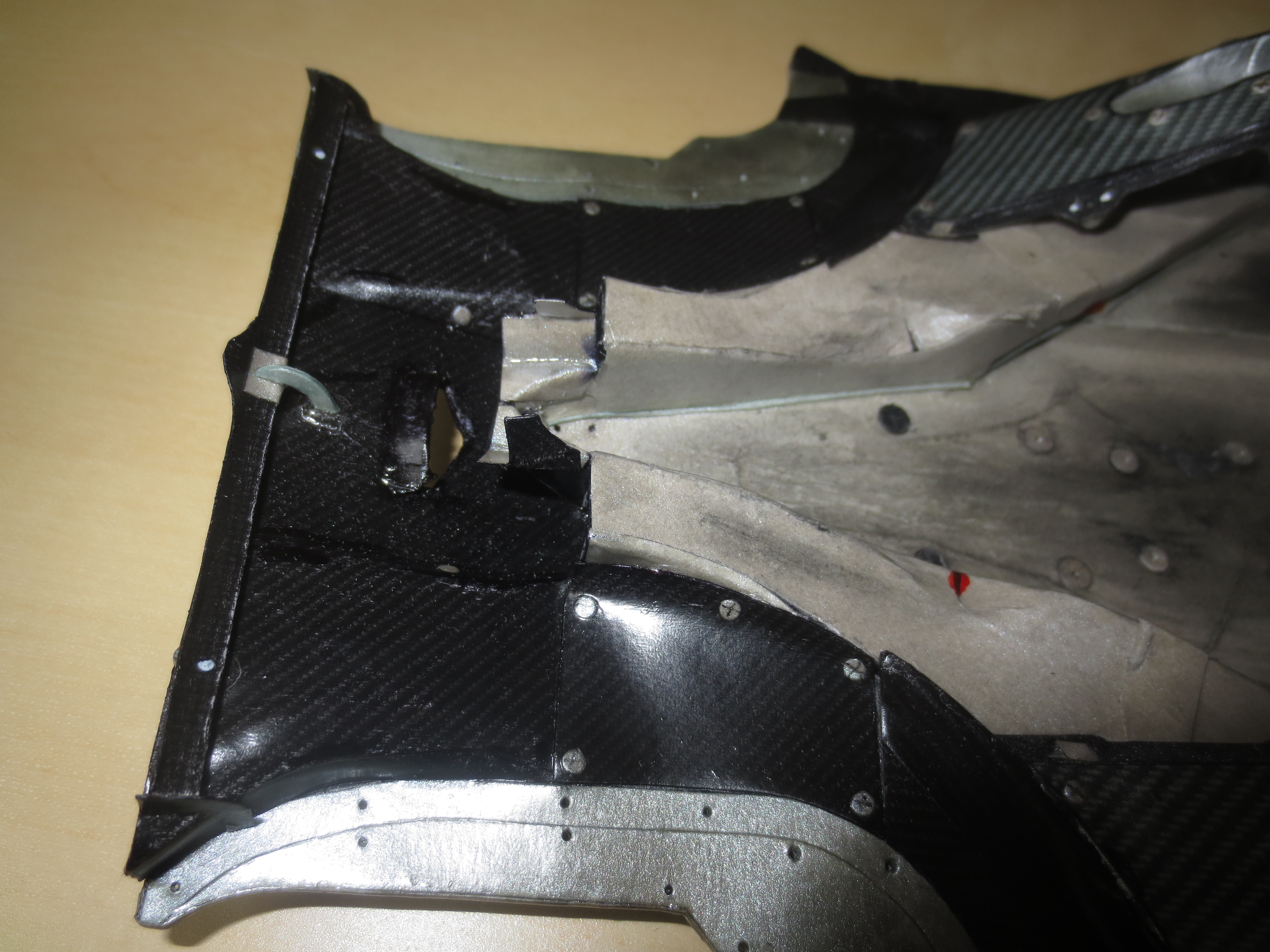
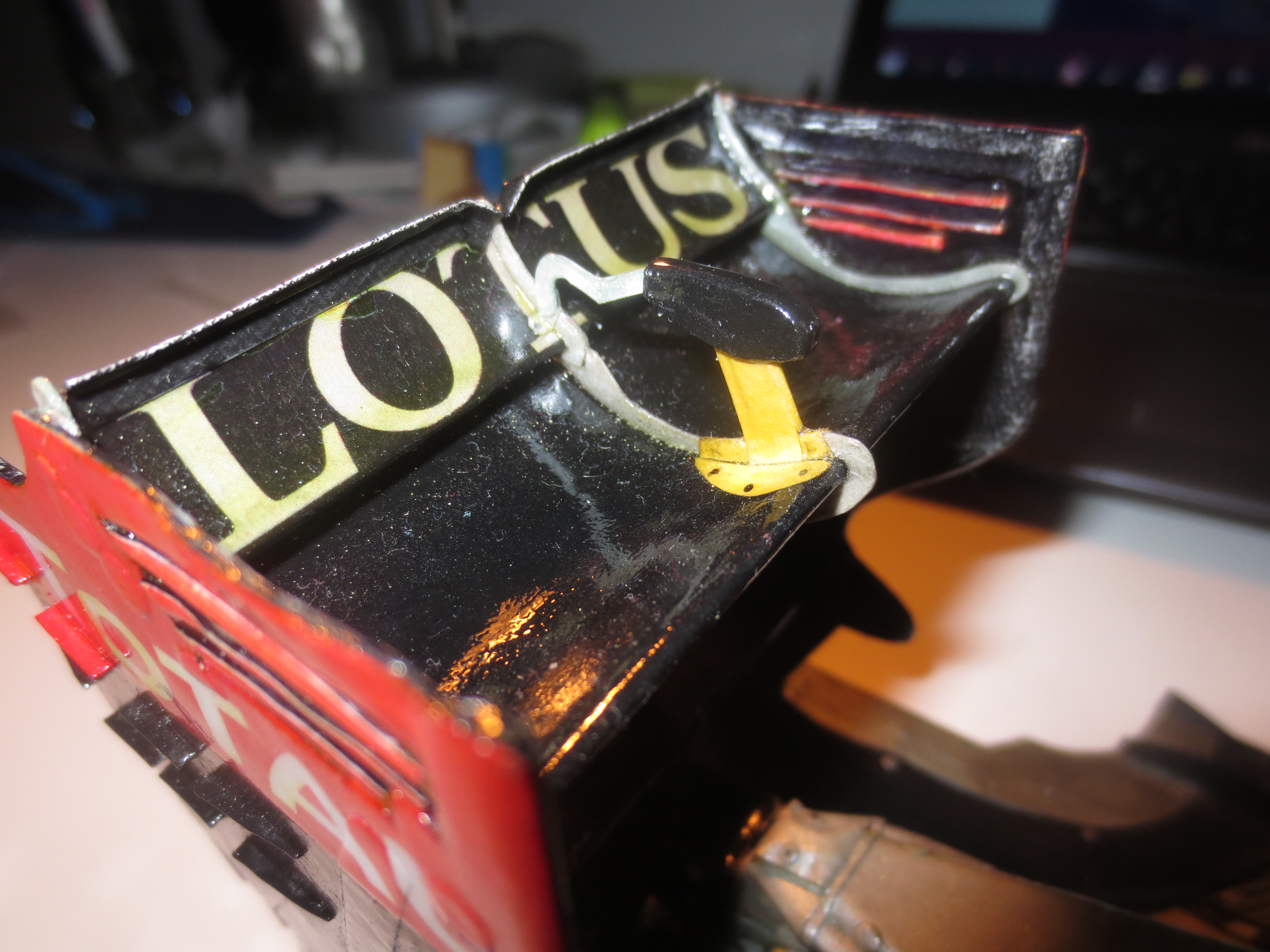
The diffuser viewed from the rear. That's a very good view to see why it's called "slotted gurney". It's not actually a gurney, but a little wing with a gap to the top surface of the diffuser. Often this wing is also provided with a little gurney itself.
The Underbody from below. You can see all the fixing bolts where the floor is fixed to the chassis and the engine. Notice the different wear of the three skid block pieces.
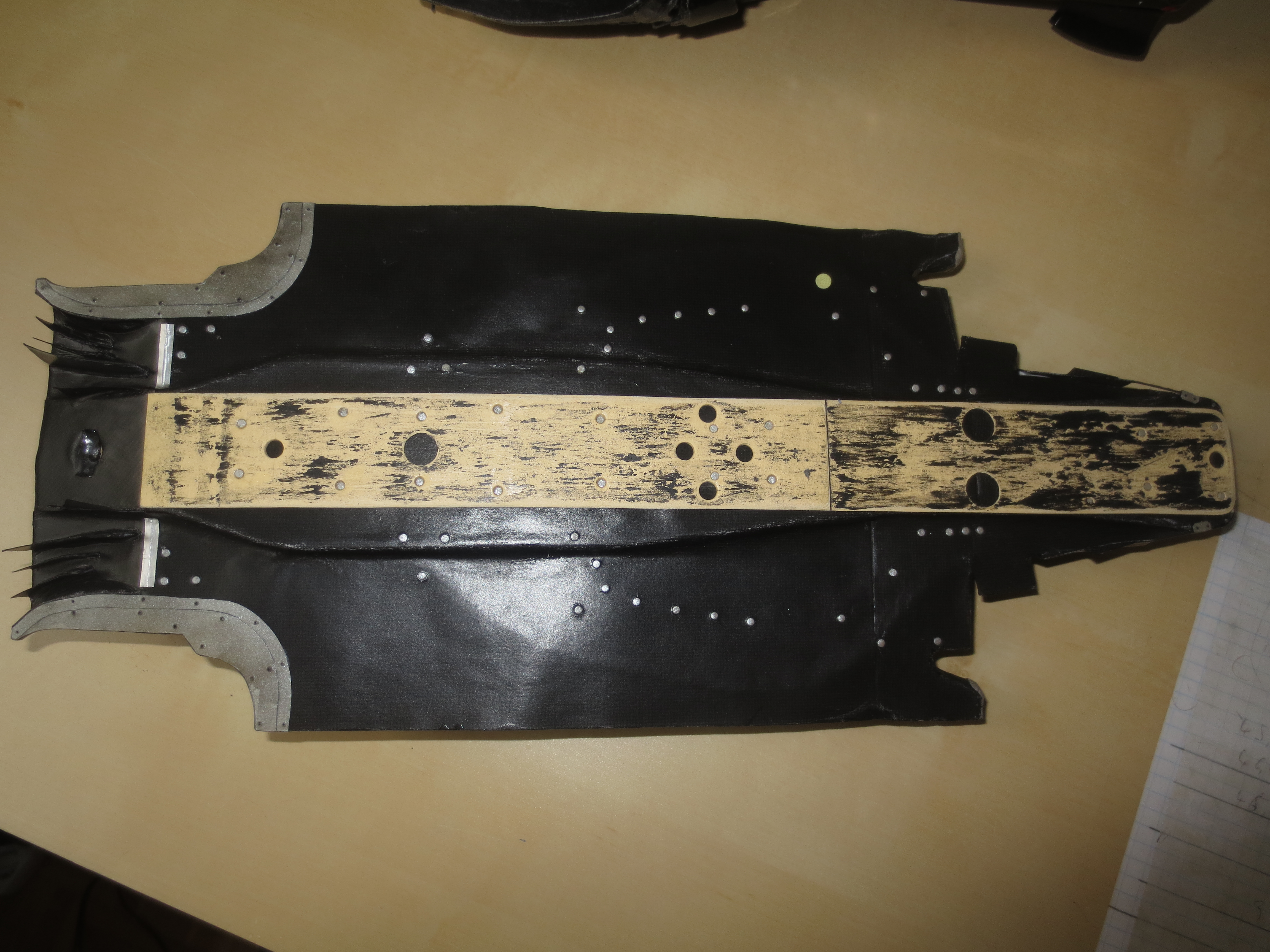
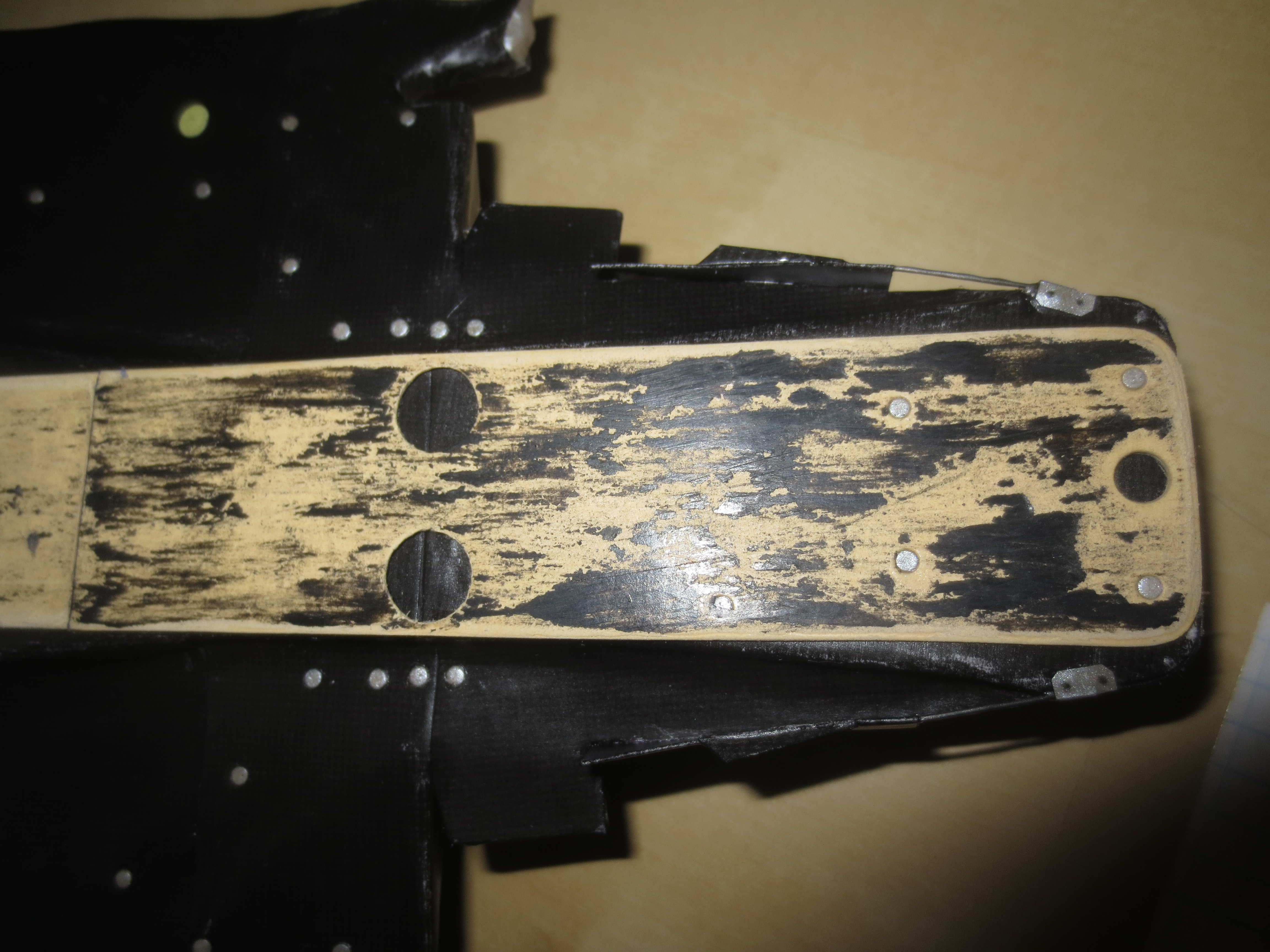
As already visible at the top picture, the Skid Block is splitted in three pieces (permitted by the regulations). This shows the front piece which is fitted to the T-Tray and is therefore the element which mostly slides on the track.
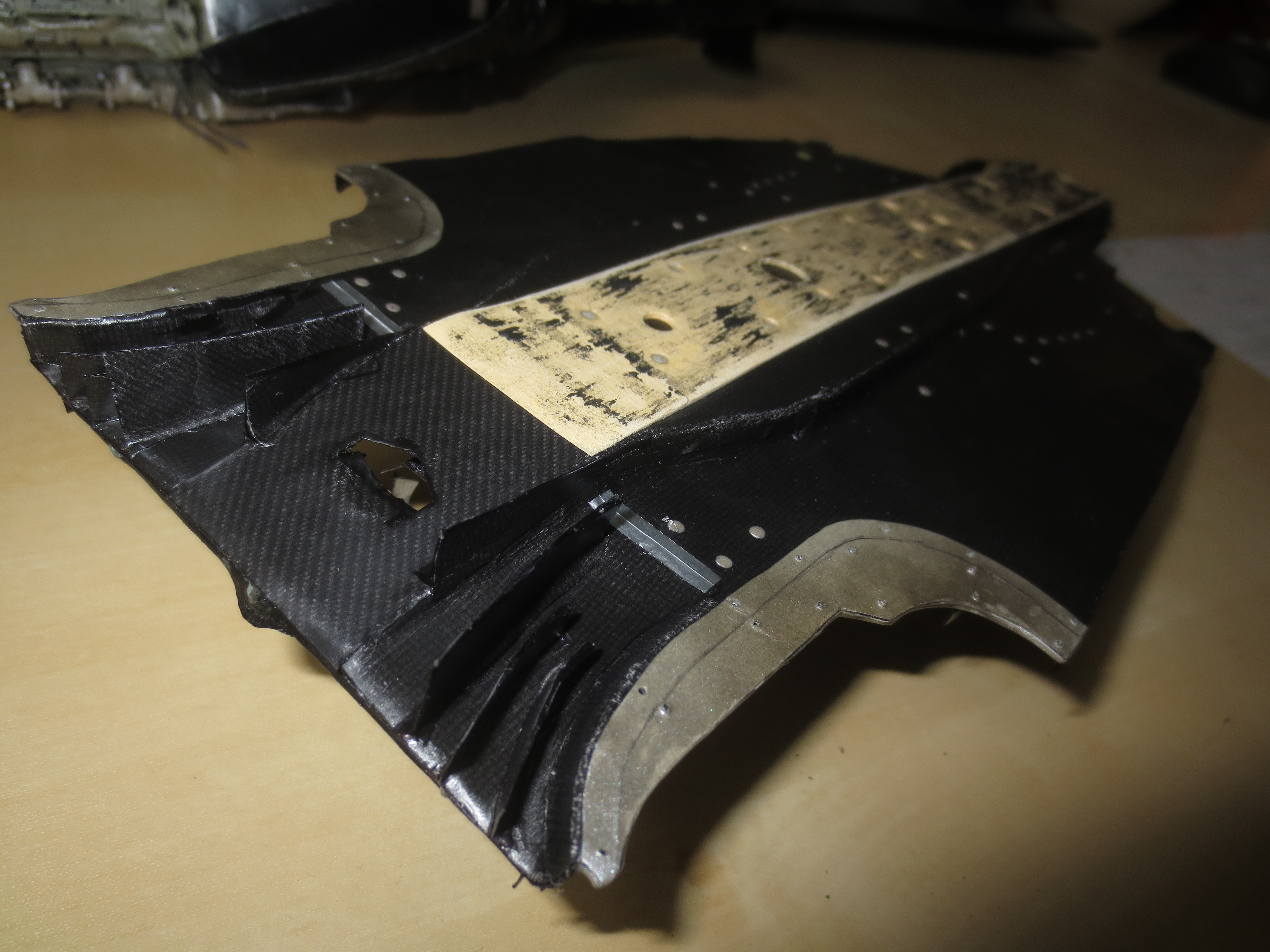
A good view on the important heat shields which prevent floor damage due to hot exhaust gases. The shedding edge you can see is the area, where the exhaust plume enters the floors underside. Also notice the different CFRP structures at the diffuser.
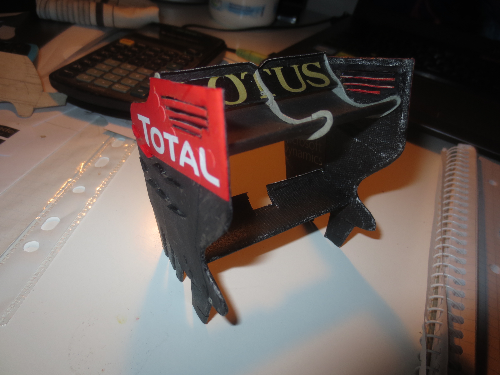
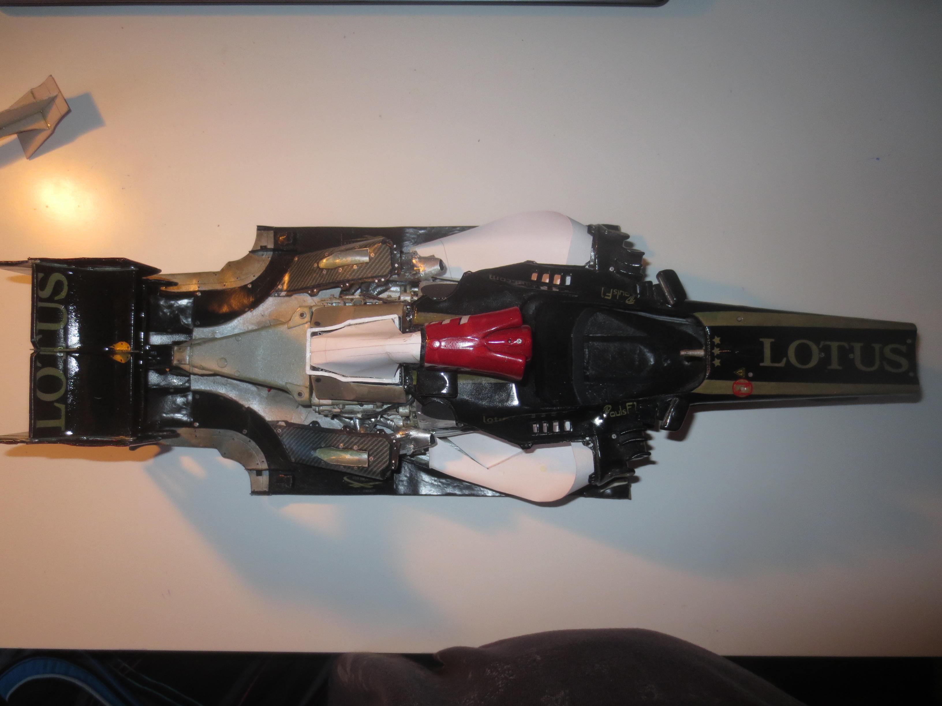
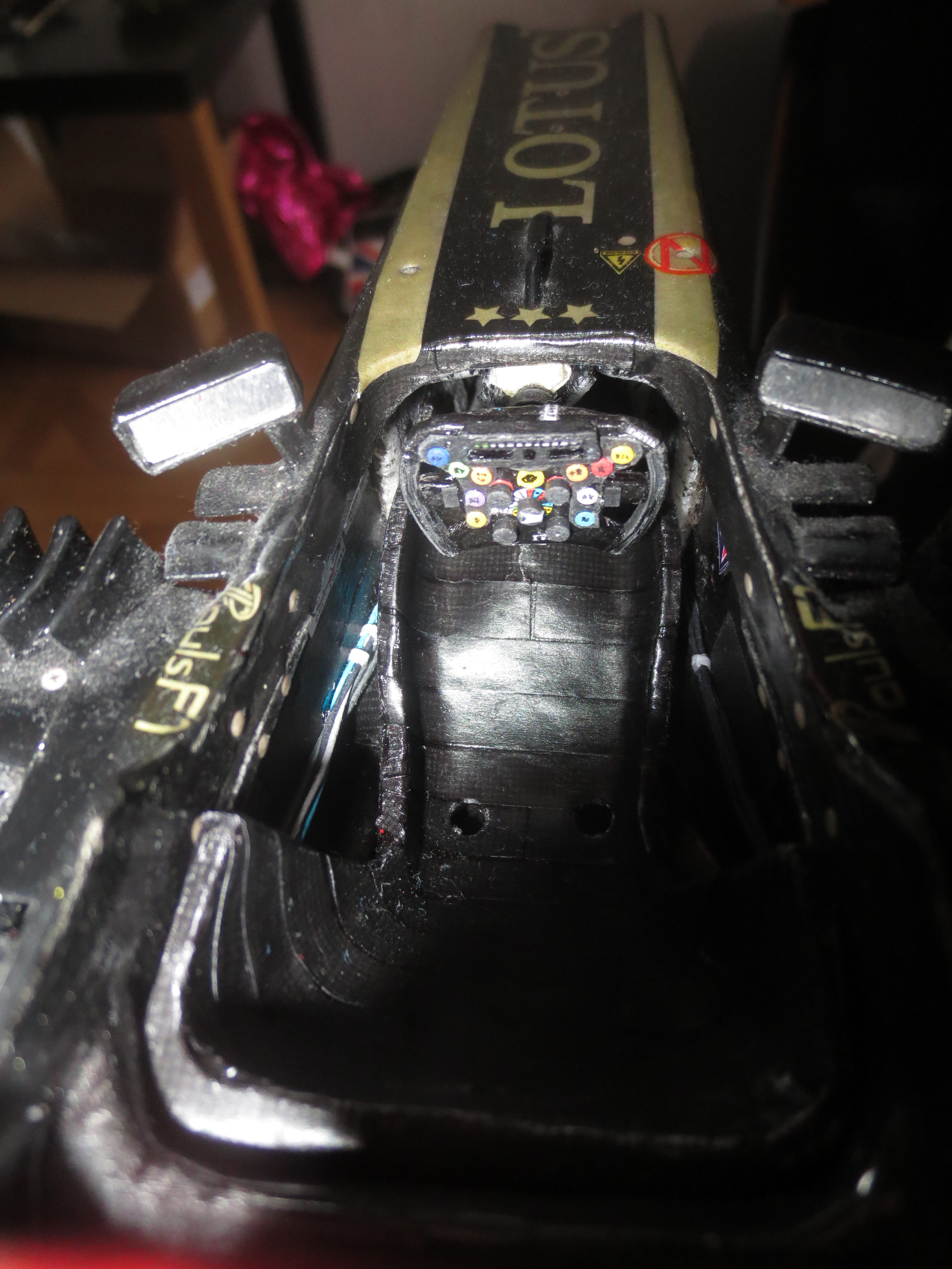
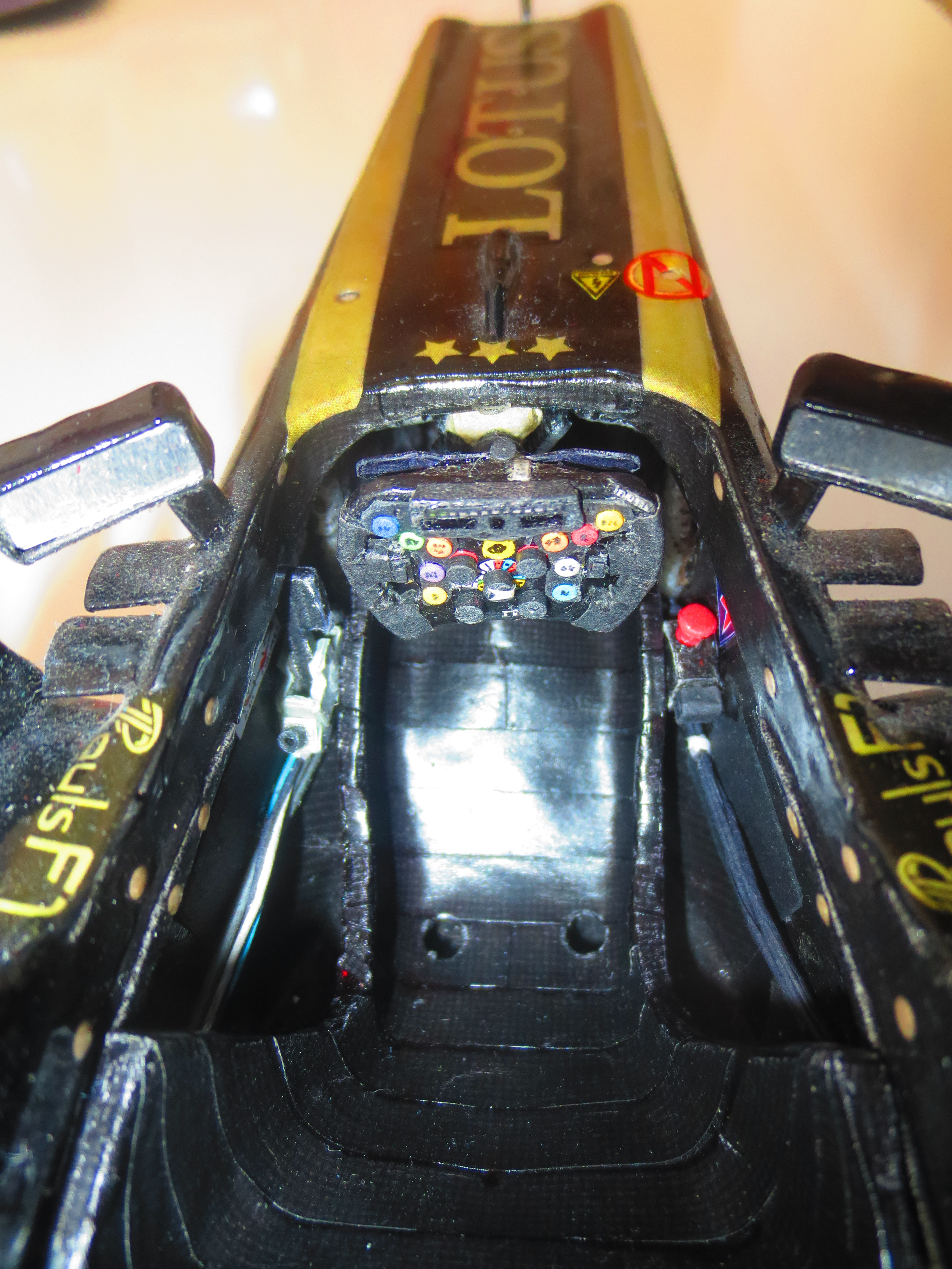
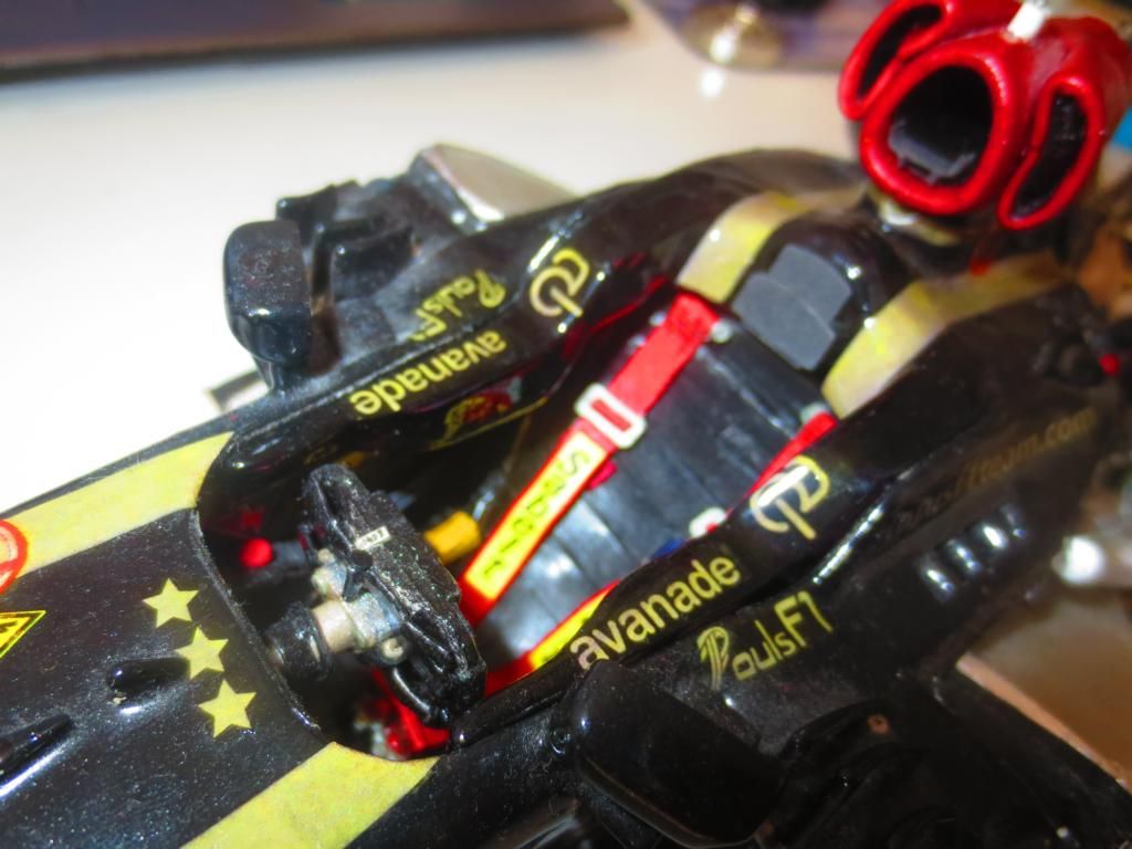
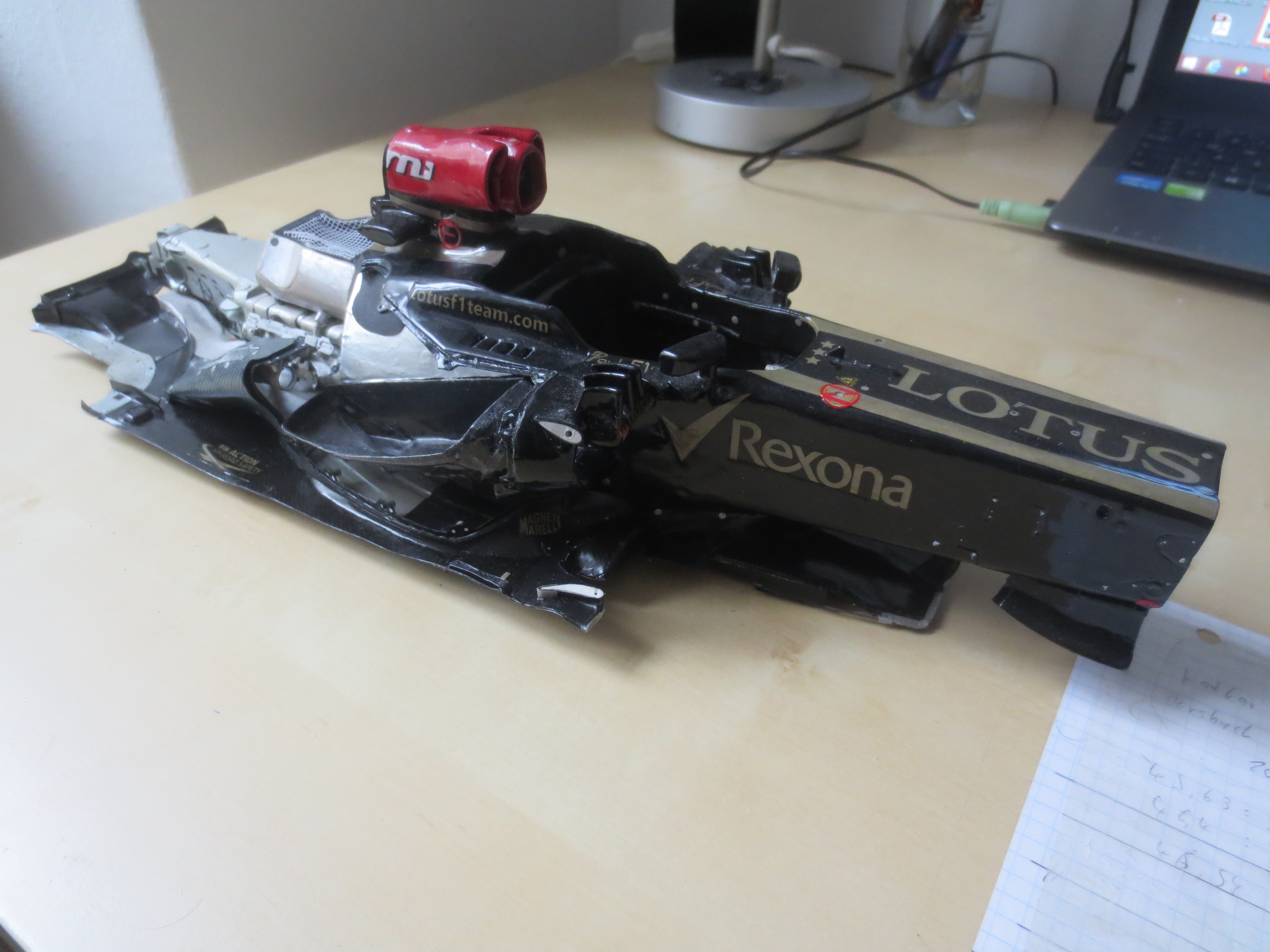
The car in current state. Still no end in sight, but slowly you can imagine whereabouts this project will lead...
That's it for now! Cheers,
Paul


