[KVRC] Khamsin Virtual Racecar Challenge 2016

Post here information about your own engineering projects, including but not limited to building your own car or designing a virtual car through CAD.
wesley123
wesley123
204
Joined: 23 Feb 2008, 17:55

Re: Khamsin Virtual Racecar Challenge 2016

Post

Personally, I'd think that makes the whole thing way more complicated, as it would involve mechanical placement, and as such, require changes in weight distribution.

Some might want to incorporate the radiators in the front and keep the sidepods clean, while others might choose otherwise. This would give huge changes to the applied CoM, which is pretty much correct in the current rule set. So if you want to apply such a thing, that would require changes(which incorporates a much larger variety of settings). Also an issue would be the tires. Front engined cars have a different balance, and thus require different tires(ie same size all around)

It's a fun suggestion and i would love to see it applied, but in a sense of execution it makes the whole thing more complicated.
"Bite my shiny metal ass" - Bender

User avatar
LVDH
46
Joined: 31 Mar 2015, 14:23

Re: Khamsin Virtual Racecar Challenge 2016

Post

julien.decharentenay wrote:Hi. I made some progress on the pressure on intake and exhaust aspect. It will be reported in the next round of results and is extracted using ParaView. We will see what the results look like.

However I need some input on finding the relevant way to present it. At the moment, I am extracting the pressure integrated over the whole intake/exhaust area. It is reported for each individual intakes and exhausts (ie 4 values in total: 1 for the cooling intake, 1 for the cooling exhaust, 1 for the engine intake and 1 for the engine exhaust). The surface integrated pressure unit is Pa.m2 or N.

I am also reporting it normalised by 1/2*rho*v*v so that it is homogene to a m2 and should be independent from the velocity. On of the aspect of this approach is that it combined both pressure and surface area.

What do you think?
I think (however, with not putting enough thought into it yet) what we should look at is total pressure flux.
The way how the BCs are currently implemented in OCCFD and in the challenge, I think it boils down to averaging the total pressure at the special surfaces.


Regarding this cool rendering:
I am not so sure about front engined cars. It would be fun and so on but sounds like a lot of work for the KVRC team.

However, more than once I played around with front a mounted cooling package. To fully exploit this we would need some more freedom with the cooling exit. It would be nice if we could rotate it next season.

User avatar
LVDH
46
Joined: 31 Mar 2015, 14:23

Re: Khamsin Virtual Racecar Challenge 2016

Post

OK,
I think there are good reasons for front engined cars only:

It would be somewhat new but not too different from this season.

Maybe with us all developing new cars and putting all this effort into it, we could find out if that Nissan entry from this year's Le Mans truly had potential or was a pure marketing gag.

User avatar
CAEdevice
49
Joined: 09 Jan 2014, 15:33
Location: Erba, Italy

Re: Khamsin Virtual Racecar Challenge 2016

Post

Thinking about a (fascinating) front engined car, I think about the Panoz example not about the Nissan (front engine but front traction too, at least during 2015 attempt).

User avatar
CAEdevice
49
Joined: 09 Jan 2014, 15:33
Location: Erba, Italy

Re: Khamsin Virtual Racecar Challenge 2016

Post

A summary of my experience with OCCFD during KVRC 2015.
  • 1) the "very stable" option has been very useful to solve the convergence issue
  • 2) the "standard solution" solver (running on Windows) often (2 times over 3) has covnergence issues: this is very limiting, considering that the issue can happen after some hours of simulation. The standard solver is almost unusable, and the "very stable" one gives quite different results when the car heavily uses vortex management to improve the df
  • 3) it would be great to have a transient solution, but I can imagine it would have a great computing cost
  • 4) it would be useful to have the possibilty to generate an editable "openfoam case folder" so that the solution could be run with openfoam (windows porting/linux/virtualboxes ...).[/i] >>> SOLVED (it is enough to work with the folders created by OCCFD).
  • 5) it would be useful, especially for the beginners, to use the "function" instruction in the "CASE/system/controlDict" file, to save drag and downforce data for single components like front wing and e rear wing (and maybe the floor, but it would be necessary to add an additional "patch" for it).
  • 6) larger pictures from the auto post processor (1500x1000, or simply zooming the car more than now)

User avatar
machin
162
Joined: 25 Nov 2008, 14:45

Re: Khamsin Virtual Racecar Challenge 2016

Post

So I guess that's pretty much KVRC 2015 over....

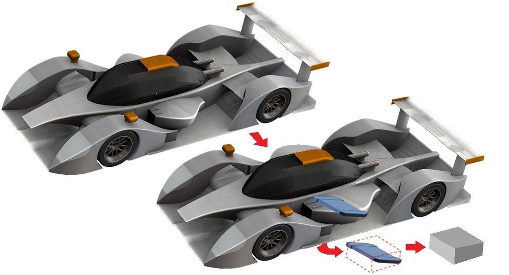
Hopefully it looks like Julien will be able to run the intake and outlet pressure integrals next year, which will get rid of the need for complicated inlet and outlet rules... but we still need to make sure the side pods themselves are realistic... I think the change mid-way through this year went some way, but IMO they need to be bigger still.. particularly in the longitudinal direction to take account of the fact the radiator will be lent over... since the space immediately in front of and behind the radiator needs to be "clear" to let airflow through the radiator, this could easily be accounted for by a solid cuboid of given dimensions that needs to be fully retained within the car's bodywork between the intake and outlet positions. This would also be quick and easy to check for rule compliance ("is it visible from the outside?").

(CAE Device's car used for illustration only because it is easy to show what I mean on it because of the exposed side-pods)

Image
COMPETITION CAR ENGINEERING -Home of VIRTUAL STOPWATCH

User avatar
CAEdevice
49
Joined: 09 Jan 2014, 15:33
Location: Erba, Italy

Re: Khamsin Virtual Racecar Challenge 2016

Post

Very interesting Machin!

It would be a great improvement. I wonder wich would be the boundary condition on the inlets/outlets (at the moment the inlet velocity is a BC on the inlet surface).

User avatar
machin
162
Joined: 25 Nov 2008, 14:45

Re: Khamsin Virtual Racecar Challenge 2016

Post

Good question... I'm not sure how that works either.... does the boundary condition effectively mean the model "sucks in" a pre-determined amount of air per second, regardless of where the inlet is positioned, and the new pressure measurement is what is needed to "pull in" that pre-determined amount of air? I guess that's a question for Julien or Chris maybe?
COMPETITION CAR ENGINEERING -Home of VIRTUAL STOPWATCH

User avatar
CAEdevice
49
Joined: 09 Jan 2014, 15:33
Location: Erba, Italy

Re: Khamsin Virtual Racecar Challenge 2016

Post

A different approach would be to leave completely free the design of the cooling duct and to model the heat exchanger box as "porous", computing on that box the delta between the inlet/outlet surfaces pressure x area resultants (or directly the airflow, that is simpler). I think OpenFoam would allow it, but I've been studing it only for a few months (with my old software, FloEFD, it was quite easy to do).

User avatar
machin
162
Joined: 25 Nov 2008, 14:45

Re: Khamsin Virtual Racecar Challenge 2016

Post

Or model a flat plate with one central round hole of a specified diameter (effectively; an orifice plate), and then measure the air flow through the plate...

...however, both those ideas require internal flow to be modelled and I think that was something Julien suggested that we steer clear of... I suspect that Julien's way is probably the best compromise as he's probably thought a lot more (and knows a lot more) about it than us!
COMPETITION CAR ENGINEERING -Home of VIRTUAL STOPWATCH

User avatar
variante
138
Joined: 09 Apr 2012, 11:36
Location: Monza

Re: Khamsin Virtual Racecar Challenge 2016

Post

machin wrote:...since the space immediately in front of and behind the radiator needs to be "clear" to let airflow through the radiator, this could easily be accounted for by a solid cuboid of given dimensions that needs to be fully retained within the car's bodywork between the intake and outlet positions.
If you try to insert such cuboid in an F1 sidepod you would observe the inability of the bodywork to fully contain said box.
Sidepods are well scupted around radiators, and imposing the "box rule" would prevent KVRC participant from creating elegant geometries.

Also, 360000mm^2 of radiating surface cross section doesn't sound too unrealistic to me.

User avatar
machin
162
Joined: 25 Nov 2008, 14:45

Re: Khamsin Virtual Racecar Challenge 2016

Post

variante wrote: Sidepods are well scupted around radiators, and imposing the "box rule" would prevent KVRC participant from creating elegant geometries.
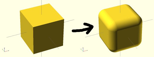
We could radius the corners...

Image

If you consider we have the same power as a current F1 car, our sidepods should be the same size if we are to maintain realism... and the current F1 cars use the full 1400mm width allowed...

Image

and at the widest point they're reasonably "boxy" (with the radius edges as per above):

Image


maybe a fixed "box" is too much... but do you agree that we should at least have some depth to the Radiator area...?
COMPETITION CAR ENGINEERING -Home of VIRTUAL STOPWATCH

User avatar
machin
162
Joined: 25 Nov 2008, 14:45

Re: Khamsin Virtual Racecar Challenge 2016

Post

Also... A cube, of the right size, doesn't have to preclude nice smooth side pods; after all a cube fits within a sphere, if the sphere is big enough... We just have to make the cube the right size to force people to use the right sized side pod... ;)
COMPETITION CAR ENGINEERING -Home of VIRTUAL STOPWATCH

User avatar
variante
138
Joined: 09 Apr 2012, 11:36
Location: Monza

Re: Khamsin Virtual Racecar Challenge 2016

Post

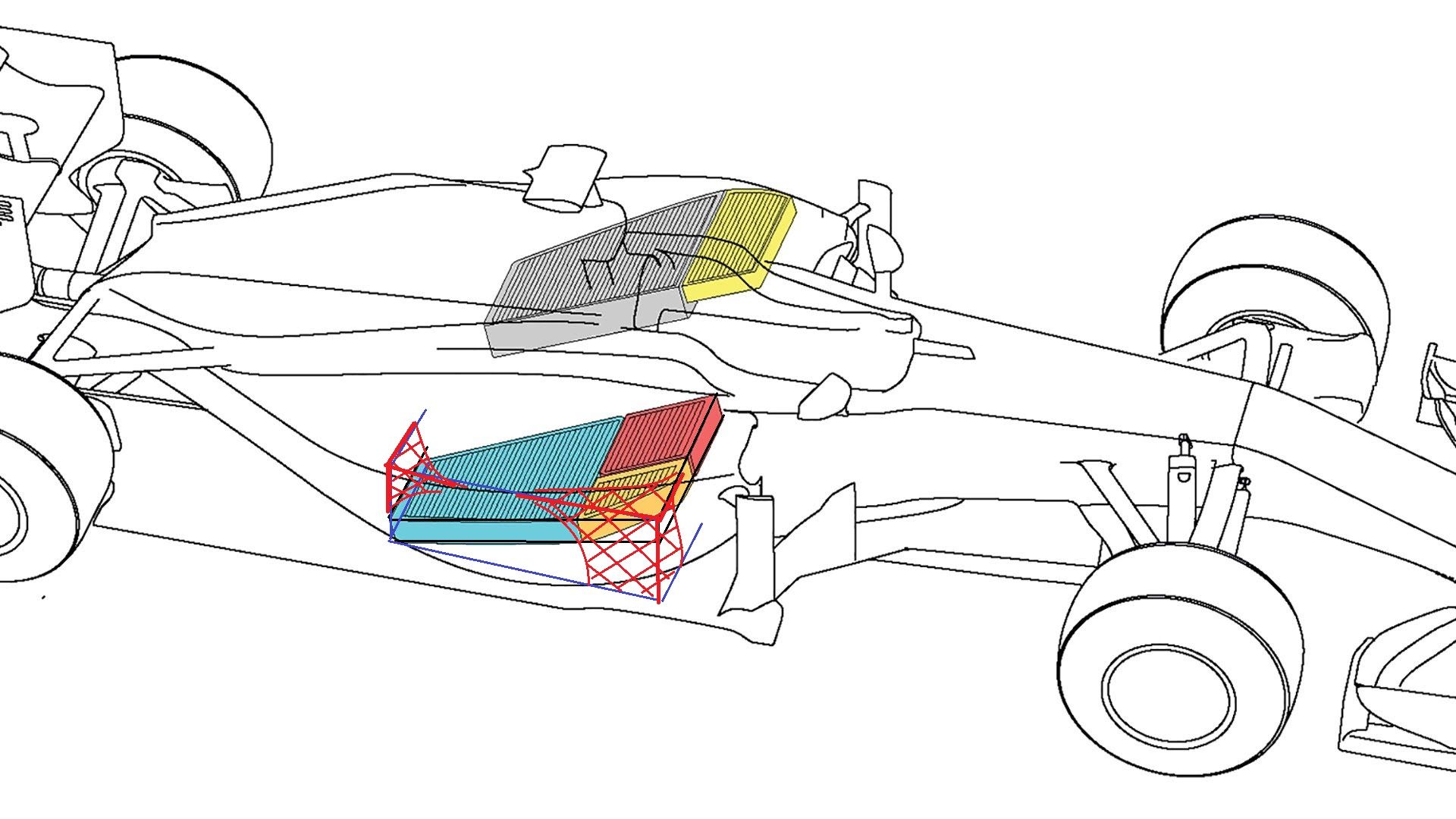
This is how much the box would not fit:
Image
Now imagine designing a bodywork around that... :D

F1 uses the full allowed width of 1400mm. My sidepods are 1600mm wide (ok, with a larger cockpit as well...) and have a squared section.

Also, imposing such box would force everybody to use a similar design; at this point it would be better to give directly a radiator surface around which to build anything without further limitations.

I agree that we could increase the level of realism around that area, maybe enhancing the "depth" of those volumes. I'm not sure how, at the moment.

User avatar
RicME85
52
Joined: 09 Feb 2012, 13:11
Location: Derby

Re: Khamsin Virtual Racecar Challenge 2016

Post

This comes full circle to what I propose a year or two ago about having supplied ancillaries that have to be placed into the bodywork volume.
IMO its something we should look at, especially if we want to attract people from professional backgrounds or those working towards it. Realism over fantasy designs is my preference, in KVRC, every year we have seen cars that are far more fantasy than realistic....because the rules allow it. Just look at the 2013 CSR car that Chris designed, that had bodywork effectively shrink wrapped around the minimum allowed volumes when in reality you couldnt do that due to heat etc.
Image
2014 was better but was still tight in places like the engine cover.
Image