i hope u all having a good day
well i was searching for more details about uprights because i am trying to design one so i found this topic http://www.f1technical.net/forum/viewto ... f=6&t=8861
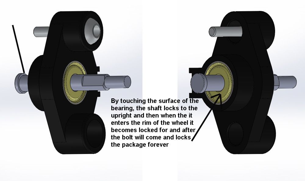
but the problem is that i couldnt understand how does the wheel shaft is assembled in the upright !!?
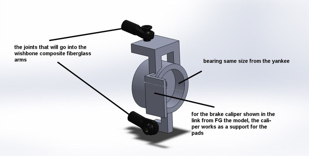
the pictures below shows a model from Yankee cars which i have, modeled it using solidworks so u can see how the shaft is locked to the upright and how the camber can be adjusted and the last picture is another model which i came up with using the same bearing the yankee upright uses, my next calculation would be about using a smaller exterior diameter bearing but for now it would be better to know how does the actual shaft locked in the actual upright ?
for the brakes the model is this one from FG http://rc-car-online.de/shop/en/product ... 1-set.html


