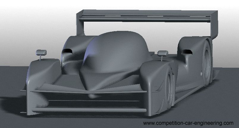
[KVRC] Khamsin Virtual Racecar Challenge 2016

Post here information about your own engineering projects, including but not limited to building your own car or designing a virtual car through CAD.
User avatar
CAEdevice
49
Joined: 09 Jan 2014, 15:33
Location: Erba, Italy

Re: Khamsin Virtual Racecar Challenge 2016

Post

machin wrote:Gets my approval.

Oh yeah... And if I or anyother entrant forgets to enter a car in a round, can the previously submitted car be used for results... Unless the entrant SPECIFICALLY states that they want to withdraw their team from the competition. It would mean going on holiday doesn't ruin your championship, and means the entrant numbers stay high throughout the season...
Good idea. Once (last year) I re-submitted at 23.00... I would have lost the possibility to race in case (ex.) of internet blackout.

You have me another idea: what about running a previous car instead (or alternatively) of giving a penalty?

User avatar
CAEdevice
49
Joined: 09 Jan 2014, 15:33
Location: Erba, Italy

Re: Khamsin Virtual Racecar Challenge 2016

Post

PS: we should consider that, except for the first or second race; the best way to improve is to develop the car of the previous race.

etsmc
etsmc
7
Joined: 04 Apr 2012, 13:20

Re: Khamsin Virtual Racecar Challenge 2016

Post

Got my results looking forward to seeing where i came.
Total drag: 2030.29 N 
Front wing(s) drag: 285.34 N 
Rear wing(s) drag: 326.12 N
Drag coefficient - Cd: 0.94
Drag area - Cd.A: 1.69 m2
Total Downforce: -4666.32 N 
Front wing(s) downforce: -576.09 N 
Rear wing(s) downforce: -1497.37 N
Downforce coefficient - Cl: -2.16
Downforce area - Cl.A: -3.89 m2
CoP of downforce: 1.491 m along streamwise (Y) direction from Y = 0.00 m.
KVRC Only: Corrected CoP of downforce: 1.570 m along streamwise (Y) direction from Y = 0.00 m.

The pressure at intake and exhaust are:

Engine intake, Area: 0.021m2 - Compliant 
Surface integral of pressure: 12.51 Pa.m2
Engine exhaust, Area: 0.010m2 - Compliant 
Surface integral of pressure: -7.51 Pa.m2
Cooling intake, Area: 0.399m2 - Compliant
Cooling exhaust, Area: 0.400m2 - Compliant 
Differential of surface integral of pressure: -343.98 Pa.m2

User avatar
machin
162
Joined: 25 Nov 2008, 14:45

Re: Khamsin Virtual Racecar Challenge 2016

Post

Looks like you are still struggling with cooling...

If you look at your car:-
etsmc wrote:Image
Compared to my car (round 1 submission, which achieved the full 100% power) below:-

Image

...you can see that my car directs a lot more air through the suspension to the cooling inlets (essentially the whole area in shadow beneath the upper front wing feeds beneath the suspension cover.... whereas your car directs most of the air up and over the front of the car... so the only air you have which can feed your cooling inlets is the small inlets you have at the front, and any air that goes under the front splitter/diffuser... but remember that some of that air will go under the car to the rear diffuser....

So my tip would be to try a more "formula-car" style front end....

Audi has used the same "through-flow" philosophy with their latest WEC LMP01 car:-

Image
COMPETITION CAR ENGINEERING -Home of VIRTUAL STOPWATCH

etsmc
etsmc
7
Joined: 04 Apr 2012, 13:20

Re: Khamsin Virtual Racecar Challenge 2016

Post

My heat exchangers are infront of my front suspension and the intake is in a high pressure area. Really don't get what is going on. Will have to have a look at results in paraview
A little perplexed

User avatar
CAEdevice
49
Joined: 09 Jan 2014, 15:33
Location: Erba, Italy

Re: Khamsin Virtual Racecar Challenge 2016

Post

You should also consider the direction of the air flow (ideally normal to the inlet surface) and the pressure on the cooling outlets.

User avatar
machin
162
Joined: 25 Nov 2008, 14:45

Re: Khamsin Virtual Racecar Challenge 2016

Post

etsmc wrote:My heat exchangers are infront of my front suspension and the intake is in a high pressure area.
Where are the outlets then?

EDIT:

I wonder if you just need to make the front inlets much bigger: The Nissan LMP had front mounted heat exchangers and their front inlets were pretty big...

Image
Last edited by machin on 15 May 2016, 22:54, edited 1 time in total.
COMPETITION CAR ENGINEERING -Home of VIRTUAL STOPWATCH

User avatar
RicME85
52
Joined: 09 Feb 2012, 13:11
Location: Derby

Re: Khamsin Virtual Racecar Challenge 2016

Post

In front of the front suspension is an interesting idea. I assume the outlets are in the usual place and the air is ducted around the survival cell?

Cant wait to see the results to see how Machin's and my car compare.

Chris, is there any chance of having the intro bodywork changed slightly? I dont know about Richard, but I find the front wheel pods could do with being a bit shorter (start a bit further back). This would give us a bit more area to play with for creating front downforce. I found it difficult to add downforce at the front without affecting the cooling (which we obviously cannot move to counter issues faced).

User avatar
machin
162
Joined: 25 Nov 2008, 14:45

Re: Khamsin Virtual Racecar Challenge 2016

Post

I'd personally prefer the supplied parts to remain as they are... as I'm not doing any CFD myself any changes now would throw out my development plan! This might mean that the Intro class ("KVRC2 Class" ?) can't reach the ultimate downforce levels as the main class ("KVRC1 Class" ?), but I'm OK with that.... as it is the same for all KVRC2 competitors....

Did Will submit for Round 1? It turns out that my mate is the person behind "Machin's Shiny Melon" (his idea of a joke, based on my receding hair-line and shiny forehead -with some "friends" you don't need enemies right?). He used my basic bodykit as a starting point. That might mean we have 4 cars in the Intro/KVRC2 class?
COMPETITION CAR ENGINEERING -Home of VIRTUAL STOPWATCH

User avatar
RicME85
52
Joined: 09 Feb 2012, 13:11
Location: Derby

Re: Khamsin Virtual Racecar Challenge 2016

Post

I have no issue with the levels being different to the main class, it was more about being able to balance the car easier.
My current car is similar to yours and the balance is more rearward than I would like but not massively off, at least I have 100% engine power to help counter some of the deficiencies in lap time.
I have tried a version with a double deflection diffuser at the front but found it cut engine power to only 40%. I plan on looking at the front diffuser solution to see if there is a way to improve the engine power (is the lack of power due to the diffuser creating such a low pressure area ahead of the cooling inlet?)
I have tried diveplanes on the front corners of the car to see if that helps with the balance, I have also tried some behind the front wheel where the fairing curves inboard so gives a good volume that can be used for airfoils but found they didnt particularly do anything to the balance (the OCCFD result didnt show any change on the downforce bar chart).

User avatar
machin
162
Joined: 25 Nov 2008, 14:45

Re: Khamsin Virtual Racecar Challenge 2016

Post

Yeah, I'm lacking front-end downforce too... But there are still some things I want to try. At the end of the day we can always lower the AoA of the rear wing to get the balance. I think we should be pretty well placed for the low downforce rounds.

I suspect an extreme front diffuser directs too much air over the top of the side pods. We have to be careful not to create too much up wash. Having said that I managed to get loads of pressure in round 1: well over the minimum required for 100% power. So I know I can play a bit more with the front end; I.e. Sacrifice some pressure for more downforce...
COMPETITION CAR ENGINEERING -Home of VIRTUAL STOPWATCH

User avatar
RicME85
52
Joined: 09 Feb 2012, 13:11
Location: Derby

Re: Khamsin Virtual Racecar Challenge 2016

Post

The front diffuser I had designed wasn't massive, it was only as high as the lowest face of the suspension template.
I too had some wiggle room with the pressure with the non diffuser version.

As you say, for the low downforce rounds the KVRC2 cars should be pretty competitive.

I know some changes could be made at the rear (AoA, changing diffuser, etc) but I would like to try and improve the front before going down the removing rear performance route.

I understand if people don't want to talk airfoils they may be using, but worth a try...what profiles have people tested? Actual NACA profiles or profiles designed yourself?
I have been up until recently been using the rear wing profile that came with the car Chris supplied last year but have changed to using the Red Bull rear wing profiles that Scarbs shared.

Back to the cooling...is my theory in my previous post about the front diffuser creating a low pressure area causing the cooling to not work correct? If so would a barge board behind the front suspension to collect the air exiting the diffuser and guide it to the cooling inlet be the way to improving engine performance? (my thinking being it would re-energise the air thus creating a higher pressure at the inlet). Sound theory or completely off the mark?

etsmc
etsmc
7
Joined: 04 Apr 2012, 13:20

Re: Khamsin Virtual Racecar Challenge 2016

Post

machin wrote:
etsmc wrote:My heat exchangers are infront of my front suspension and the intake is in a high pressure area.
Where are the outlets then?

EDIT:

I wonder if you just need to make the front inlets much bigger: The Nissan LMP had front mounted heat exchangers and their front inlets were pretty big...

http://media.crash.net/original/AU1270243.jpg
my outlets are
1. just behind the front suspension each side of the foot box template
2. (this was the rushed one due to the other not being big enough) is just in front of the foot box template. (copped a penalty for this as it was not far enough back #-o )

is there any way we can find out if the issue is on the intake side or the exhaust side of the cooling?? :?

I think I will work on a larger cooling exhaust each side and a slightly larger intake. I thought that with the area of the intake there would be sufficient high pressure to supply enough air to the heat exchanges.

I will try and get some SurfaceLic images up from ParaView later.

Full results can be found here https://mercurymotorsport.wordpress.com ... rburgring/


EDIT:
So a couple of surfacelic images from paraview showing the airflow into the intake through the x and z-axis.
Image
Image
Could the issue be the areas of circulating air at the bottom of the intake at the edges and another at the top of the rear of the heat exchanger?

User avatar
CAEdevice
49
Joined: 09 Jan 2014, 15:33
Location: Erba, Italy

Re: Khamsin Virtual Racecar Challenge 2016

Post

I am almost sure that you have positive pressure on the cooling outlet surface (considering the BCs and Bernoulli's theorem). The inlet cooling duct could be improved too.

etsmc
etsmc
7
Joined: 04 Apr 2012, 13:20

Re: Khamsin Virtual Racecar Challenge 2016

Post

CAEdevice wrote:I am almost sure that you have positive pressure on the cooling outlet surface (considering the BCs and Bernoulli's theorem). The inlet cooling duct could be improved too.
so looking at the x-axis your saying as the duct is getting smaller then the pressure is building in the duct? and the rear of the heat exchanger is seeing positive pressure?
so a fix may be to have a larger cooling outlet therefor the duct would not be getting as small and not be building up pressure. :?: