Honda Power Unit Hardware & Software

All that has to do with the power train, gearbox, clutch, fuels and lubricants, etc. Generally the mechanical side of Formula One.
User avatar
PlatinumZealot
559
Joined: 12 Jun 2008, 03:45

Re: Honda Power Unit

Post

And another thing that People sometimes forget.

The valves in F1 as far as I have seen use "buckets" and are directly underneath the camshaft. This means that the cylinder bores are centred along a straight line. No offset cylinders like a VR6 to enable a more compact block.

If the valves were actuated with rockers though. It is possible to have the cylinders in a staggered formation, and hence a shorter - but wider, block.
๐Ÿ–๏ธโœŒ๏ธโ˜๏ธ๐Ÿ‘€๐Ÿ‘Œโœ๏ธ๐ŸŽ๐Ÿ†๐Ÿ™

Racing Green in 2028

roon
roon
412
Joined: 17 Dec 2016, 19:04

Re: Honda Power Unit

Post

dmjunqueira wrote:
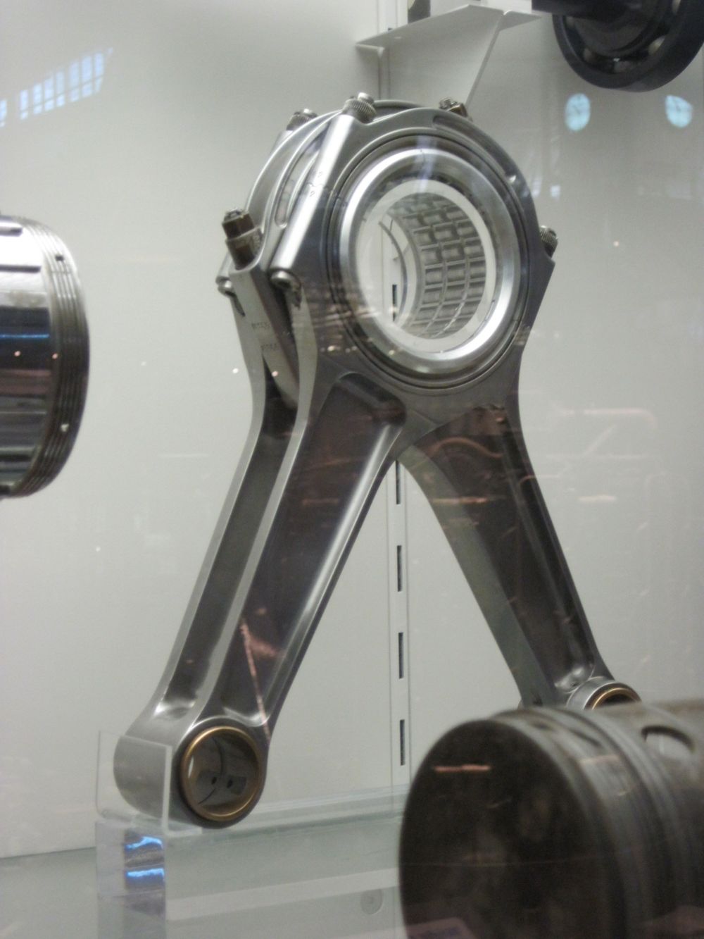
roon wrote: Join the piston connecting rods together. Shared conrod big-ends, or some other form of linkage to allow opposing cylinders to occupy the same plane. No offset of the cylinders between banks. Voila: shorter crank, shorter block, and you still satisfy the three crank throw rule. Regulations regarding connecting rod design are pretty open aside from material specifications
Like this?
http://www.ing.unitn.it/~colombo/MOTOTI ... age053.jpg
https://upload.wikimedia.org/wikipedia/ ... s_fig5.jpg
Yes, or:

Image

hemichromis
hemichromis
14
Joined: 17 Nov 2015, 15:00

Re: Honda Power Unit

Post

Am i the only one who chooses to believe that these engines work by magic and fairy dust?

I might be in the wrong forum.

Tommy Cookers
Tommy Cookers
643
Joined: 17 Feb 2012, 16:55

Re: Honda Power Unit

Post

coplanar rods save only a little length (what roon said), as modern bores are large and modern bearings are small (reason coplanars are in museums)
articulated (one coplanar type) rods will give motion differences between banks
coplanar rods will be less suited to very high rpm, but seem plausible current F1 mandated stroke and rpm used
early V8s etc used existing 4 cylinder flat cranks so coplanar rods were needed, side-by-side rods came long after the crossplane crank emerged
and after bore:stroke ratio was increased, reducing engine width for use beyond the high end big car market

EDITED to clarify dramatic intent ......
mandated 90 deg V could have (with balance unimpaired) any crank arrangement eg even all the throws at 0 deg, allowing ......
eg whole left bank firing simultaneously, then whole right....... (......just saying)
Last edited by Tommy Cookers on 16 Feb 2017, 10:58, edited 4 times in total.

User avatar
godlameroso
309
Joined: 16 Jan 2010, 21:27
Location: Miami FL

Re: Honda Power Unit

Post

So a semi big bang engine? Where 3 cylinders fire simultaneously? How about 2 simultaneously firing cylinders, or close to simultaneous? 1&4 3&6 and 2&5 each fire simultaneously(or very close)?
Saishลซ kลnฤ

ncassi22
ncassi22
31
Joined: 27 Apr 2013, 02:26

Re: Honda Power Unit

Post

glenntws wrote:Hey guys,

I'm new in this Forum but since this discussion is very interesting, I thought I could also talk a bit with you.

First: I'm very sure the engine was running in a Controller cylinder shutoff with one cylinder active on one bank and two others on bank 2. I'm also pretty sure , the distance between the ignitions was 300ยฐ - 180ยฐ - 240ยฐ. I took a look at the sound file in audacity and here's a little part of it colored by me:

http://fs5.directupload.net/images/170215/a58lxnsu.png

The yellow colored is the ignition on bank 1, the blue and green ones are on bank 2 I think.


Second: I'm also sure that the idea of the pistons without offset won't be the right one. This way of rod design won't be good at all for the high pressures. Additionally: The crankshaft will have to have the same length either way, and a cylinder offset will only help in regards to the intake System. The 20-25mm, which they lose lose from offset cylinders won't help much at all when looking at the placement of the turbocharger.


Third: While everybody thinks that TJI will come to the Honda engine, I think I have a idea of how this System could look like. I made 4 little Sketches which could explain the System fairly good.

Intake stroke: http://fs5.directupload.net/images/170215/l9om6db6.jpg

Mid-compression stroke: http://fs5.directupload.net/images/170215/zbs2e3kp.jpg

End of compression stroke: http://fs5.directupload.net/images/170215/x3flcwfm.jpg

Start of ignition: http://fs5.directupload.net/images/170215/fq8r3ey2.jpg

Now, I will explain you why I think this should work. At first, thanks to this design, all the requirements by the fia are fullfilled.
So, once the intake stroke starts, you get a pretty high amout of tumble in the chamber, which will - because of the gas Forces - clear out the prechamber. The prechamber has a ~5mm wide opening at the bottom, which is almost completely (0.1-0.3mm distance) closed at TDC. The prechamber also has several little holes all around. which can force the ignition arcs into the main chamber.

Mid-compression stroke, the engine will start injecting fuel. Since the piston has this pinnacle at the top (which also closes the prechamber), the fuel, if it's shooted in a narrow angle onto this Point, will automatically form a rich cloud of fuel-air mixture directly under the opening of the pre-chamber. At the end of the compression stroke, this very rich cloud will partly be forced into the pre-chamber, while the main chamber will retain the two tumble motions on both sides.

When starting the combustion, the movement in the prechamber will go down with big force thanks to the droplet-replicating shape. Since the main-opening is closed, fire arcs will go into the two chamber parts and will induce a combustion in the motion of the two tumbles, which in turn will make sure the combustion will happen as clear as it can.


Keep in mind, that these sketches are made pretty fast. I just think this is a way, Honda could do it like.

I'm no Student in mechanics or thermodynaics nor do I work in this sector (finishing high school right now in Germany). However, I'm working on a engine since 2 years. While it uses HCCI, I think the (pretty big) amount of knowledge I gained could help to find out at least a little bit more about the Honda engine :)
Possibly adding a valving system infront of the plug in your illustration might remove the need to compromise the crown in terms of assisting swirl.... I'm speculating massively though. Maybe the actual engineers can butt in and satisfy our curiosity?

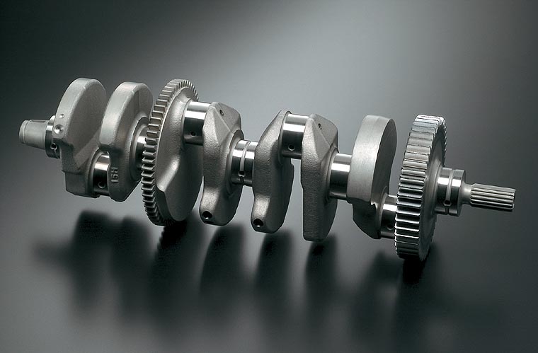
In terms of shortening the crank. Possibly replace the counterweights with drive gear like on the Yamaha crank below?

Also; are they still allowed to run radial valves? With the smaller bores and turbo cam profiles will these work well?

Image

glenntws
glenntws
87
Joined: 15 Feb 2017, 15:41
Location: Germany

Re: Honda Power Unit

Post

ncassi22 wrote:Possibly adding a valving system infront of the plug in your illustration would possibly remove the need to compromise the crown in terms of assisting swirl.... I'm speculating massively though. Maybe the actual engineers can butt in and satisfy our curiosity?
I don't think that's what's Happening because actuating this valve would cost even more space and weight. Secound: Creating a crown in the style like in the Sketch would satisfy many needs. At first, you have a Point where a part of the fuel can move appropriately to the right position to go into the pre-chamber. Second, it's really hard to achieve a high compression ratio in the chamber with such a high bore/stroke ratio. My project has a ratio of 1.13 and achieving a cr of 15:1 is already a pretty hard if you still want a "good" chamber design.

With the even higher bore/stroke ratio of ~1.51, this crown design would only make the engineers achieve their wished ratio in a easy and effective way.

Third: The Tumble in the chamber which is generated by the high angle port is already pretty high and if the crown is seperating this flow into two not so strong swirls, this wouldn't really hurt. The Flames that shootd out of the prechamber are extremely hot and fast. If the chamber is perforated enough, it allows to burn the fuel very efficiently without big swirls, which you would normally need.

But maybe Wazari will say something to it. I'm self-teaching all that to myself but I don't think I come even close to his knowledge :D

glenntws
glenntws
87
Joined: 15 Feb 2017, 15:41
Location: Germany

Re: Honda Power Unit

Post

Tommy Cookers wrote:coplanar rods save only a little length (what roon said), as modern bores are large and modern bearings are small (reason coplanars are in museums)
articulated (one coplanar type) rods will give motion differences between banks
coplanar rods will be less suited to very high rpm, but seem plausible current F1 mandated stroke and rpm used

the mandated 90 deg V could have a flat crank but still good balance, eg whole left bank firing simultaneously, then whole right
convention says rather poor for the turbo and for the crankshaft
or 1&3 left and 2 right simultaneously, then 1 & 3 right and 2 left simultaneously
which might make more sense with cylinder cutting ?

You're right with the low stability of coplanar rods. They also cause different vibrations which are hard to control at 12k rpm.

However in my opinion your idea of big bang wouldn't really work. There would simply be way to much vibrations which are simply put not really attractive in a 12k rpm engine :D

I think a possible firing order is 1-4-3-6-2-5, which allows for 90ยฐ - 150ยฐ - ... seperation in firing. This would also mean that the exhaust manifold length of each cylinder simply has to have the same length to the main connection to achieve a very static pressure flow to the turbine which in turn means a more efficient turbo.

63l8qrrfy6
63l8qrrfy6
368
Joined: 17 Feb 2016, 21:36

Re: Honda Power Unit

Post

There are several reasons why forked rods won't work, here's a couple

1. If you reduce the crank pin length then the bearing projected area will decrease - bearing pressure will go up.
2. You will get poor bearing l/d ratios and the split rod big end will always be very compliant resulting in poor ehd performance.

Chances are that even if you make the big ends work they will be so bulky that whatever you gain in torsional stiffness will be offset by the increase in inertia and your mode frequencies will remain unchanged.

A 90 deg v6 without split pins will always have uneven firing with a dominant 1.5 order as someone said earlier - alternating 90 and 150 deg firing intervals. No fancy firing orders required - these cars have 2x massive rear tires, dont think they need to recover the way bike tires do

User avatar
Wazari
623
Joined: 17 Jun 2015, 15:49

Re: Honda Power Unit

Post

You guys are really good. Mr. Glenn, you are in high school? I am impressed. When I was in high school I wasn't even thinking about ICE's, just how to get a "5" (A) on my next calculus test. Sasha-san and I have had many conversations about my particular project area and where I spent much time on piston crown design and overall piston design. Mr. Glenn you have some really brilliant ideas there.

Firing order...........hmmmmmmmmm............................

My work here is quiet at the moment. (Nice change). Two teams from here are now at Woking. Software guys are not sleeping and neither are the integration teams.
โ€œIf Honda does not race, there is no Honda.โ€

โ€œSuccess represents the 1% of your work which results from the 99% that is called failure.โ€

-- Honda Soichiro

glenntws
glenntws
87
Joined: 15 Feb 2017, 15:41
Location: Germany

Re: Honda Power Unit

Post

Wazari wrote:You guys are really good. Mr. Glenn, you are in high school? I am impressed. When I was in high school I wasn't even thinking about ICE's, just how to get a "5" (A) on my next calculus test. Sasha-san and I have had many conversations about my particular project area and where I spent much time on piston crown design and overall piston design. Mr. Glenn you have some really brilliant ideas there.

Firing order...........hmmmmmmmmm............................

My work here is quiet at the moment. (Nice change). Two teams from here are now at Woking. Software guys are not sleeping and neither are the integration teams.
Wow, this really impresses me :) Thanks for your kind words, it really means much to me if people like you give respect like this to my work.

Yeah, I think it helps if you have much fantasy, otherwise these ideas for chamber design don't come up in the head.

User avatar
PlatinumZealot
559
Joined: 12 Jun 2008, 03:45

Re: Honda Power Unit

Post

glenntws wrote:Hey guys,

I'm new in this Forum but since this discussion is very interesting, I thought I could also talk a bit with you.

First: I'm very sure the engine was running in a Controller cylinder shutoff with one cylinder active on one bank and two others on bank 2. I'm also pretty sure , the distance between the ignitions was 300ยฐ - 180ยฐ - 240ยฐ. I took a look at the sound file in audacity and here's a little part of it colored by me:

http://fs5.directupload.net/images/170215/a58lxnsu.png

The yellow colored is the ignition on bank 1, the blue and green ones are on bank 2 I think.


Second: I'm also sure that the idea of the pistons without offset won't be the right one. This way of rod design won't be good at all for the high pressures. Additionally: The crankshaft will have to have the same length either way, and a cylinder offset will only help in regards to the intake System. The 20-25mm, which they lose lose from offset cylinders won't help much at all when looking at the placement of the turbocharger.


Third: While everybody thinks that TJI will come to the Honda engine, I think I have a idea of how this System could look like. I made 4 little Sketches which could explain the System fairly good.

Intake stroke: http://fs5.directupload.net/images/170215/l9om6db6.jpg

Mid-compression stroke: http://fs5.directupload.net/images/170215/zbs2e3kp.jpg

End of compression stroke: http://fs5.directupload.net/images/170215/x3flcwfm.jpg

Start of ignition: http://fs5.directupload.net/images/170215/fq8r3ey2.jpg

Now, I will explain you why I think this should work. At first, thanks to this design, all the requirements by the fia are fullfilled.
So, once the intake stroke starts, you get a pretty high amout of tumble in the chamber, which will - because of the gas Forces - clear out the prechamber. The prechamber has a ~5mm wide opening at the bottom, which is almost completely (0.1-0.3mm distance) closed at TDC. The prechamber also has several little holes all around. which can force the ignition arcs into the main chamber.

Mid-compression stroke, the engine will start injecting fuel. Since the piston has this pinnacle at the top (which also closes the prechamber), the fuel, if it's shooted in a narrow angle onto this Point, will automatically form a rich cloud of fuel-air mixture directly under the opening of the pre-chamber. At the end of the compression stroke, this very rich cloud will partly be forced into the pre-chamber, while the main chamber will retain the two tumble motions on both sides.

When starting the combustion, the movement in the prechamber will go down with big force thanks to the droplet-replicating shape. Since the main-opening is closed, fire arcs will go into the two chamber parts and will induce a combustion in the motion of the two tumbles, which in turn will make sure the combustion will happen as clear as it can.


Keep in mind, that these sketches are made pretty fast. I just think this is a way, Honda could do it like.

I'm no Student in mechanics or thermodynaics nor do I work in this sector (finishing high school right now in Germany). However, I'm working on a engine since 2 years. While it uses HCCI, I think the (pretty big) amount of knowledge I gained could help to find out at least a little bit more about the Honda engine :)
Nice effort.

Interesting concept. But ignition would happen too late in the stroke if it needs the piston to form the nozzles for the jet.
So this would not produce the combustion at the right crank position (about 14 to 20 degrees after TDC)

Your sound files are interesting. Again good work. I am not familiar with accoustic analysis.. But could you tell me how do you know when two engine rotations have passed in your diagram? That would help us see what you are seeing.

Thanks
๐Ÿ–๏ธโœŒ๏ธโ˜๏ธ๐Ÿ‘€๐Ÿ‘Œโœ๏ธ๐ŸŽ๐Ÿ†๐Ÿ™

Racing Green in 2028

User avatar
PlatinumZealot
559
Joined: 12 Jun 2008, 03:45

Re: Honda Power Unit

Post

Tommy Cookers wrote:coplanar rods save only a little length (what roon said), as modern bores are large and modern bearings are small (reason coplanars are in museums)
articulated (one coplanar type) rods will give motion differences between banks
coplanar rods will be less suited to very high rpm, but seem plausible current F1 mandated stroke and rpm used
early V8s etc used existing 4 cylinder flat cranks so coplanar rods were needed, side-by-side rods came after the crossplane crank emerged ?

EDITED to clarify dramatic intent ......
mandated 90 deg V could have (with balance unimpaired) eg all the throws at 0 deg, allowing eg whole left bank firing simultaneously, then whole right
convention says this would be rather poor for the turbo and for the crankshaft
or 1&3 left and 2 right simultaneously, then 1 & 3 right and 2 left simultaneously
which might make some sense with cylinder cutting ?
that is a huge wait before the next round of firing though. It would be like two one cylinder engines firing out of sync. If they were in big bang mode. Not good for the turbo as you said. Nasty vibrations would spell hell for reliability i think.

I supposed they stick to split journals. To make the engines fire evenly to get best smoothness. (15 degree offset on each solit journal).
๐Ÿ–๏ธโœŒ๏ธโ˜๏ธ๐Ÿ‘€๐Ÿ‘Œโœ๏ธ๐ŸŽ๐Ÿ†๐Ÿ™

Racing Green in 2028

User avatar
godlameroso
309
Joined: 16 Jan 2010, 21:27
Location: Miami FL

Re: Honda Power Unit

Post

glenntws wrote:
Wazari wrote:You guys are really good. Mr. Glenn, you are in high school? I am impressed. When I was in high school I wasn't even thinking about ICE's, just how to get a "5" (A) on my next calculus test. Sasha-san and I have had many conversations about my particular project area and where I spent much time on piston crown design and overall piston design. Mr. Glenn you have some really brilliant ideas there.

Firing order...........hmmmmmmmmm............................

My work here is quiet at the moment. (Nice change). Two teams from here are now at Woking. Software guys are not sleeping and neither are the integration teams.
Wow, this really impresses me :) Thanks for your kind words, it really means much to me if people like you give respect like this to my work.

Yeah, I think it helps if you have much fantasy, otherwise these ideas for chamber design don't come up in the head.
Your drawing made me think about something Wazari said about hypthetical ports on the piston crown. What if the piston crown forms part of the pre-chamber(ie the raised section cups the spark plug), and the raised section has perforations to create the flame jets? With clever valving you could very precisely control how much combustion happens inside and outside the pre-chamber. Maybe with multiple injections and sparks, all precisely timed a much leaner burn can be achieved. For example a small squirt on the piston upstroke to create a rich enough environment in the pre-chamber, and another tiny squirt near TDC to create a rich enough environment in the main chamber, and maybe one more timed immediately after TDC which would auto ignite due to the flame jets.
Saishลซ kลnฤ

User avatar
PlatinumZealot
559
Joined: 12 Jun 2008, 03:45

Re: Honda Power Unit

Post

Spark plugs can be changed regularly without penalty right?
A problem of TJI spark plug nozzles when used with petrol is soot blocking them up.
So i supposed a lot of energy is spent on preventing soot formation.
๐Ÿ–๏ธโœŒ๏ธโ˜๏ธ๐Ÿ‘€๐Ÿ‘Œโœ๏ธ๐ŸŽ๐Ÿ†๐Ÿ™

Racing Green in 2028