2 stroke thread (with occasional F1 relevance!)

All that has to do with the power train, gearbox, clutch, fuels and lubricants, etc. Generally the mechanical side of Formula One.
J.A.W.
J.A.W.
109
Joined: 01 Sep 2014, 05:10
Location: Altair IV.

Re: 2 stroke thread (with occasional F1 relevance!)

Post

This archaic Brit 2T unit - interestingly - utilizes a crank flywheel - as a 3D rotary valve..

http://www.villiers.info/Alpha/index.htm
"Well, we knocked the bastard off!"

Ed Hilary on being 1st to top Mt Everest,
(& 1st to do a surface traverse across Antarctica,
in good Kiwi style - riding a Massey Ferguson farm
tractor - with a few extemporised mod's to hack the task).

manolis
manolis
107
Joined: 18 Mar 2014, 10:00

Re: 2 stroke thread (with occasional F1 relevance!)

Post

Hello Mudflap

You write:
“The ideal combustion chamber is whatever offers the largest flame front area, fastest burn rate and minimal flame-wall contact. Heywood specifically states that a disc shaped chamber (rectangular cross section) where the flame initiates from the side is the worst in terms of combustion speed.”


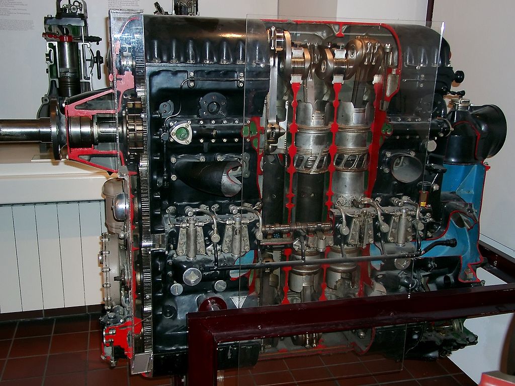
According Heywood, the Junkers JUMO 205 (first run: 1930) with the “disk shaped chamber where the flame initiates from the side”:

Image

should not run as it did / does:


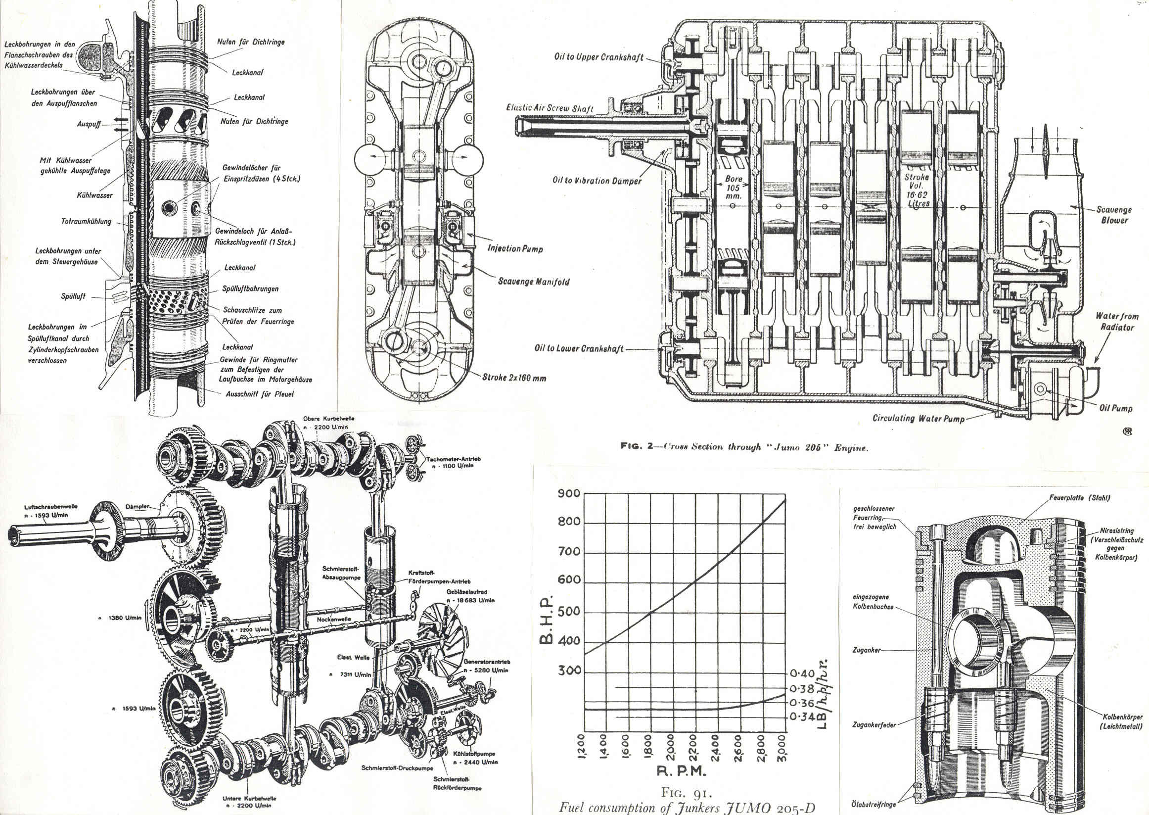
The BSFC plot (bottom middle):

Image

shows a 0.35lb/hp/hr (i.e. 216gr/kWh, which means a Brake Thermal Efficiency (BTE) of 37.5%).

(click http://www.pattakon.com/tempman/Junkers ... 5_BSFC.jpg if the drawing is not clear).


The peak injection pressure is only 600 bar.

The design is old (more than 80 year old).

The 37.5% BTE is maintained in a wide range of revs (from 1,500 to 2,500).

The 37.5% is not the peak BTE of the engine.

The fuel efficient, lightweight and reliable Junkers Jumo Diesels enabled, for the first time, airplanes to travel at distances not possible before.


So,
either Heywood is not right, or the rest characteristics of the Opposed Piston Jumo 205 are by far superior than those of the state-of-the-art modern Diesels (wherein the flame initiates centrally, wherein the fuel is injected at way higher pressures (fine droplets) and with the perfect timing, wherein everything is optimized by computers, etc, etc) to justify the 37.5% “working” BTE .


Now, take the Junkers Jumo 205 and modify it to PatOP or to OPRE.

Use either the centrifugal compressor of the Junkers Jumo 205 as scavenging pump, or, preferably, a turbocharger driven by the exhaust gas.

The lube specific consumption drops a few times and the frictional losses reduce (cross-head architecture, true hydrodynamic lubrication whereon the thrust loads are taken and the torque is created.

The time provided for the combustion increases by, say, 30% due to the longer dwell of the piston at the combustion dead center (this is an advantage the pulling-rod architecture offers):

Image

Image


Partly QUOTE from http://www.pattakon.com/pattakonOPRE2.htm

Fuel's Viewpoint

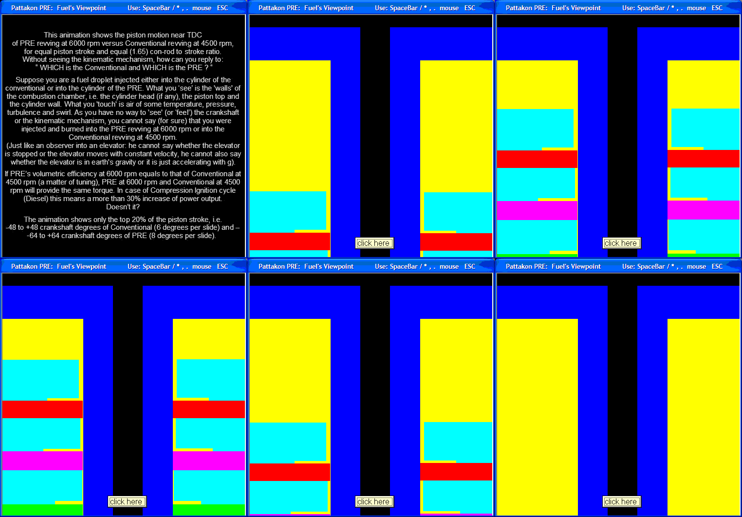
The following animation shows the piston motion near TDC of an OPRE or PatOP engine revving at 6000 rpm versus a Conventional engine revving at 4500 rpm, for equal piston stroke and equal (1.65) con-rod to stroke ratio.

Without seeing the kinematic mechanism, how can you reply to: " WHICH is the Conventional and WHICH is the PRE ? "

Suppose you are a fuel droplet injected either into the cylinder of the conventional or into the cylinder of the OPRE / PatOP.
What you 'see' is the 'walls' of the combustion chamber, i.e. the cylinder head (if any), the piston top and the cylinder wall.
What you 'touch' is air of some temperature, pressure, turbulence and swirl.
As you have no way to 'see' (or 'feel') the crankshaft or the kinematic mechanism, you cannot say (for sure) that you were injected and burned into the OPRE / PatOP revving at 6000 rpm or into the conventional revving at only 4,500rpm.

Among others, this means that the rev limit of the Diesels (and their peak power) can rise by some 30%

Image

End of QUOTE

A pulling connecting rod is way stronger for the loads it bears (so it can substantially more lightweight) than a conventional connecting rod. The heavy loads in the OPRE / PatOP try to strengthen the connecting rods.

The engine gets shorter and more lightweight:
The PatOP prototype (64+64=128mm stroke, 79.5mm bore, 636cc capacity, 850cc built-in scavenging pump capacity, total mass (without the flywheel) 20kg, total height: 500mm)

Etc.


You also write:
“Sure, Achates have blown 100 million on testing and simulation - it only makes sense that they have managed to develop a very efficient engine. But what is to say that your engine will have similar performance - just the fact that it too uses opposed pistons ?”


In the previous (and at http://www.pattakon.com/pattakonOPRE.htm and http://www.pattakon.com/pattakonPatOP.htm ) is explained the superiority of the OPRE and PatOP designs over the conventional Junkers Jumo.


What is the current offer / product of the Achates Power?


https://www.youtube.com/watch?v=JoQkTIfAB2U

What I see in the above youtube video is a redesigned Junkers Jumo 205 with reasonable / expected improvements:
better flow capacity,
optimized combustion chamber shape,
modern fuel injection,
better/modern control over the engine (electronic control versus mechanical control).

It is like giving to a good tuner an 85year old Junkers Jumo 205 and ask him to improve / modernize / redesign it from scratch (and in a “no budget” basis).

Different tuners will follow different ways / solutions.

For instance, the shape of the combustion chamber formed in/on the piston crowns of the Achates Power engines is not the only shape that improves the combustion.

For instance, the market is full of injectors / injection systems / electronic controllers that can be used in an improved Junkers Jumo 205.


The several dozens of millions of dollars invested so far to the Achates Power Opposed Piston engine projects is a good evidence that we, at pattakon, are not the only ones who think there is a promising future for the Opposed Piston engines.


So, if Achates Power really achieved the fuel efficiency they claim, this is more than good for the PatOP and OPRE engines.

It is not difficult to get why.

For instance, what if Achates Power asks to use, under the license of pattakon, the PatOP / OPRE design? With a better “basis engine” than the Junkers Jumo, their final product would be better.

Or, for instance, what Achates Power is asked to offer (under license) their technology for use in the OPRE and PatOP engines?


Thanks
Manolis Pattakos

manolis
manolis
107
Joined: 18 Mar 2014, 10:00

Re: 2 stroke thread (with occasional F1 relevance!)

Post

Hello J.A.W.

You write:
“This archaic Brit 2T unit - interestingly - utilizes a crank flywheel - as a 3D rotary valve..
http://www.villiers.info/Alpha/index.htm


Nice link and story.

The crankshaft with the “disk / cylindrical /drum” valve of the two-cylinder Alpha 250cc Centuri, is shown, but not too clearly. I suppose it is made of two independent crankshafts secured on the “disk” valve at the centrer.


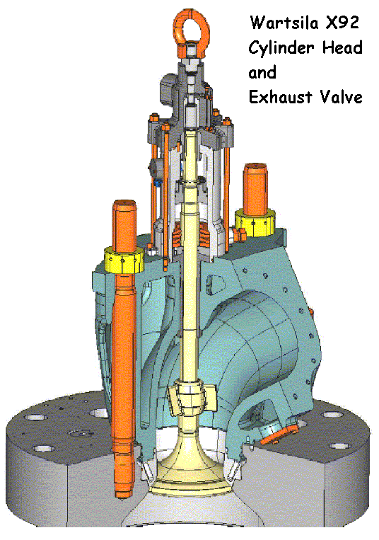
Here is the cylinder head / exhaust valve of the giant Wartsila X92 marine 2-stroke:

Image


Talking for rotary valves, imagine replacing the above exhaust poppet valve by a PatRoVa rotary exhaust valve:

Image

driven by an electric step-motor (offering flexibility- variability – precision – simplicity).

The height of the engine (which is a significant limitation for such size engines) lowers by 1.5m or so.

Thanks
Manolis Pattakos

Tommy Cookers
Tommy Cookers
646
Joined: 17 Feb 2012, 16:55

Re: 2 stroke thread (with occasional F1 relevance!)

Post

afaik the speed of a CI engine can be no greater than allowed by the inevitable combustion delay characteristic of the fuel ?

the SI aero engine of course made the CI aero engine look pointless after the rapid improvement of aviation gasoline quality
though the 2 stroke CI KHD Dz 710 c.1944 conventional flat 16 at about 3200 lb/2700 hp and 0.33 lb/hp-hr sfc was plausible
actuals were 2360 hp and 0.34 lb
https://oldmachinepress.com/2013/08/17/ ... nd-dz-720/

Wright's SI 0.38 lb sfc engines had a CR of only 6.5, this bte on Avgas corresponds to 0.355 lb sfc in a CI engine
the efficiency of the Nomad was identical to Wright's
but SI aero engines configured only for cruise efficiency could have used a CR of 10 or 11
large SI engines used on land or sea in WW2 used 80 octane fuel but normal CR eg the NA version of the Merlin used a CR of 8


btw it's Alpha Centauri (same as the star) - not Centuri
Last edited by Tommy Cookers on 28 Apr 2017, 14:00, edited 3 times in total.

J.A.W.
J.A.W.
109
Joined: 01 Sep 2014, 05:10
Location: Altair IV.

Re: 2 stroke thread (with occasional F1 relevance!)

Post

manolis wrote:
28 Apr 2017, 09:39
Hello J.A.W.

You write:
“This archaic Brit 2T unit - interestingly - utilizes a crank flywheel - as a 3D rotary valve..
http://www.villiers.info/Alpha/index.htm


Nice link and story.

The crankshaft with the “disk / cylindrical /drum” valve of the two-cylinder Alpha 250cc Centuri, is shown, but not too clearly. I suppose it is made of two independent crankshafts secured on the “disk” valve at the centre.

Thanks
Manolis Pattakos

Hi Manolis,
yes - the poppet valve might well be replaced by the advent of something better, as you suggest..

As for the Villiers based twin, it is a bit hard to tell, so perhaps it was using a 360`crank (a 'twingle')..
..thus enabling both cylinders to share the single inlet system?
"Well, we knocked the bastard off!"

Ed Hilary on being 1st to top Mt Everest,
(& 1st to do a surface traverse across Antarctica,
in good Kiwi style - riding a Massey Ferguson farm
tractor - with a few extemporised mod's to hack the task).

Pinger
Pinger
9
Joined: 13 Apr 2017, 17:28

Re: 2 stroke thread (with occasional F1 relevance!)

Post

J.A.W. wrote:
28 Apr 2017, 12:46


As for the Villiers based twin, it is a bit hard to tell, so perhaps it was using a 360`crank (a 'twingle')..
..thus enabling both cylinders to share the single inlet system?
Is this:

''As the disc controlled inlet periods of less than 180 degrees, this system was deemed as perfectly satisfactory for the state of tune prevailing some thirty years ago. With modern high performance engines having an inlet period of truly wild proportions, this system would not be adequate, and a change to twin carburetors would have been required.''

not the clue to 180 degree crank?

edit PS.
Carb size also. A 29mm Dell Orto which was downsized by only 1mm for the single cylinder 125.
Last edited by Pinger on 28 Apr 2017, 13:49, edited 1 time in total.

Tommy Cookers
Tommy Cookers
646
Joined: 17 Feb 2012, 16:55

Re: 2 stroke thread (with occasional F1 relevance!)

Post

the illustrational drawing at the end shows a 180 deg crank, judging by the angles of the 2 rods

manolis
manolis
107
Joined: 18 Mar 2014, 10:00

Re: 2 stroke thread (with occasional F1 relevance!)

Post

Hello Mudflap

You write:
“Piston skirts as well as compression rings in conventional pistons also operate in a hydrodynamic regime except during reversals (but then the same happens for crossheads too). And guess what - if you have a look at a Striebek curve you'll find that the coefficient of friction is minimal during mixed lubrication and steadily increases as you go further into the hydrodynamic regime. Your argument regarding the elimination of frictional losses is invalid. You are just moving the forces from the skirt to the crosshead.”


So, the cross-head design and the hydrodynamic lubrication increase the frictional loss!


Write to Wartsila and MAN (the two makers of giant marine two-stroke engines) to explain the annual saving in case they will eliminate the cross-head and ask a percentage of this saving.

I am joking.

On the other hand, did you see the leaning angle of the connecting rod of the Wartsila X92?

It is from -30 to +30 degrees about the cylinder axis.

A conventional engine having the double connecting rod to stroke ratio (2:1 instead of 1:1 of the Wartsila X92) halves the thrust load between the piston skirt and the cylinder liner.

According what you write, the Wartsila X92 with double thrust force and higher coefficient of friction (it utilises the “inefficient” hydrodynamic lubrication instead of the “efficient” mixed lubrication) should have more than double frictional losses due to the leaning of the connecting rod.
We talk for the most efficient engines in the world (the giant marine 2-strokes).


For decades in Ducati they were using expensive angular contact roller bearings to rotatably mount their crankshafts in their crankcases for the sake of, supposedly, lower friction and higher revving (the roller bearing makers give these roller bearings as heaving 0.002 coefficient of friction).

Then they replaced the angular contact roller bearings with conventional plain bearings:

Quote from CycleWorld:

Image

The new plain bearings versus the old 35/80/21 angular contact ball bearings. The plain bearings bring significant advantages in load capacity, mechanical quietness and additional crankshaft rigidity. They also save money in production. The main-end plain bearings do not feature the usual groove and admission hole because Taglioni has always favored axial admission lubrication circuits, which require less pressure. With axial admission, the oil flow does not need to overcome the centrifugal force found in a radial admission layout.

End of QUOTE


The hydrodynamically lubricated plain bearings have a coefficient of friction similar to the coefficient of friction of the cylindrical roller bearings (in the range of 0.001).

With hydrodynamic lubrication the coefficient of friction of the cross-head is similar.
The lubricant is provided under pressure between the flat slides (or slippers) and the flat slideways of the cross head.
It is a forced lubrication (not the “splash” lubrication of the conventional “trunk piston” engines wherein, among others, the cylinder liner undergoes significant deformation).
And it has to do with flat surfaces that perfectly fit with each other.
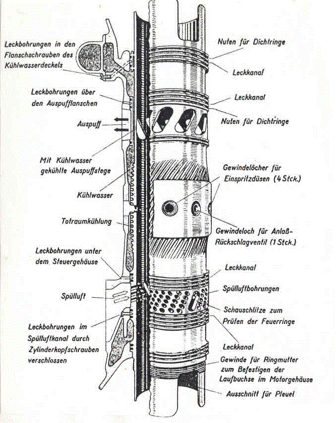
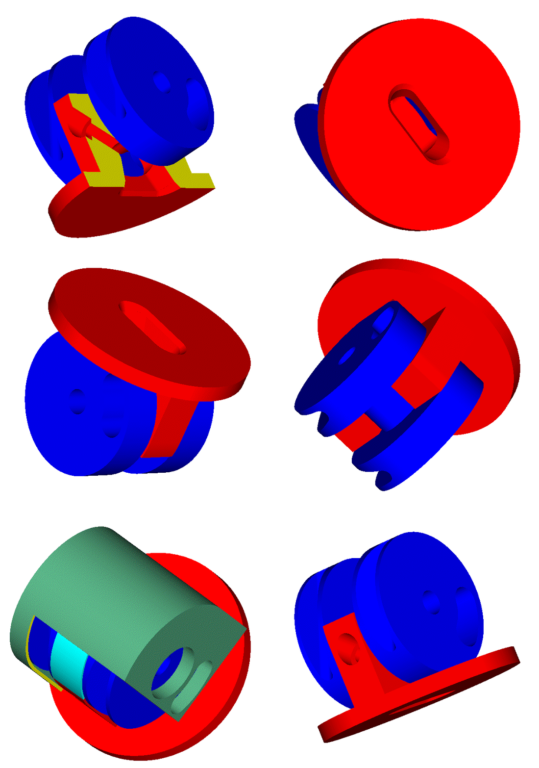
This allows the makers of the top fuel efficient internal combustion engines of the world (which, by the way, are burning cheap “heavy fuel oil”) to play with very short connecting rods, not possible in conventional “trunk piston” engines.


I would really appreciate if you could describe the situation met in the conventional 2-strokes (like, say, in the Junkers Jumo of Achates Power, or in the Junkers Doxford (or OPOC) of EcoMotors ) wherein the piston skirts abuts heavily on the ported cylinder liner.
Things are even worse at the exhaust side.
What happens there with the lubricant?
Shortage of lubricant means scuffing.
Plenty of lubricant means emissions, worse combustion and lubricant consumption.

With the cross head architecture of the OPRE and PatOP engines, only a thin film of lubricant is required to prevent the contact of the piston rings with the cylinder liner.


Thanks
Manolis Pattakos

manolis
manolis
107
Joined: 18 Mar 2014, 10:00

Re: 2 stroke thread (with occasional F1 relevance!)

Post

Hello Tomy Cookers

You write:
“afaik the speed of a CI engine can be no greater than allowed by the inevitable combustion delay characteristic of the fuel ?”


Exactly.

Even with the best Diesel fuel, the power of the conventional CI engines cannot help dropping steeply after 4,000 or 4,500rpm.

What the OPRE and the PatOP (pulling rod architecture) offer?

Time.

Additional time.


The piston remains at the top of its stroke (say, at the top 10% of its stroke) for some 30% longer time.

This way the fuel “feels” like being injected / burned inside a conventional revving at 30%, or so, slower revs.

Only few people really understand this significant characteristic of the “pulling rod” architecture.

[video]http://www.pattakon.com/pre/OPRE3.MOV[/video]


https://www.youtube.com/watch?v=Xd0A0yyC7DU

Put together the cross head design and the resulting several times lower lube specific consumption, as well as the additional time offered by the pulling rods (which translates into substantially higher power for the CI engines).

These advantages alone (there are more) justify the superiority of the OPRE and PatOP engines over the Achates Power and Ecomotors OPOC opposed piston engines.


Thanks
Manolis Pattakos

J.A.W.
J.A.W.
109
Joined: 01 Sep 2014, 05:10
Location: Altair IV.

Re: 2 stroke thread (with occasional F1 relevance!)

Post

Pinger wrote:
28 Apr 2017, 12:58
J.A.W. wrote:
28 Apr 2017, 12:46


As for the Villiers based twin, it is a bit hard to tell, so perhaps it was using a 360`crank (a 'twingle')..
..thus enabling both cylinders to share the single inlet system?
Is this:

''As the disc controlled inlet periods of less than 180 degrees, this system was deemed as perfectly satisfactory for the state of tune prevailing some thirty years ago. With modern high performance engines having an inlet period of truly wild proportions, this system would not be adequate, and a change to twin carburetors would have been required.''

not the clue to 180 degree crank?

edit PS.
Carb size also. A 29mm Dell Orto which was downsized by only 1mm for the single cylinder 125.
Ta for that P & T-C, & here is an example of a 'twingle' ( 360`crank/twin-fire 2T);
http://www.motorcycleclassics.com/class ... mz16ndzhur

This was a doubled-up OSSA 250 single, & a couple of those were also doubled-up - to make a 1000/4..
"Well, we knocked the bastard off!"

Ed Hilary on being 1st to top Mt Everest,
(& 1st to do a surface traverse across Antarctica,
in good Kiwi style - riding a Massey Ferguson farm
tractor - with a few extemporised mod's to hack the task).

63l8qrrfy6
63l8qrrfy6
368
Joined: 17 Feb 2016, 21:36

Re: 2 stroke thread (with occasional F1 relevance!)

Post

Oh wow - I might struggle to keep up with you two ! - I'll give it a go.
gruntguru wrote:
28 Apr 2017, 01:37
You must be reading the section on spark ignition. These are Diesel engines. Regardless, if you look at the Pat OP above you will see the combustion chamber (at TDC) is anything but a pancake.
You are correct - that was for a petrol engine. Unfortunately there is not a similar chapter for diesels. Surely the principles I have mentioned must be the same though ?

While it is not exactly pancake shaped - it has an arbitrarily shaped bowl. Can't just point at it and say 'that's where the ultimate combustion happens' right ?

Which is a key benefit of the cross-head design.
1. Elimination of tilting of the piston improves efficiency of all the rings allowing reduced ring tension and reduced lubrication.

Not exactly. Piston secondary motion has little effect on ring performance. For all practical purposes the rings can be assumed to only react piston forces along the bore centreline. The circumferential gradient of ring pressure is also assumed to be 0. In Manolis' design there will still be a small amount of radial motion due to the clearances in the sliders - maybe it is a bit smaller than for a conventional piston but realistically it will not have a measurable effect.

As for reducing ring tension - do not forget that the main purpose of the rings is to seal the combustion pressure. Tension is there to prevent radial collapse. Maybe the oil ring spring load can be reduced a bit but I am not convinced. At the end of the day you still have 2x sliders, 3x big end bearings and 2 sets of rings where 1 piston with 1 small end and 1 big end would have sufficed. I choose to completely ignore arguments of the type 'X has thrown 100 millions at it and made it work'. Where I work we design very successful racing engines for just over a tenth of that. With that much money you should be able to fly a lawn mower engine to the moon.

Anyway, back to piston rings: One of the big disadvantages of liner ports is the high amplitude high order distortion of the bore. The shape filling capacity of the ring is inversely proportional with the 4th power of the order of distortion. In a conventional engine, the dominant distortion order is more or less the number of head bolts and its amplitude is quite low. In a liner full of 'holes' the order will be much higher and the amplitudes larger - that is to say they will be rubbish at sealing. I am trying to keep this post reasonably short - if you want any further details on the physics/ maths I will be more than happy to share.


2. Eliminating the skirt as a cross-head bearing further reduces the quantity of oil required on the bore.

Again, not too sure about this.. oil will still be required to lubricate the rings and I assume a fair bit will also be used to cool the pistons. And as I have mentioned before there's the issue of oil pooling in the upside down piston.
I am sure this is not a deliberate attempt to mislead and you simply overlooked the fact that the extra piston contributes its own displacement, so oil consumption as a function of engine displacement remains the same were you to substitute the opposing piston with a cylinder head.
A cylinder head that leaks oil, yes.
A pulling connecting rod is way stronger for the loads it bears (so it can substantially more lightweight) than a conventional connecting rod. The heavy loads in the OPRE / PatOP try to strengthen the connecting rods.
I re-read this several times and it did not make sense once. I'll give you the benefit of the doubt and put it down to the language barrier.
So, the cross-head design and the hydrodynamic lubrication increase the frictional loss!
That's not what I said. I said the losses are about the same. You said there are no losses at all which is plainly wrong.
The hydrodynamically lubricated plain bearings have a coefficient of friction similar to the coefficient of friction of the cylindrical roller bearings (in the range of 0.001).

With hydrodynamic lubrication the coefficient of friction of the cross-head is similar.
The lubricant is provided under pressure between the flat slides (or slippers) and the flat slideways of the cross head.
It is a forced lubrication (not the “splash” lubrication of the conventional “trunk piston” engines wherein, among others, the cylinder liner undergoes significant deformation).
And it has to do with flat surfaces that perfectly fit with each other.
While I agree that journal bearings can be optimized to achieve similar power losses to roller bearings - this can only be done reliably for steady-state operation. When a journal bearing operates very close to the mixed lubrication boundary it is very unstable thermally, meaning a momentarily increase in friction can cascade into an increase in temperature which lowers the viscosity, which in turn increases friction even more, etc - resulting in rapid failure.

Finally - if you have 'flat surfaces that perfectly fit with each other' (machined by NASA presumably) you will not get a hydrodynamic film ! 2 perfectly flat surfaces moving in parallel in oil will only generate a shear force (which opposes motion). In order to generate a hydrodynamic film the surfaces have to either move towards each other (squish) or not be parallel (yet move in parallel directions) aka the wedge effect.

Pinger
Pinger
9
Joined: 13 Apr 2017, 17:28

Re: 2 stroke thread (with occasional F1 relevance!)

Post

Re plain vs roller bearings. The losses accrued from pumping the oil to plain bearings cannot easily be overlooked. If there was no benefit from roller bearings, then doubtful if OEM would be adopting them for camshafts etc. I think Porsche recently patented a built up crank assembly method to enable roller bearings to be used. Also - though happy to be proved wrong - I cannot recall an engine started only by kick (or pull) starter ever having plain bearings (other than splash lubed side valve donkey engines).

In the last bout of F1 engines (NA screamers) were the piston rings dispensed with entirely? (Always wondered given the interference piston fit in the bore).

manolis
manolis
107
Joined: 18 Mar 2014, 10:00

Re: 2 stroke thread (with occasional F1 relevance!)

Post

Hello Mudflap

You write:
“Oh wow - I might struggle to keep up with you two ! - I'll give it a go”

! . . .


You also write:
“Anyway, back to piston rings: One of the big disadvantages of liner ports is the high amplitude high order distortion of the bore. The shape filling capacity of the ring is inversely proportional with the 4th power of the order of distortion. In a conventional engine, the dominant distortion order is more or less the number of head bolts and its amplitude is quite low. In a liner full of 'holes' the order will be much higher and the amplitudes larger - that is to say they will be rubbish at sealing. I am trying to keep this post reasonably short - if you want any further details on the physics/ maths I will be more than happy to share.”


Here is a “full of holes” liner of the Junkers Jumo 205:

Image

And it is anything but “rubbish at sealing”.

This is a more than 80 years old design / manufacturing.

17:1 compression ratio, compression ignition.

If it had problematic sealing, or not top fuel efficiency, it would not be used in airplanes making (for the first time; 1936) 6,000 miles without a stop.


Your theory relating the “sealing efficiency” with the number of holes / ports on the cylinder liner needs amendments.


For instance, a cylinder liner having a wide exhaust port at one side, and a number of transfer ports around the cylinder has many reasons to deform and spoil the sealing.

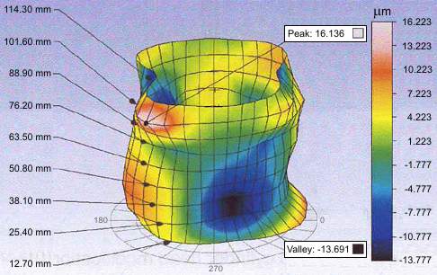
Also a cylinder liner whereon the piston skirt thrusts heavily, or a cylinder tighten to a cylinder head by bolts, have good reasons to deform and spoil the sealing and the lubrication:

Image

The thrust of the piston skirt on specific regions at the sides of the cylinder liner spoils the shape of the cylinder liner and makes the temperature distribution around the cylinder liner uneven (this unevenness is further increased by the non uniform arrangement of the intake and exhaust valves on the cylinder head).

A cylinder head integral with the cylinder is a good solution (Bishop rotary valve F1 engine uses this method, and besides avoiding the gasket and improving the cooling, it also reduces the overall weight of the engine).

Another good solution is the approach of Hugo Junkers with his twin crankshaft Opposed Piston Jumo engines wherein the intake ports, at the one end of the cylinder liner, and the exhaust ports, at the other end of the cylinder, are too many and uniformly distributed. Only the thrust loads on the sides of the cylinder liner spoil the – otherwise perfect – cylindrical symmetry of load distribution, temperature distribution, etc.


A far better solution is the OPRE and PatOP “cross head” architecture where the cylinder liner is, among others, completely rid of thrust loads.
The cylindrical symmetry of loads and of temperatures gets perfect.
The high gas pressure during compression – combustion – expansion is the only load the cylinder liner bears (the thrust loads are taken by the cross-head, away from the cylinder liner).
Can you think a more symmetrical load for a thin walled cylinder?
The temperature varies along the axis of the cylinder liner (hotter at the exhaust side, colder at the intake side), however the temperature around any “cut” of the cylinder liner normal to the cylinder axis is constant.
All the previous are ideal for the cooperation of the piston rings with the cylinder liner (improved sealing).


So, think again.


You also write:
“I re-read this :

(A pulling connecting rod is way stronger for the loads it bears (so it can substantially more lightweight) than a conventional connecting rod. The heavy loads in the OPRE / PatOP try to strengthen the connecting rods.)

several times and it did not make sense once. I'll give you the benefit of the doubt and put it down to the language barrier.”


So, let me use the international language (the language of images).


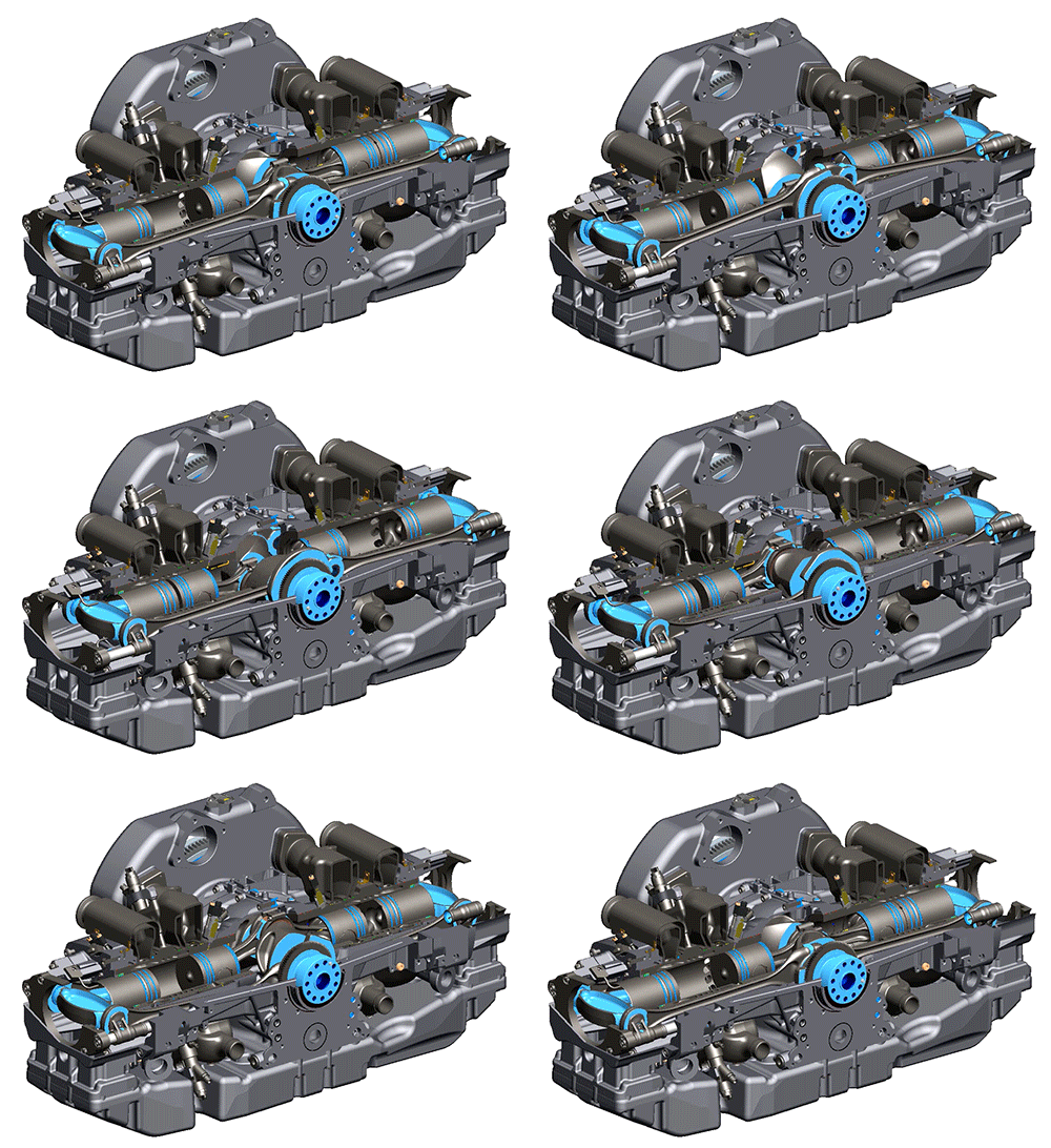
Here is an expanatory animation made by EcoMotors:

Image

Look at the slim – long “side” connecting rods of the OPOC.

They survive only because the heavy loading is in tension.

The column loading is several times weaker.


You also write:
“So, the cross-head design and the hydrodynamic lubrication increase the frictional loss!

That's not what I said. I said the losses are about the same. You said there are no losses at all which is plainly wrong.”


However, and according what you wrote, the giant 2-strokes with the extremely short connecting rods should have more than double frictional losses due to the extreme leaning of their connecting rods, which is wrong.

The hydrodynamic lubrication in the cross head is so superior than the lubrication between the piston skirt and the cylinder liner, that reduces several times the friction loss due to the leaning of the con-rod.

The coefficient of friction in a cross-head is comparable with the coefficient of friction in the plain bearings (around 0.001).


.

You also write:
“Finally - if you have 'flat surfaces that perfectly fit with each other' (machined by NASA presumably) you will not get a hydrodynamic film ! 2 perfectly flat surfaces moving in parallel in oil will only generate a shear force (which opposes motion). In order to generate a hydrodynamic film the surfaces have to either move towards each other (squish) or not be parallel (yet move in parallel directions) aka the wedge effect.”


If you compare the fitting of a piston skirt with the distorted cylinder:

Image

then you may agree that, in comparison, the flat surfaces of the cross head fit perfectly.

And this doesn’t mean that the cooperating flat surfaces of the cross-head run absolutely parallel.

The piston-skirt / cylinder-liner clearance and the clearance between the sliders and the slide-ways of the cross-head allow them the required tiny leaning.


By the way, I am waiting for your “description” of what is happening with the lubricant when the piston abuts heavily on, and slides along, the port openings of a 2-stroke.


Thanks
Manolis Pattakos

J.A.W.
J.A.W.
109
Joined: 01 Sep 2014, 05:10
Location: Altair IV.

Re: 2 stroke thread (with occasional F1 relevance!)

Post

Pinger wrote:
29 Apr 2017, 09:14
Re plain vs roller bearings. The losses accrued from pumping the oil to plain bearings cannot easily be overlooked. If there was no benefit from roller bearings, then doubtful if OEM would be adopting them for camshafts etc. I think Porsche recently patented a built up crank assembly method to enable roller bearings to be used. Also - though happy to be proved wrong - I cannot recall an engine started only by kick (or pull) starter ever having plain bearings (other than splash lubed side valve donkey engines).
Cheapo 2T utility engines such as domestic lawn-mowers commonly featured plain big-ends..

& many old Brit machines combined plain bearing big-ends ( often running on the Al-alloy conrod sans shells)..
..with rolling element main bearings.. ..albeit..
..notoriously parsimonious BSA/Triumph boss Edward Turner even cheaped out & used a plain bush..
..on the 'less heavily stressed' timing side main of certain machines, to lasting opprobrium..
.. & Kawasaki did fit an all rolling element bottom end on their BSA A10 reiteration..

Honda introduced all plain bearings in its high-production run CB 750/4, for cost reasons, though many
Honda owners later found their machines with cams running in the head casting sans shells, annoying..
..for reconditioning..

The oil-cooling function of liberally pumped quantities of oil is one 'benefit' of the plain bearing unit,
I can recall riding an Fe top-end H-D Sportster (rolling element/low pressure) in 40`ambient, & felt
some 'mechanical sympathy' for the wheezing, pinging, oil weeper, -'til it burned my leg on its oil tank..
"Well, we knocked the bastard off!"

Ed Hilary on being 1st to top Mt Everest,
(& 1st to do a surface traverse across Antarctica,
in good Kiwi style - riding a Massey Ferguson farm
tractor - with a few extemporised mod's to hack the task).

manolis
manolis
107
Joined: 18 Mar 2014, 10:00

Re: 2 stroke thread (with occasional F1 relevance!)

Post

Hello Pinger.

The Ducati Panigale Superleggera 1299 (cost: £72,000) has one of the most expensive, most extreme and most technologically advanced engines today.

Image

Its crankshaft has one only crankpin (which means: the main bearings can easily be roller bearings with “singe piece” crankshaft).

For many decades in Ducati they were using roller bearings to rotatably mount the crankshaft into the crancase.

Now Ducati uses plain bearings for their top model, and they seem more than satisfied.

Thanks
Manolis Pattakos