You write:
“Another way of dealing with such concerns could be with a horizontal-3D semi dome shaped rotary valve seated above,
& opening a port directly into the combustion chamber, delivering a timed pressure charged swirl/vortex input.
& once the piston had swept up past the exhaust port.. after the cylinder had duly accepted the sonic pulse from its tuned exhaust chamber, ( any turbo being situated downstream from the pulse chamber).
A variable-tuned sonic nozzle-type exhaust could function as the 'throttle'.. along with variable pulsed fuel injection .”
But then, the simplicity of the 2-stroke is gone.
You also write:
“Perhaps visualized as similar to the diagram shown here: https://www.pureburnengines.co.uk/two-s ... pplication
but with the added 'active' valving on inlet & exhaust which predicate flow control.”
I think Evinrude E-TEC G2:

does the same without “doubling” the surface of the cylinder walls.
You also write:
”This would also allow the choice of a typical crankcase scavenged 2T, plus turbo, -for smaller units.
.. or a '4T type' plain-bearing bottom-end with compound compressor/turbo - for larger machines..”
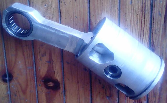
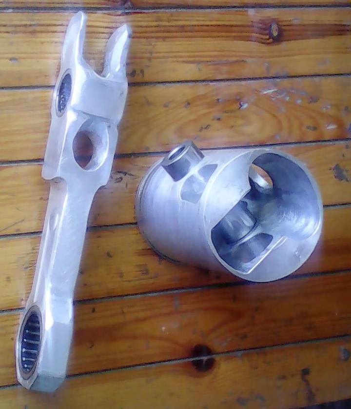
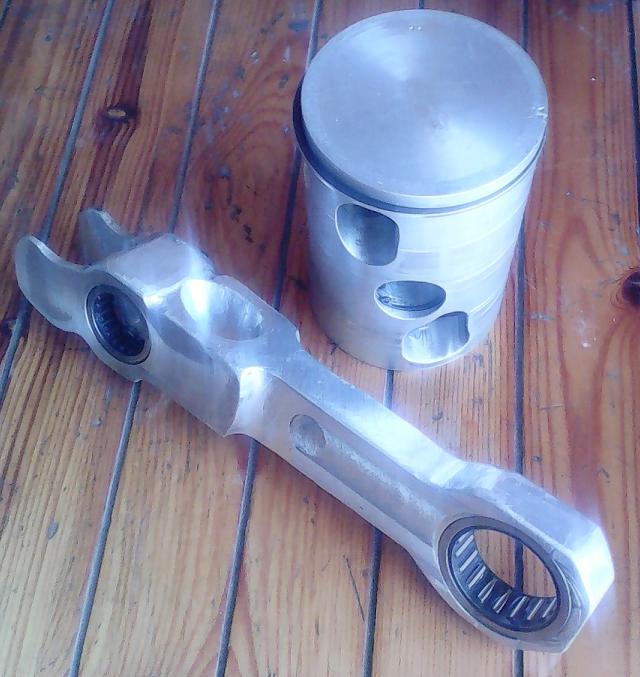
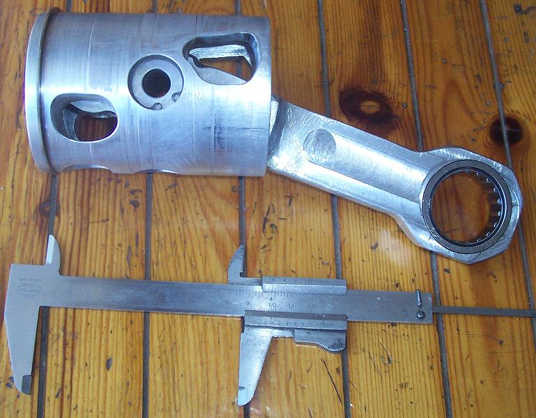
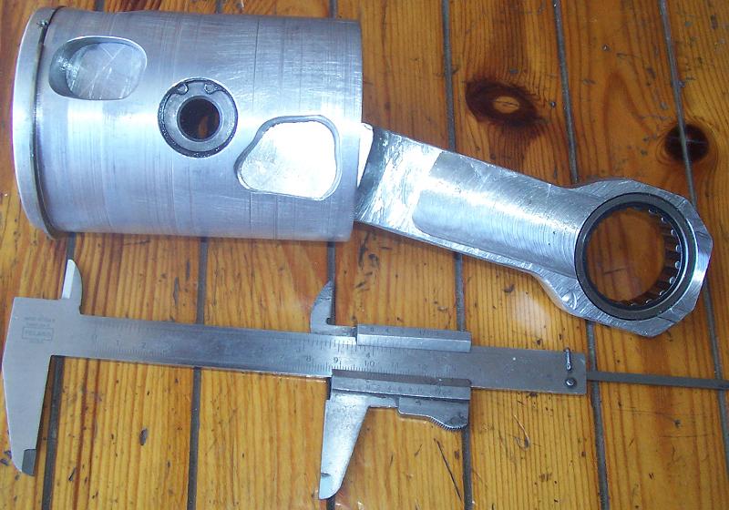
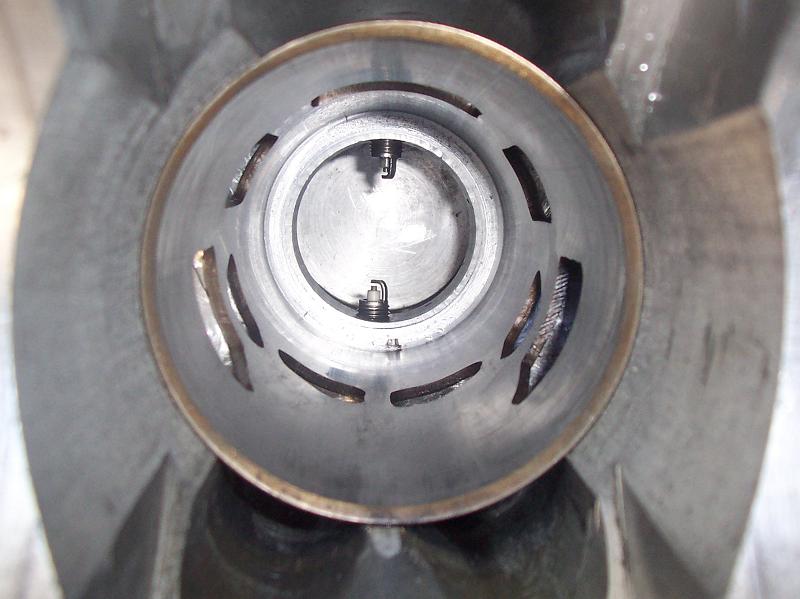
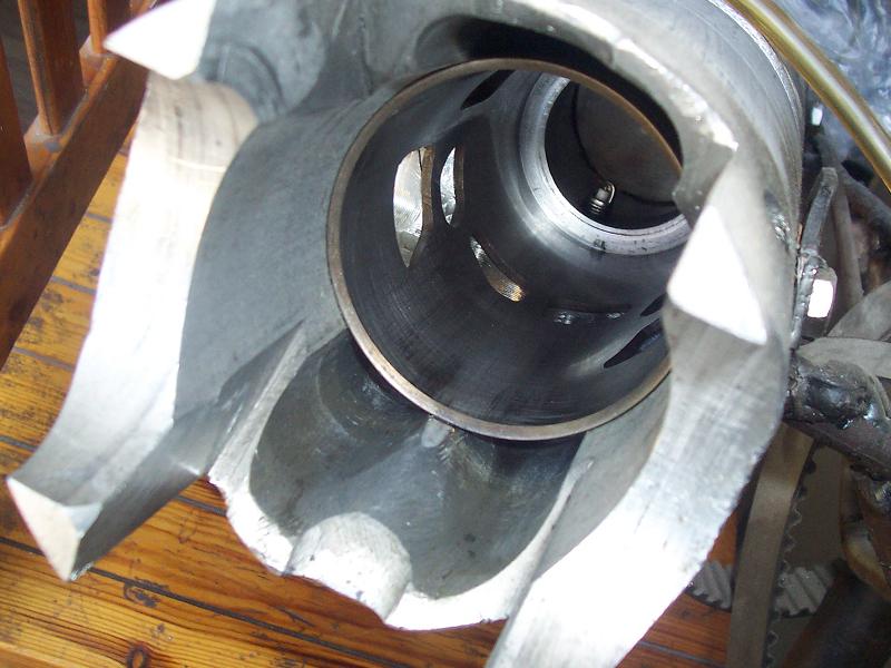
Here is a PatATeco turbo-charged indirectly-injected:
The same, stereoscopically from various view points:
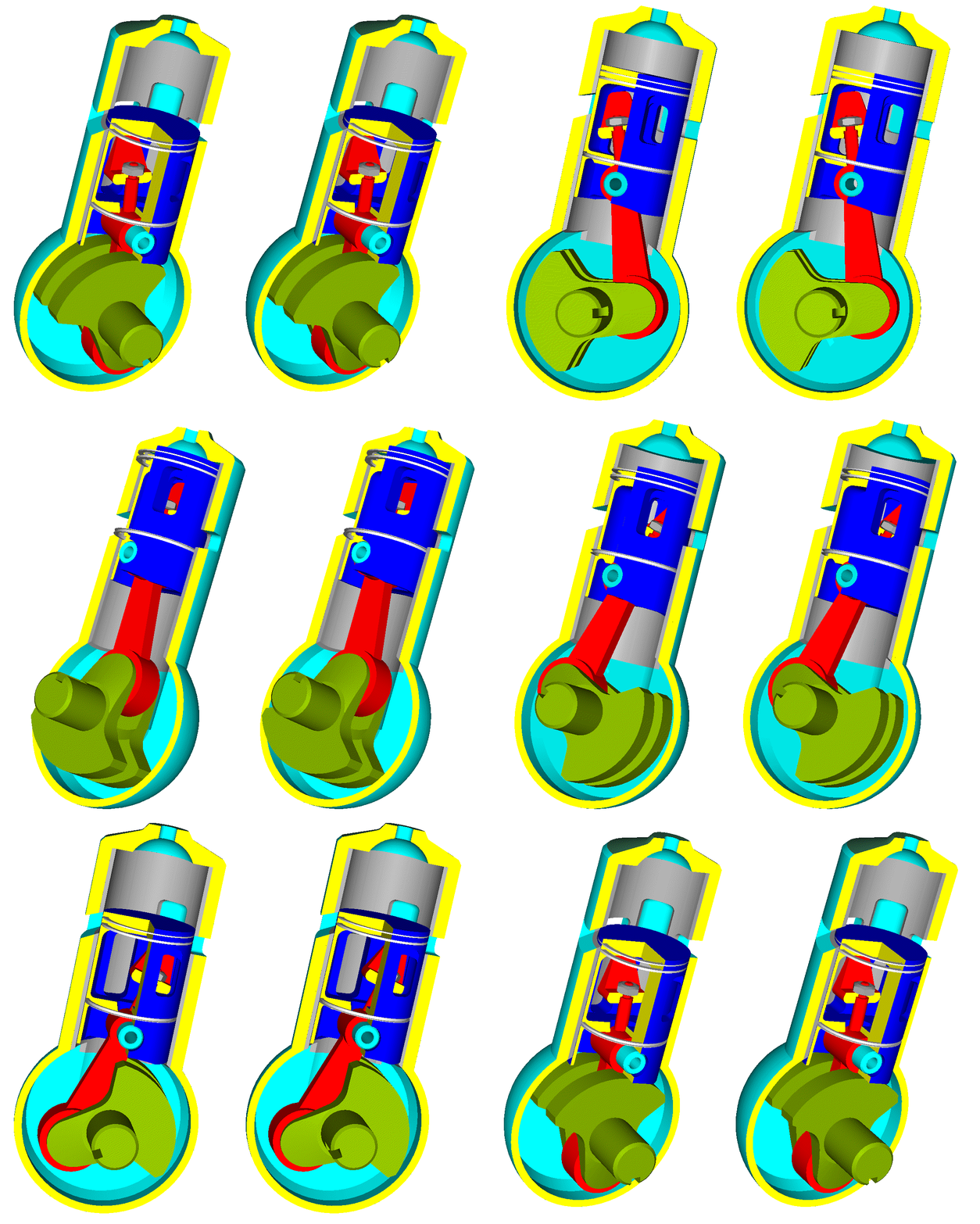
The above arrangement has '4T type' plain-bearing bottom-end: the crankcase is not pressurized, the bearings are plain bearings lubricated by lubricant under pressure, an oil scraper ring scraps the oil from the cylinder liner as in the 4-strokes, at the BDC the lower pressure ring of the piston abuts whereon the scraper ring was abutting 180 degrees earlier).
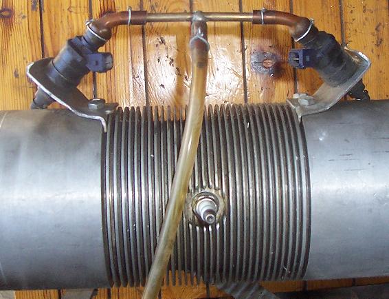
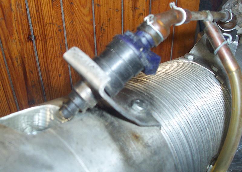
The engine is spark ignition and has indirect injection without compromising with the emissions:
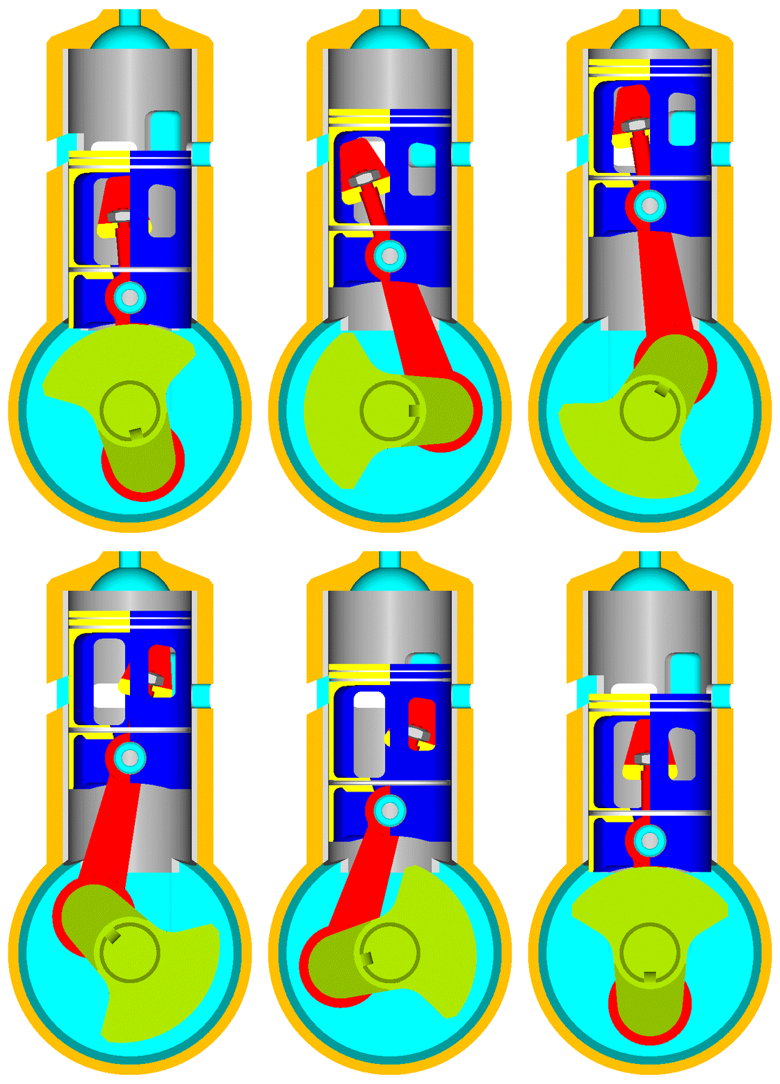
In the “flat” animation there are 24 slides (one slide per 15 crank degrees).
On the cylinder liner there is an exhaust port, at left, there are also three “filling” ports.
Follow the piston leaving the TDC.
Through the left “filling” ports and the long openings at the left side of the piston, the space underside the piston crown (which is isolated from the crankcase) fills with compressed air from the turbocharger (not shown).
Some 60 degrees after the TDC the connecting rod closes the holes / passageways of the asymmetric transfer at the right side of the piston.
Then, say though the left “filling” port or otherwise, a fuel injector injects fuel towards the upper right end of the space underside the piston crown, wherein it forms a rich mixture with the air.
Later the exhaust starts and the pressure in the cylinder drops.
Later the scavenging start: compressed air from the turbocharger, through the “filling” ports (which are now above the piston top), enters into the cylinder and sweeps the burned gas to the exhaust.
Later the “filling” ports close by the upwards moving piston, while the exhaust is still open.
Later the asymmetric transfer ports open by the upwards moving piston and the exhaust port closes. The compressed air in the space underside the piston crown pushes the rich mixture to pass into the cylinder through the asymmetric ports, over-filling the cylinder, while fresh compressed air enters in the space underside the piston crown through the left “filling ports (which are now “below” the piston crown). A little before the closing of the asymmetric transfer ports, a gust of compressed air from the space underside the piston crown enters into the cylinder cleaning the asymmetric transfer ports.
There are only three moving parts (as much as in the simplest conventional 2-strokes).
Bu the way, the animations are to show the principle of operation, are to show the difference from the prior art.
For instance, the asymmetric transfer can close substantially after, or a little after, or simultaneously, or a little before the exhaust.
Thanks
Manolis Pattakos

