2 stroke thread (with occasional F1 relevance!)

All that has to do with the power train, gearbox, clutch, fuels and lubricants, etc. Generally the mechanical side of Formula One.
J.A.W.
J.A.W.
109
Joined: 01 Sep 2014, 05:10
Location: Altair IV.

Re: 2 stroke thread (with occasional F1 relevance!)

Post

Hi Manolis,

Perhaps you may be underestimating the efficacy merits - of a scientifically validated exhaust design..

While the 'free' boost of sonic-pulse/shaped-charge designs used by 2T machines - has been well established for 60+ years..

Empirical research also shows the +ve volumetric efficiency effects of careful exhaust design for 4Ts too..
Indeed, tuner David Vizard describes this 4T exhaust design influence on VE potential - as a veritable "5th cycle".

http://www.superchevy.com/how-to/exhaust/0505phr-exh

Be assured, Ducati utilizes this factor on its race ( & race-homologation ) machines..

I'm confident that the readers of this thread are looking forward to seeing your innovative designs proved-in-metal, Manolis..
& you'd agree surely, that a selected for optimum design exhaust system - which forms an active role in engine efficiency..
..cannot possibly be relegated as an afterthought.. esp' in the 'here & now' of tight emissions regs...
"Well, we knocked the bastard off!"

Ed Hilary on being 1st to top Mt Everest,
(& 1st to do a surface traverse across Antarctica,
in good Kiwi style - riding a Massey Ferguson farm
tractor - with a few extemporised mod's to hack the task).

Pinger
Pinger
9
Joined: 13 Apr 2017, 17:28

Re: 2 stroke thread (with occasional F1 relevance!)

Post

manolis wrote:
03 Sep 2017, 12:33
and you have, for some 65-75 crank degrees, air, air-fuel mixture and fuel droplets entering violently into the cylinder, with the exhaust port open.

Well?

“What stops the fuel (already entered into the cylinder) from escaping to the exhaust?"
With only unfuelled air admitted early enough to reach the exhaust port while it is still open. The later charge carrying the fuel aimed at the spark plug will not have time to rise there and fall to the exhaust port before said port is closed.

The incoming charge is not one homogeneous bulk admitted to the cylinder in an infinitely small time frame, rather it is in the form of streams admitted over the time it takes the crank to rotate from transfer opening CA to just after BDC and is arranged to expel the residual exhaust gas. Blow down merely allows for the lowering of cylinder pressure. The cylinder is still full of exhaust gas at the time of transfer opening.

What would be more pertinent here Manolis is you expanding on your method of creating the essential pressure differential to create transfer flow to enable the above.
A very low delivery by crankcase alone will yield an engine fit for nothing better that a lawn mower (as has previously been mentioned) but at a build cost not acceptable and without an ability to exploit a return +ve pulse, an expansion chamber dragging charge into the exhaust pipe with no ability to return it to the cylinder is a non-starter.
Leaving only the (8bar BMEP) middle ground to inhabit but with no obvious cylinder charging mechanism compatible with your chosen transfer timings.

uniflow
uniflow
36
Joined: 26 Jul 2014, 10:41

Re: 2 stroke thread (with occasional F1 relevance!)

Post

Manolis, stick to fourstrokes. You need to read up on how high performance twostrokes work. A twostroke without a tuned exhaust is a lawn mower engine (or chainsaw) the worst fuel air bypass is off the pipe, this is where TPI works so well with the delayed injection. As KTM also eventually found this out with testing, not talking. In fact when the engine is up on the pipe there is not enough time to inject while the transfers are open, there is evidence that some fuel finds its way into the A ports as well as the B ports. BUT this is when there is enough inertia to keep the transfer streams headed where they have been directed by the port angles, lots of gas stream control. Also in fact some fuel air does end up out the exhaust port after the transfers are closed, this is mostly recovered by the pipe pressure and the reverse pulse pushing this fuel air back into the cylinder. Three of four pound pulse supercharge as well. You wont catch me running any of my development engines without this 'magic pipe', free HP.
Ultimately you need to control these transfer gas streams better. But I'm not about to tell you how to do that.
I guess proof of this reverse pulse pushing fuel air back into the cylinder is found in that if the cylinder exhaust port is heavily cooled detonation disappears and power increases substantially.

As I always say Manoils, build one and show us. That would be on a dyno not just free revving on the bench.

gruntguru
gruntguru
566
Joined: 21 Feb 2009, 07:43

Re: 2 stroke thread (with occasional F1 relevance!)

Post

I am sure there are plenty of two stroke experts out there that would love to get their hands on the means to make the timing of exhaust events independent from transfer events. Nothing about that capability precludes tuned pipe supercharging etc.
je suis charlie

AmiFlaneur
AmiFlaneur
0
Joined: 31 Oct 2016, 20:31

Re: 2 stroke thread (with occasional F1 relevance!)

Post

Kevin Cameron, the technical editor of Cycle World magazine wrote an article about KTM transfer port fuel injection a few weeks ago: Will KTM’s Clean Two-Stroke Make It To The Street?
http://www.cycleworld.com/ktm-transfer- ... for-street
Edit September 6th: My apologies for posting redundant information J.A.W. Thank you, I will take your advice.
Last edited by AmiFlaneur on 06 Sep 2017, 19:05, edited 1 time in total.

J.A.W.
J.A.W.
109
Joined: 01 Sep 2014, 05:10
Location: Altair IV.

Re: 2 stroke thread (with occasional F1 relevance!)

Post

AmiFlaneur wrote:
05 Sep 2017, 22:30
Kevin Cameron, the technical editor of Cycle World magazine wrote an article about KTM transfer port fuel injection a few weeks ago: Will KTM’s Clean Two-Stroke Make It To The Street?
http://www.cycleworld.com/ktm-transfer- ... for-street
Yeah A-F, he sure did, & in fact - that article has been linked here already; see: 1st post of the previous page..

If you have interest/knowledge/experience - in the thread subject, do feel free - to offer a considered view on the matter..
"Well, we knocked the bastard off!"

Ed Hilary on being 1st to top Mt Everest,
(& 1st to do a surface traverse across Antarctica,
in good Kiwi style - riding a Massey Ferguson farm
tractor - with a few extemporised mod's to hack the task).

manolis
manolis
107
Joined: 18 Mar 2014, 10:00

Re: 2 stroke thread (with occasional F1 relevance!)

Post

Hello J.A.W.

You write:
“Indeed, tuner David Vizard describes this 4T exhaust design influence on VE potential - as a veritable "5th cycle".”


With the exhaust “adding” a “5th cycle” in the 4-stroke engines,
the exhaust of a conventional 2-stroke can(?) be considered as adding “a 3rd and a 4th cycles” in the two cycles of the 2-stroke engine.


The exhaust of a 2-stroke PatATE seems as important as the exhaust of the 4-strokes.
I.e. in the PatATE the intake has the dominant role, as happens in the 4-strokes.

Thanks
Manolis Pattakos

manolis
manolis
107
Joined: 18 Mar 2014, 10:00

Re: 2 stroke thread (with occasional F1 relevance!)

Post

Hello Pinger.

You write:
“The incoming charge is not one homogeneous bulk admitted to the cylinder in an infinitely small time frame, rather it is in the form of streams admitted over the time it takes the crank to rotate from transfer opening CA to just after BDC and is arranged to expel the residual exhaust gas. Blow down merely allows for the lowering of cylinder pressure. The cylinder is still full of exhaust gas at the time of transfer opening.”


It doesn’t fit.

Fuel and air are drawn in a cylinder having a widely open exhaust port.

At all conditions (revs, loads) the fuel remains into the cylinder (because it was injected the “right(?) time”) and only a part of the air exits towards the exhaust and re-enters into the cylinder.

Sorry, but let me doubt, strongly.

Thanks
Manolis Pattakos

manolis
manolis
107
Joined: 18 Mar 2014, 10:00

Re: 2 stroke thread (with occasional F1 relevance!)

Post

Hello Gruntguru.

You write:
“I am sure there are plenty of two stroke experts out there that would love to get their hands on the means to make the timing of exhaust events independent from transfer events. Nothing about that capability precludes tuned pipe supercharging etc.”


Thank you for replying for me.


Lately we have been involved / meshed with another project, the PatEf:

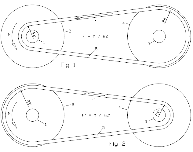
In Fig. 1 a V-belt CVT is shown at a short transmission ratio (drive shaft: 1, drive pulley: 2, driven shaft: 3, driven pulley: 4, V-belt: 5).
Image

The torque M provided by the drive shaft 1 loads the V-belt by a force F=M/R2, wherein R2 is the radius at which the V-belt runs on the drive pulley 2.

In order to avoid "belt slippage" in the drive pulley, a minimum clamping of the V-belt between the two conical halves of the drive pulley 2 is required.

The same for the rear pulley: a minimum clamping is required, otherwise the pulley cannot apply the required force on the V-belt.

In Fig. 2 the transmission ratio (defined as the ratio of the angular velocity of the driven pulley 4 to the angular velocity of the drive pulley 2) is long, about double than in Fig. 1.

With the same torque M provided by the drive shaft 1, the substantially bigger radius R2' the V-belt runs on the drive pulley 2 reduces substantially the force F' loading the V-belt (F'/F=R2/R2') and proportionally the required clamping of the belt between the two conical halves of the drive pulley 2, and similarly it reduces proportionally the required clamping of the V-belt between the two conical halves of the driven pulley 4.

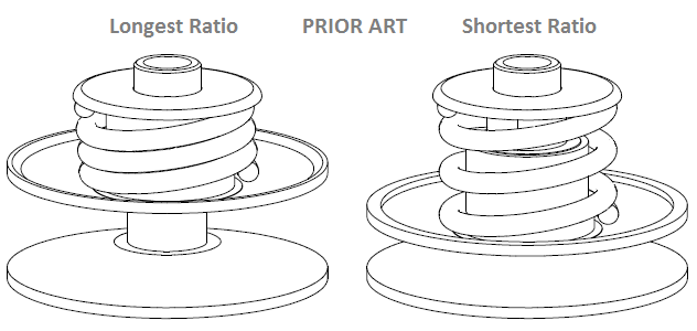
However, as shown in the following drawing, the driven pulley spring of a conventional CVT is heavily over-compressed at the longer transmission ratios.
Image

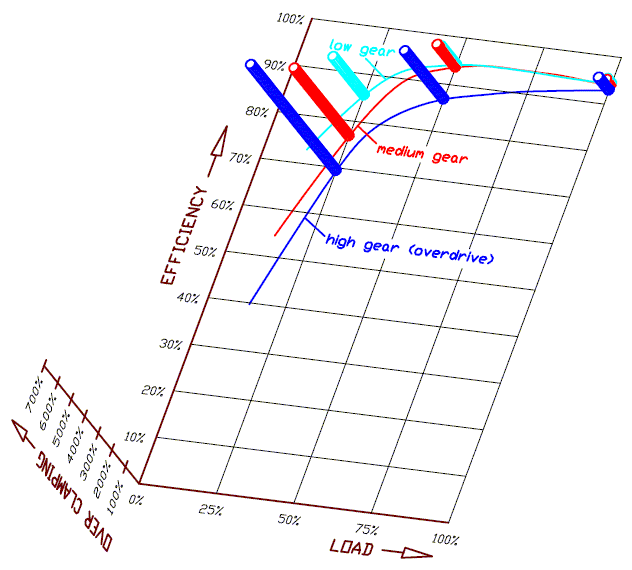
While the efficiency (i.e. the ratio of the output power to the input power) of a conventional V-belt CVT peaks, at the shorter transmission ratios and the heavier loads, even above 95%, the efficiency drops well below 85% at the longer transmission ratios (overdrive) and the lighter loads.
Image

The low efficiency of the conventional V-belt CVT at the long transmission ratios comes from its architecture according which: a variator (or governor) at the drive pulley pushes its two halves close to each other, while a spring in the driven pulley is resisting and is forcing the two halves of the drive pulley away from each other.


And here is the principle according which the PatEf operates:
Image

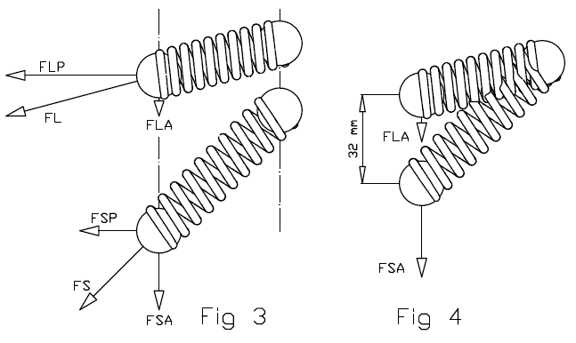
In Fig. 3 as the spring is more compressed, the force (FS, FL) it applies along its direction increases: FL>FS (the L stands for longer ratios, the S stands for shorter ratios).

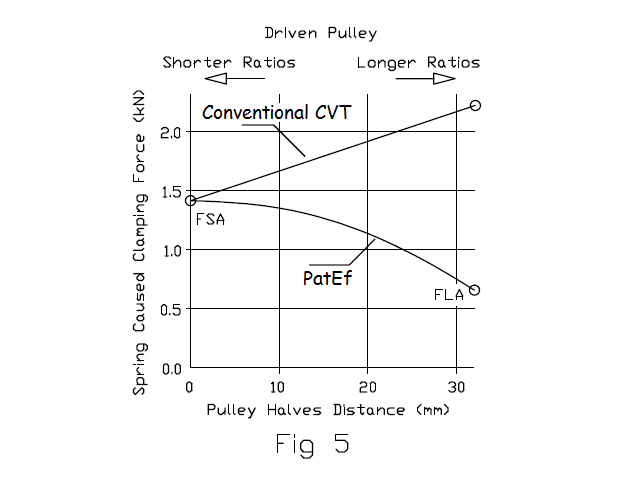
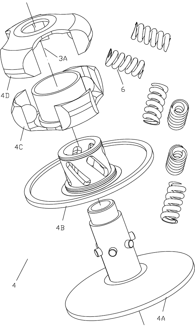
Analyzing the total force FL in an axial component force FLA parallel to the rotation axis 3A of the driven shaft 3 (the A in the FLA stands for axial) and in a perpendicular component force FLP on a plane perpendicular to the rotations axis 3A (the P in the FLP stands for perpendicular), and similarly for the FS which is analyzed in an axial component force FSA (parallel to the rotation axis 3A) and in a perpendicular component force FSP (on a plane perpendicular (normal) to the rotation axis 3A), despite the increase of the total force the spring applies at the longer ratios (because it is further compressed), the axial component of the force can reduce substantially at the longer transmission ratios (and proportionally can reduce the clamping of the V-belt), as the following plot shows:
Image

The arrangement of the springs is such that, while for higher and higher transmission ratios the springs are more and more compressed (providing a stronger and stronger force), the axial forces the springs apply on the two halves of the driven pulley (and the clamping of the V-belt these forces cause) is reduced.

The above plot shows the "spring caused clamping" versus the distance between the two halves of the driven pulley for a conventional CVT and for a CVT having the PatEf (to be noted: at 0mm distance, the two halves are at the closest to each other position, which means the V-belt is running at the maximum diameter in the driven pulley).
Image

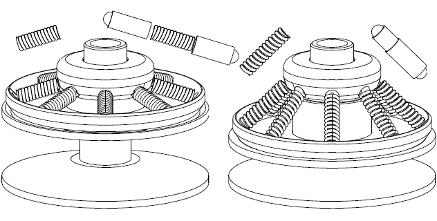
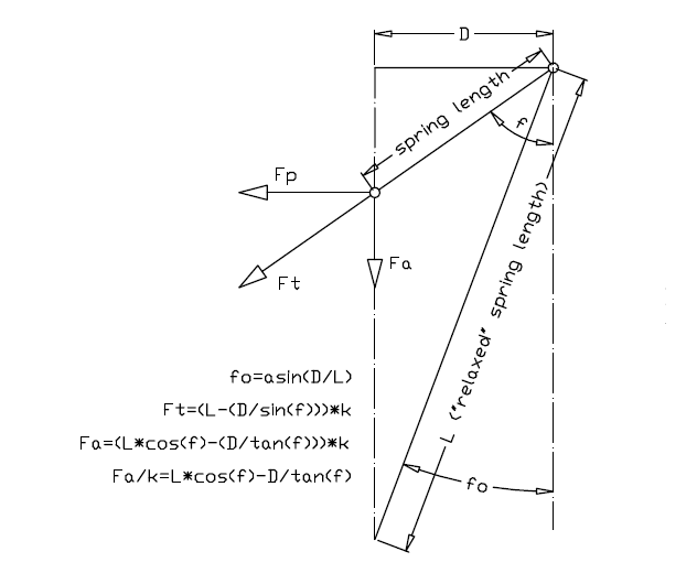
The above drawing shows the arrangement of a spring (actually of the axis of a spring) of the PatEf.

The relaxed length of the spring (i.e. the length of the spring when it is unloaded) is L, and its projection on a horizontal axis has constant length D due to its arrangement.

The axis of the spring has an inclination f relative to the rotation axis of the driven pulley (the rotation axis of the driven pulley is not shown, but it is parallel to the dashed-dot lines of Fig 31).

The total force provided by the spring is Ft along the spring "axis", with:

Ft=(L-(D/sin(f)))*k, wherein k is the stiffness of the spring.

The axial component of the Ft is Fa, with:

Fa=(L*cos(f)-(D/tan(f)))*k

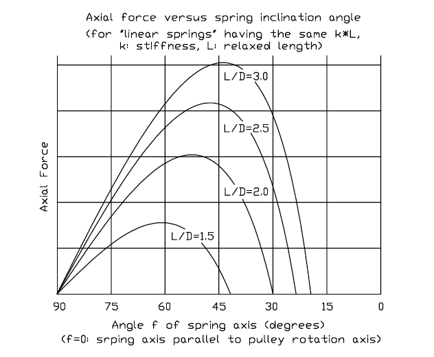
In the following plot it is shown the resulting axial force versus the spring inclination angle of the arrangement in the above drawing, for springs having various lengths.
Image

For the specific plot (but not obligatory) the stiffness k of each spring is taken reverse proportional to its length, which means constant k*L (to make springs of constant k*L one could use the same wire, the same coil diameter and the same pitch).

Following the curve "L/D=2.5", one can see that the resulting axial force is zero until f=23.5 degrees (relaxed spring, asin(1/2.5)=23.5 degrees). Then the spring is progressively compressed.

Until f=48 degrees the axial force increases with the compression of the spring (but not linearly).

After the 48 degrees (at which the curve "L/D=2.5" maximizes), while the further increase of the angle f of the spring axis causes the further compression of the spring (because its effective length reduces), the resulting axial force reduces.

From 60 to 90 degrees (at 90 degrees the resulting axial force gets zero) the drop of the axial force varies, more or less, linearly with the angle f.

For instance, designing the driven pulley and its springs so that at the shortest transmission ratio (i.e. completely closed driven pulley and V-belt runsing at the maximum diameter on the driven pulley) the spring inclination to be f=53 degrees, and at the longest transmission ratio (i.e. completely open driven pulley and V-belt running at the minimum diameter on the driven pulley) the spring inclination to be f=75 degrees ("Axail force vs Spring inclination angle" plot), the resulting axial force (and the clamping it causes on the V-belt) reduces progressively and substantially as the transmission ratio increases.
The resulting axial force (and the clamping it causes) at the longest transmission ratio is nearly 50% of what it is at the shortest transmission ratio.
The 50% reduction of the clamping force at the longest transmission ratio fits well with what the Figs. 1 and 2 show.


Practically:
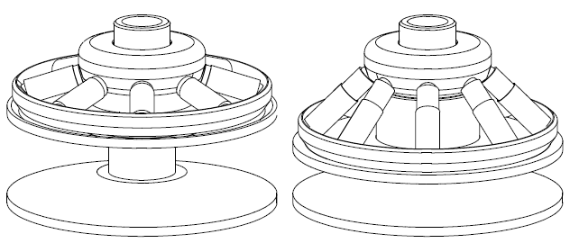
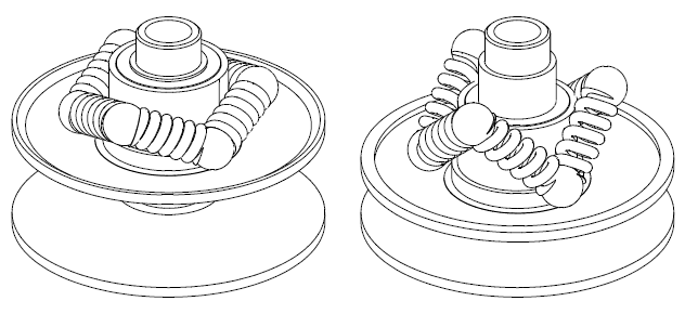
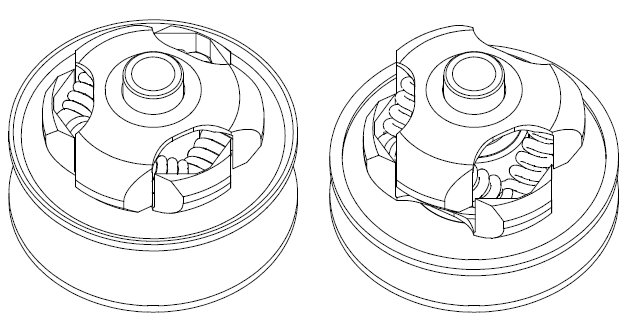
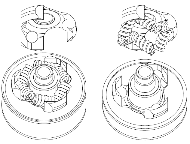
Image

Image

If the driven pulley of a scooter CVT is modified to PatEf, the ramps and the roller weights of the variator have also to be modified to fit with the substantially different clamping of the V-belt along the operating range.

After the modification, the scooter (or vehicle in general):

will be greener / more fuel efficient (a part of the fuel previously burnt to provide energy consumed in the CVT as friction, is saved),

the scooter will have higher top speed,

the CVT will run substantially colder and will need less energy for cooling / ventilation,

the V-belt will last far longer (because it avoids running under extreme over-clamping).
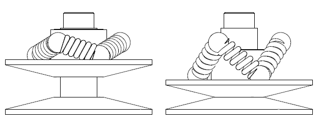
Image

Image

Image

Image

Image

The mechanism fits also with bicycles having a V-belt CVT for the transmission from the pedals to the rear wheel (as in the GB 2,526,675 patent (PatBox CVT), for instance).

The reduction of the over-clamping (and of the associated friction loss) is more significant in a bicycle because of the small available human power.

The simplicity is among the characteristics of the PatEf.

The saving of fuel and of power are also characteristics of the PatEf.

The "automatic operation" is also a characteristic of the PatEf: after the assembly of the driven pulley, the reduction of the clamping force is realized automatically without external parts or control systems.
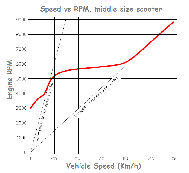
Image

According the previous:

With the PatEf the mileage of a conventional middle size scooter can be improved more than 10% at typical highway cruising (say, 100Km/h (62mph) wherein the engine runs at medium load and wherein, according the above plot, the CVT runs already at (or near) its longest transmission ratio, which means the V-belt, in case without the PatEf, runs under extreme over-clamping (see the "efficiency vs over-clamping" plot, third image from top in this web page).
With some three times lighter V-belt clamping, the expected durability of the V-belt gets several times longer.

With the PatEf the scooter can also accelerate faster because a part of the energy previously consumed on the V-belt and on the pulleys, now accelerates the scooter, reducing at the same time the V-belt wear.

With the PatEf the scooter can also achieve a higher top speed. Because at the maximum speed the CVT cannot help running at its longest transmission ratio wherein the over-clamping of the V-belt consumes (in friction and belt wear) a part of the power provided by the engine; with the PatEf, this power part is utilized: it is pushing the scooter / sled / ATV / car / bicycle forwards, improving at the same time the durability of the V-belt .


Thoughts ?

Thanks
Manolis Pattakos

J.A.W.
J.A.W.
109
Joined: 01 Sep 2014, 05:10
Location: Altair IV.

Re: 2 stroke thread (with occasional F1 relevance!)

Post

manolis wrote:
06 Sep 2017, 07:05
Hello J.A.W.

You write:
“Indeed, tuner David Vizard describes this 4T exhaust design influence on VE potential - as a veritable "5th cycle".”


With the exhaust “adding” a “5th cycle” in the 4-stroke engines,
the exhaust of a conventional 2-stroke can(?) be considered as adding “a 3rd and a 4th cycles” in the two cycles of the 2-stroke engine.


The exhaust of a 2-stroke PatATE seems as important as the exhaust of the 4-strokes.
I.e. in the PatATE the intake has the dominant role, as happens in the 4-strokes.

Thanks
Manolis Pattakos
Hi Manolis..

Actually, in the view of David Vizard, the role of the exhaust in a high output 4T application - is of major importance..
He writes:

"Compared with intake, exhaust tuning is far more potent, & can operate over 10 times as wide an rpm band."

& as we know, in 2T operation, all the working fluid pumping functions are cycled - in 1/2 the 4T's reciprocation routine..
..thus getting the synergistic gas-flow path to pulse in harmonisation - is a must, for really effective 2T power/efficiency..


This is what Uniflow & Pinger have been duly placing emphasis on, in their recent posts..
"Well, we knocked the bastard off!"

Ed Hilary on being 1st to top Mt Everest,
(& 1st to do a surface traverse across Antarctica,
in good Kiwi style - riding a Massey Ferguson farm
tractor - with a few extemporised mod's to hack the task).

manolis
manolis
107
Joined: 18 Mar 2014, 10:00

Re: 2 stroke thread (with occasional F1 relevance!)

Post

Hello J.A.W.

You write:
"
Actually, in the view of David Vizard, the role of the exhaust in a high output 4T application - is of major importance..
He writes:
"Compared with intake, exhaust tuning is far more potent, & can operate over 10 times as wide an rpm band."
"

The role of the exhaust "in a high output 4T application" is of major importance.

Image

but not in normal green 4-stroke engines, wherein the extended overlap is a problem, not a solution.


I think here is wherein the point is missed:

Nobody can argue that the 2-strokes can make lots of power.
However they are problematic as regards their emissions.
The focus must be on the emissions.
On anything that can lower the emissions, even at the expense of power.


The PatATE suggests a substantially different way of operation of the 2-strokes.
And combines several unique characteristics not met in other 2-strokes (like the cold exhaust (which means, among others, substantially lower specific lube consumption), like the extreme rate of exhaust area opening, like the substantially earlier closing of the exhaust etc)


Since the lawn mower engine

Image

is the favourite reference here, let's see how it handles the charge.

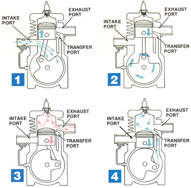
The exhaust port opens early, otherwise the crankcase, when the piston opens the transfer port, will fill with burnt gas.
After the end of the transfer, the still wide open exhaust port provides a "free way" to the fresh mixture to escape. Say as the Atkinson - Miller cycle does in the 4-strokes, but here anything that leaves the cylinder is lost and pollutes.
At the end of the exhaust, a good part of the entered air or air-fuel-mixture is not in the cylinder, and the torque drops dramatically.


And here is how things work in the PatATE:

The exhaust can open later; the rate the exhaust opens is substantially higher than in a conventional allowing the faster blow-down even with substantially later exhaust opening.
From the beginning the PatATE has a gain (on thermal efficiency and on torque) due to the extended expansion allowed by the later exhaust opening.

At the end of the blow-down the transfer opens and the scavenging starts.
The air / air-fuel mixture from the crankcase gathers progressively speed and inertia (as happens during the overlap of the sport/racing 4-strokes, article of David Vizard), with the pressure in the crankcase dropping progressively.
The entering air-mixture expels the burnt gas out of the cylinder.

Then the exhaust closes. The exhaust can close more than 50 crank degrees earlier than in the conventional lawn mower 2-stroke engine.

During the closing of the exhaust, the rotary valve of the PatATE opens the intake port (without a reed valve to delay the begining of the intake stream).

The vacuum created in the crankcase due to the inertia of the air / mixture going from the crankcase to the cylinder, suctions new air /mixture into the crankcase through the open intake port. Like a supercharger, but for free.

When the transfer port finally closes, the quantity of air /mixture trapped into the cylinder for compression / combustion / expansion has nothing to do with a lawn mower.

According the previous analysis, the quantity of air /mixture that can be trapped into the cylinder of the 2-stroke PatATE (or, differently, the volumetric efficiency) is comparable with the quantity of air /mixture trapped in the cylinder of the sport-racing 4-strokes, like the Ducati Panigale.
And if you double the specific torque of the Panigale (because the PatATE is a 2-stroke), the expected specific torque becomes more than 30% higher than in the green KTM EXC250TPI / 2018.


Where is the mistake or the trick?

Does the PatATE design fit with lawn mower engines or with green super-2-strokes?

Thanks
Manolis Pattakos
Pinger
Pinger
9
Joined: 13 Apr 2017, 17:28

Re: 2 stroke thread (with occasional F1 relevance!)

Post

manolis wrote:
07 Sep 2017, 07:47


The vacuum created in the crankcase due to the inertia of the air / mixture going from the crankcase to the cylinder, suctions new air /mixture into the crankcase through the open intake port. Like a supercharger, but for free.

Just look at the pumping efficiencies of the two competing chambers, one with a pressure ratio of 7.5:1 (minimum), the other with circa 1.4:1 and you believe that inertia will overcome the cylinder's ability to reverse the transfer flow and direct it back to the crankcase? Not a chance.
manolis wrote:
07 Sep 2017, 07:47
According the previous analysis, the quantity of air /mixture that can be trapped into the cylinder of the 2-stroke PatATE (or, differently, the volumetric efficiency) is comparable with the quantity of air /mixture trapped in the cylinder of the sport-racing 4-strokes, like the Ducati Panigale.
I think you need to understand the difference between 'perfect displacement' (unachievable) scavenging and 'diffusion' in scavenging. When you do, you will realise that 4T levels of volumetric efficiency are impossible in a 2T (without copious (costly) over supply of purging air) and not required as the firing on every stroke coupled to other merits (eg, low friction, bulk, mass, etc) are compensation enough.

If you want 4T volumetric efficiency - build a 4T.

J.A.W.
J.A.W.
109
Joined: 01 Sep 2014, 05:10
Location: Altair IV.

Re: 2 stroke thread (with occasional F1 relevance!)

Post

Hi Manolis..

Yes, you are correct to note volumetric efficiency in sports/race performance engine 'powerband' parameter terms..
..so the Ducati Panigale uses its vast engine capacity/light weight - to overcome low rpm torque deficiencies..

But variable valve timing/flow control.. has been available for decades.. in both 2T & 4T road-vehicle usage..
& Uniflow has demonstrated (in-metal/empirically in operation) the efficacy of 2T TFI & variable rotary inlet valve tech..
"Well, we knocked the bastard off!"

Ed Hilary on being 1st to top Mt Everest,
(& 1st to do a surface traverse across Antarctica,
in good Kiwi style - riding a Massey Ferguson farm
tractor - with a few extemporised mod's to hack the task).

manolis
manolis
107
Joined: 18 Mar 2014, 10:00

Re: 2 stroke thread (with occasional F1 relevance!)

Post

Hello all.

I read:

I think you need to understand . . .. When you do . . .

also:

"build one and show us"


To show that an engine is euro4 or euro5 compliant is far more difficult and costly than measuring the fuel consumption.

And it took almost 20 years from the filing of the 2-stroke TPI patent of Rotax (previous post) till a 2-stroke TPI to be officially tested on the roads by KTM (reasonably, KTM has to pay royalties to Rotax).


Let’s try, without making it in metal, to understand how things work in the 4-stroke Ducati Panigale, and then apply the results in the PatATE.

Here are the torque curves of the Panigale 1299 and 1199 (the dashed line is for the 1199):

Image

At 9,000rpm the 1199 makes 110mN/lit specific torque and keeps it till 10,500rpm of the peak power.

At only 4,000tpm it makes “just” 90mN/lit specific torque, which is good for most 4-strokes.

The “hole” from 4,500 to 7,000rpm seems deep only because the peak torque is so high.


Worth to note:

There is neither VVA (Variable Valve Actuation) nor VVT (phaser) in this top technology engine.
Just four big valves per cylinder actuated desmodromically.


Quote from http://www.cycleworld.com/2014/09/12/te ... ght#page-9

Image

“9) ...while the 1199 Superleggera uses titanium for intake and exhaust also by Del West. Each titanium exhaust valve saves 24 grams over its steel counterpart on the 1199 Panigale. Reduced inertia means the engine is capable of more revs. Valve lift is unchanged: 16mm intake, 14.3mm exhaust. There is a slight difference in the intake cam timing, although duration remains the same. The Superleggera intake cam is rotated 4 degrees backward, opening 15 degrees BTDC and closing 64 degrees ABDC (19 and 60 degrees, respectively, on the Paginale unit).


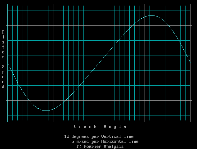
In the following plot (Piston Speed versus Crank Angle):

Image

the piston speed at 15 degrees after the TDC is less than 1/3 of the maximum piston speed at middle stroke.

No matter what, the inertia of the exhaust helps substantially the filling of the cylinder.

During the overlap, the inertia of the gas in the exhaust creates a vacuum that suctions, through the opening intake valves, air /mixture accelerating it.
When the exhaust valves finally close (15deg ATDC), the air / mixture coming from the intake finds the exhaust closed and a still slow moving piston.
The inertia of the “intake column” increases the pressure just before the intake valves and inside the cylinder (the kinetic energy of the “intake column” turns to “dynamic energy”).
And as the piston accelerates towards the BDC the pressure drops and the speed of the air / mixture from the intake valves increases.


Despitethe fact that the exhaust and the intake were “met” for only 30 degrees (and with a substantially low average valve lift during the 30 degrees of the overlap), the job was done by turning the velocity to pressure and back to velocity.

The Panigale Superleggera makes 200hp from two cylinders and 1200cc.


Now, please read again my last post and write where the mistake / trick is.

After the paragraph:

“When the transfer port finally closes, the quantity of air /mixture trapped into the cylinder for compression / combustion / expansion has nothing to do with a lawn mower.”

It can be added:

“Just before the closing of the transfer port, and due to the inertia of the entering air / mixture, the pressure in the cylinder is higher than in the crankcase which, at the same time, is fed, with air /mixture entering through the intake port.
After the closing of the transfer, the flow through the intake port to the crankcase continuous (due to the inertia, again) becoming stronger and stronger as the piston moves towards the TDC (due to the crankcase sub-pressure, this time).
The filling of the crankcase continues for several (say 60?) degrees after the TDC, even after the crankcase pressure is above the ambient pressure, due to the inertia again.
Then the intake port closes by the rotary valve of the PatATE and the compression in the crankcase starts.”

Thanks
Manolis Pattakos

Tommy Cookers
Tommy Cookers
643
Joined: 17 Feb 2012, 16:55

Re: 2 stroke thread (with occasional F1 relevance!)

Post

don't mistake me for a person who has said anything against Manolis's 2 stroke

regarding the Panigale and Superleggera plots ......

is the given valve timing correct ? (ie is it run timing not eg values at a special large valve clearance for timing definition only ?)
because the declared overlap of 30 deg or 38 deg seems far too small for such a very high performance engine spec

nearly 60 years ago BSA made a similar niche version (single cylinder) road machine - it had 115 deg of valve overlap
unsurprisingly it could not reach maximum speed unless taken to peak power rpm through the gears
the Ducati torque plots show the same fault (that would occur in a single cylinder version)
they are bizarrely unsuited to road-normal use (like the RD350 as exposed here, or worse)
afaik they would not be allowed in F1 torque mapping

hasn't the position been that claims in Vizard's article apply only with a race or similar high-overlap cam ?