Hello Peppo.
You write:
“Please let me have your comments.”
A few thoughts / questions / comments on your design:
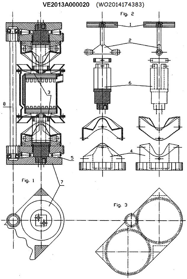
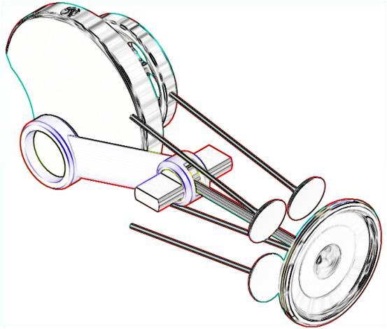
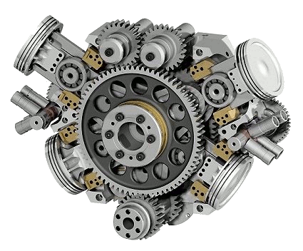
In the above drawing, at left, they are shown two pairs of conical rollers per piston. The one pair is rotatably mounted on the piston, the other pair is disposed between the immovable casing and the rotating big gearwheels (those with the circular-wave- tracks) to receive the axial loads.
Is the hatching correct? (as it is now, the rotating gearwheel is like being a part of the casing; shouldn’t its hatching be at a different angle or density, to distinguish it from the casing?).
The two conical track-roller-bearings on each piston are cooperating with a pair of facing each other circular-wave-tracks.
What happens when the force between the piston and the circular-wave-tracks changes direction?
Doesn’t each conical track-roller-bearing have to change –instantly- direction of rotation?
Reasonably, each piston should have two pairs of conical-track-roller-bearings (preloaded between the two trackways), the strong one running on the outer circular-wave-track, the other running on the inner. To keep the height low, the second pair of conical-track-roller-bearings can be disposed at, say, 90 degrees from the other pair.
The piston assembly seems lightweight in the drawing.
But the loads are heavy and the revs the conical-track-bearings operate are high. Are there such high-revving and strong track-rollers in the market?
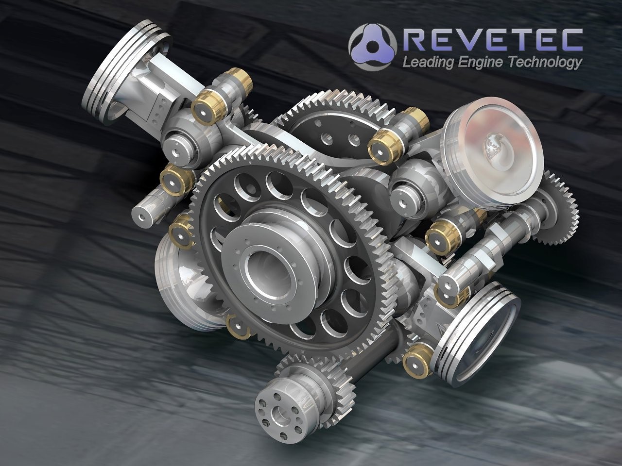
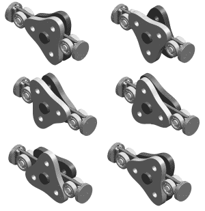
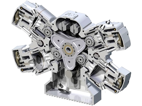
Judging from the size of the cylindrical-track-roller-bearings of the Revetec engine (which, as the Bourke engine, failed to operate reliably for longer than a few minutes because of the extreme local loading at the line-contact between the track-roller-bearings and the track-ways):

it seems that substantially oversized conical-track-roller-bearings are required in your design, which leads to substantially bigger in diameter circular-wave-tracks.
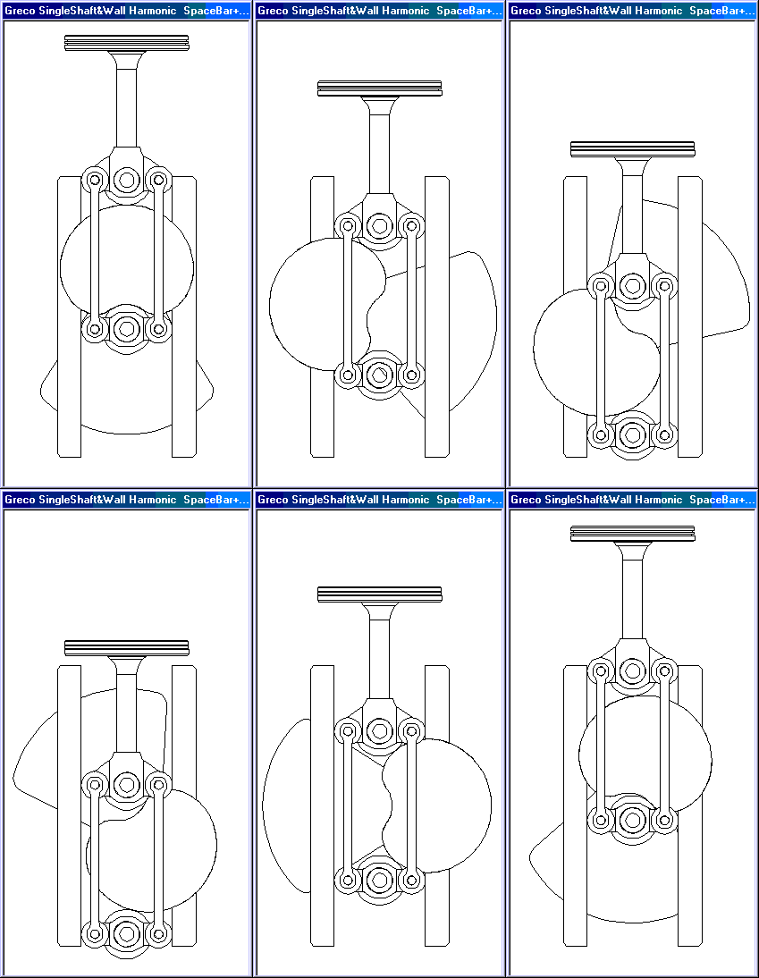
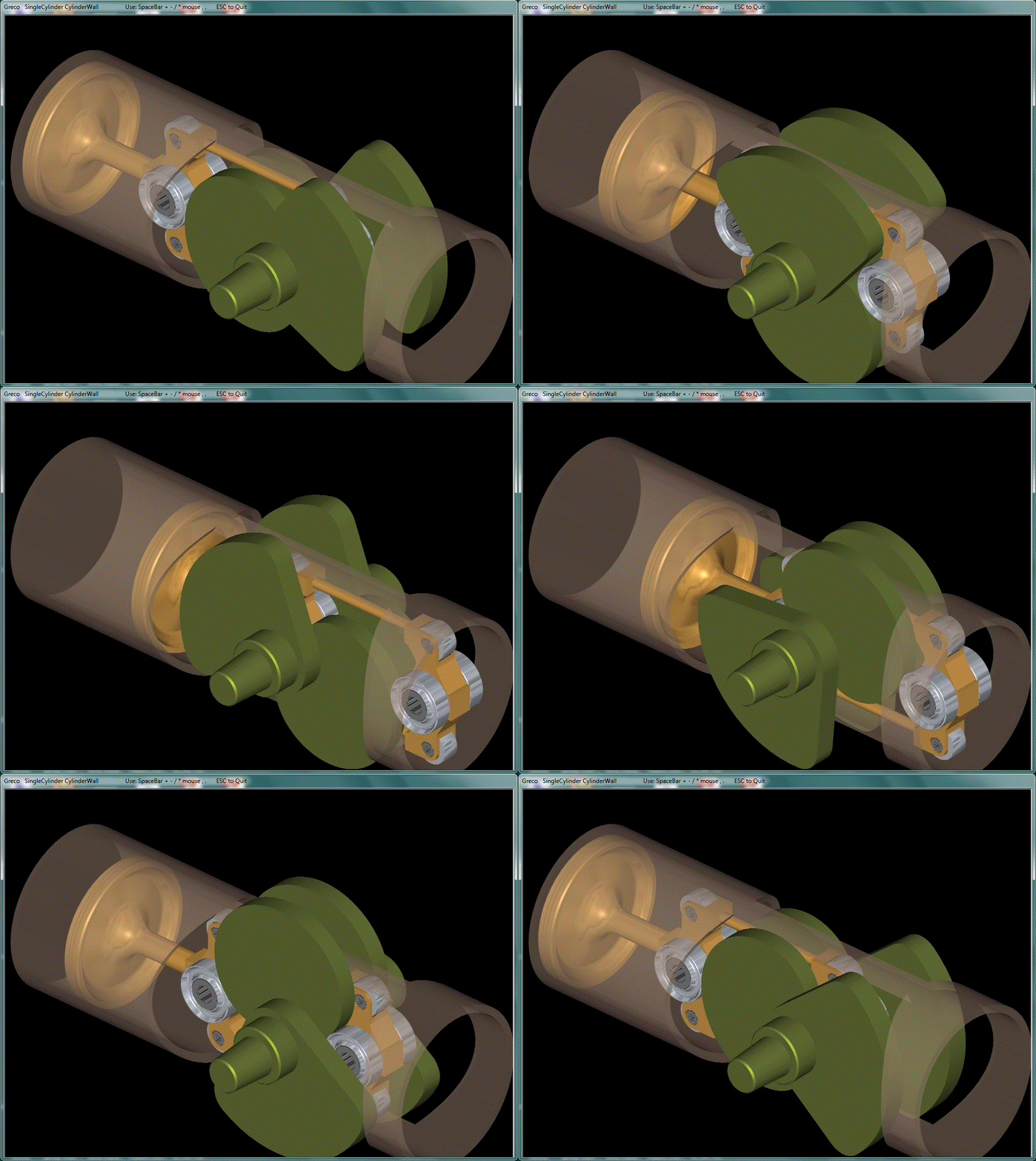
In the Cox Scotch Yoke design (previous posts) they use “surface” contact, which has the highest loading capacity in expense of frictional loss.
In the Revetec design, there is, permanently, a linear contact between the track-roller-bearing and the track-way, while each track-roller-bearing rotates permanently at the same direction (yet, at variable speed, which is still a big problem), allowing rolling without sliding (at least at the lower revs; at the medium - high revs the cylindrical-track-roller-bearings of the Revetec and of the Bourke cannot help sliding (besides rolling) on the track-way; to cure this problem mce-5 used the following solution:
Quote from
http://www.mce-5.com:

The synchronized roller is largely responsible for the low-friction performance of the MCE 5 VCRi

The MCE 5 VCRi synchronized roller cooperates with 3 synchronization racks: two of them are on a plate fixed to the crankcase while one is on the back side of the piston rack
End of Quote
despite their synchronized track rollers, and despite the 100 million euros, or so, funded to mce-5 VCRi, they now appear as closed / bankrupted: in their web site the “latest news” are from 2013).
In your design, is it possible to keep permanently at least “linear contact”? (and not turn it, at some parts of the track-ways, to “point-contact”?). To take the combustion loads with “point contact” is highly questionable (from the reliability viewpoint).
To put it differently: how the conical-circular-track-ways are designed?
If the track-way is conical (zero stroke of the piston), then the conical-track-roller-bearing rolls on the track-way without sliding and keeps - permanently - linear contact.
But if you add a significant axial displacement (piston stroke happening into 90 degrees of totation of the track-way) the complete track roller bearing displaces linearly along the cylinder axis, causing the sliding between the cooperating "conical" and "wave conical" surfaces.
Secondary “issues”:
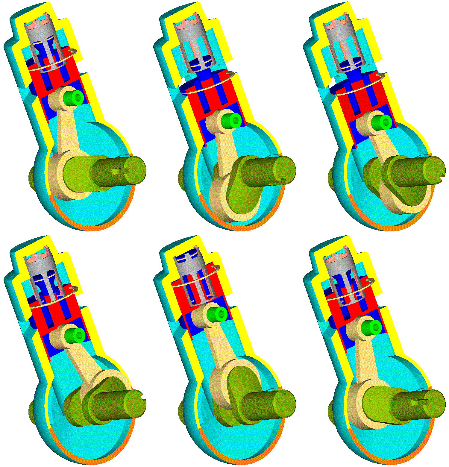
Doesn’t the piston at the exhaust side need a skirt to cover the exhaust ports when the piston is near the TDC? Even if the bottom of the cylinder is closed / sealed, the exhaust hot gas will return at the space underside the exhaust-piston.
Where the power is provided from? The synchronizing shaft, at left, is not extending out of the casing.
Don’t get me wrong.
I am just trying to help.
As an independent third party, I point on possible issues you may find in practice.
If anything I wrote is confusing please let me know to further explain.
Thanks
Manolis Pattakos
