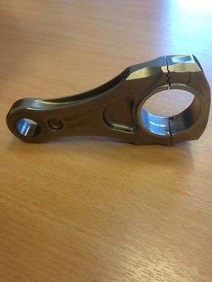
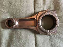
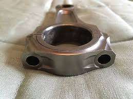
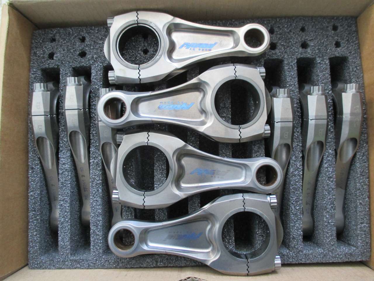
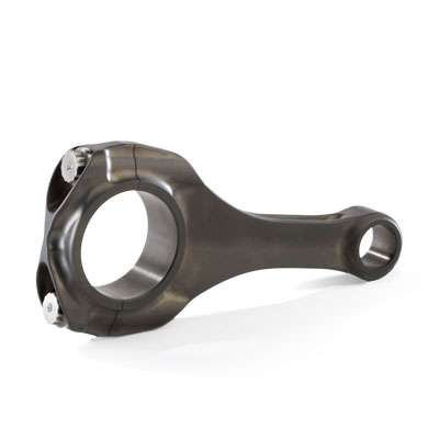
F1 Conrods

All that has to do with the power train, gearbox, clutch, fuels and lubricants, etc. Generally the mechanical side of Formula One.
e36jon
e36jon
66
Joined: 25 Apr 2016, 02:22
Location: California, USA

F1 Conrods

Post

Greetings all

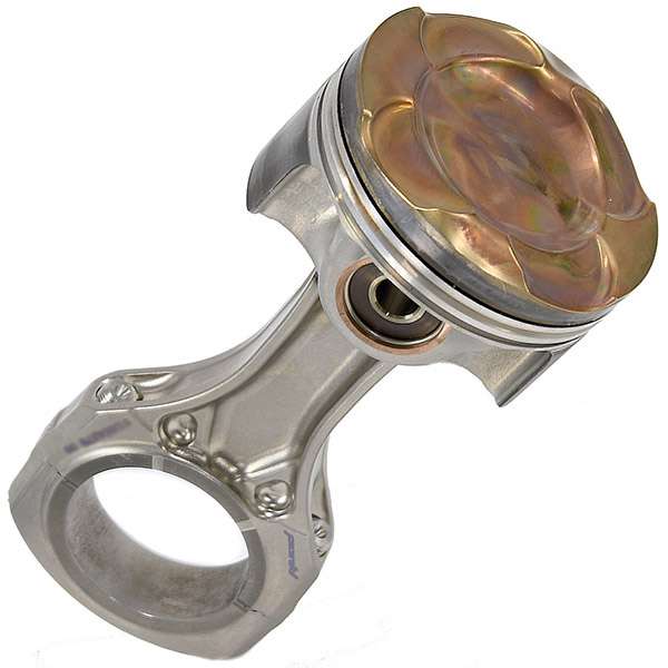
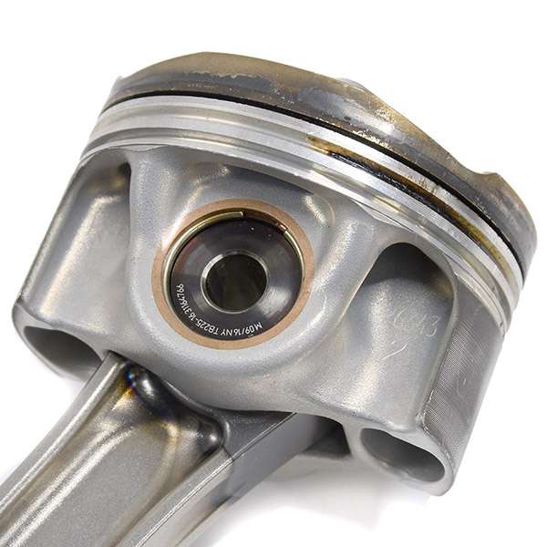
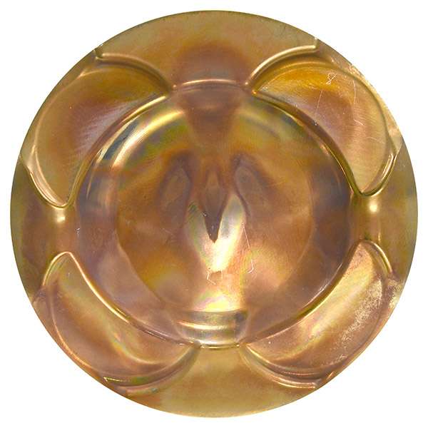
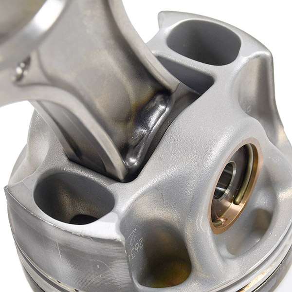
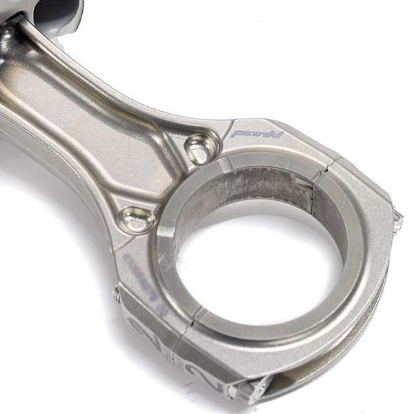
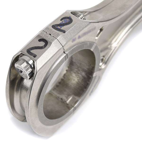
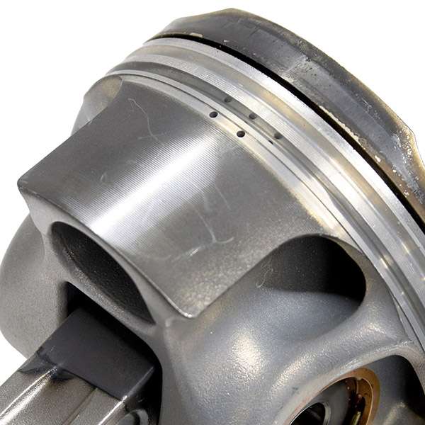
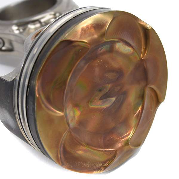
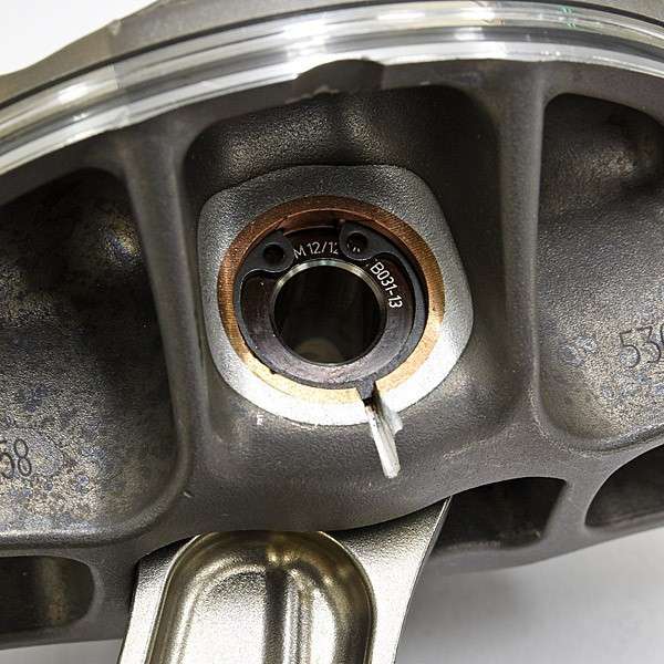
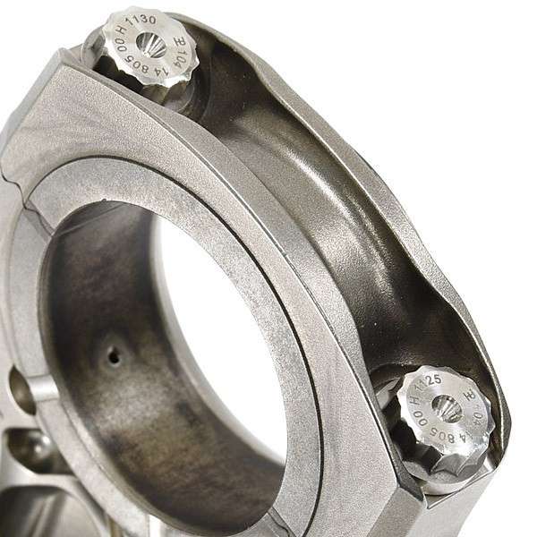
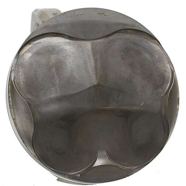
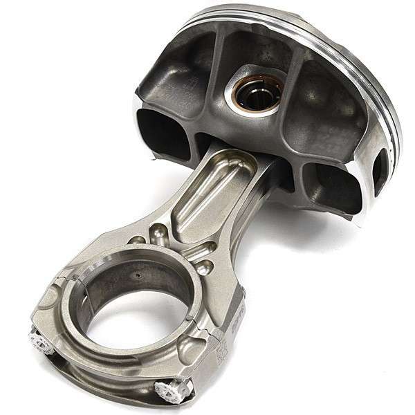
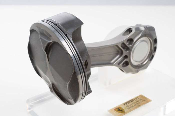
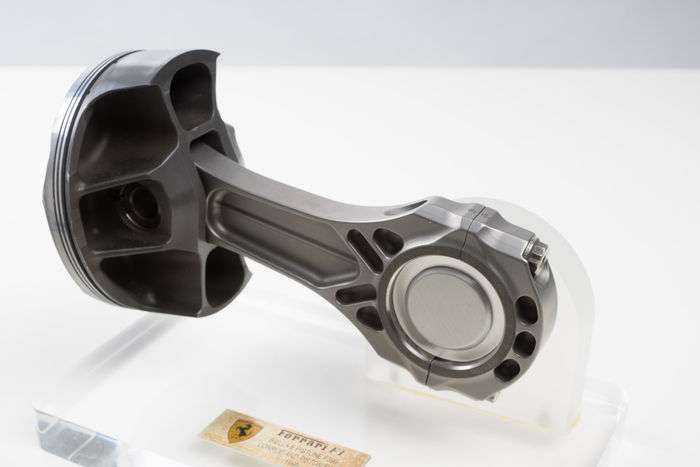
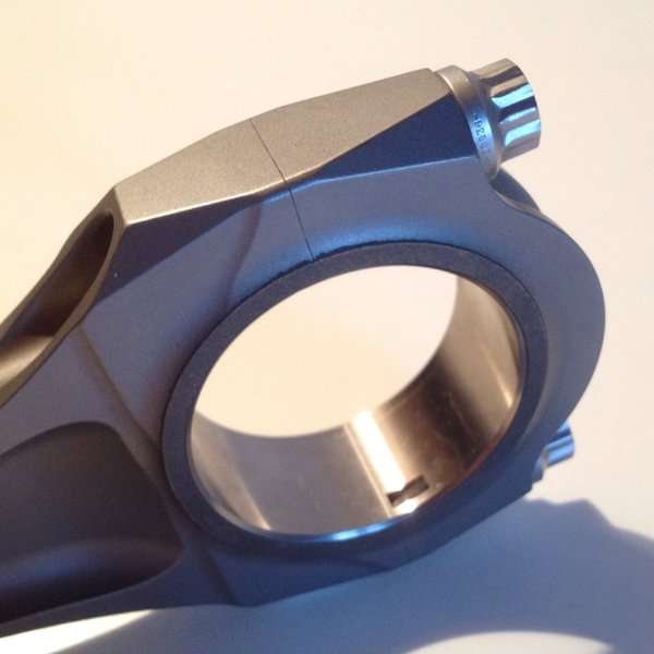
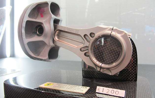
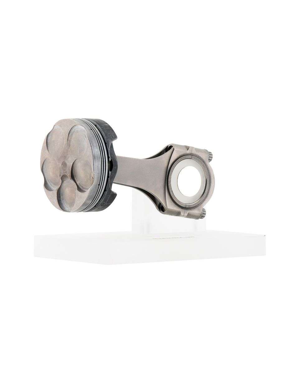
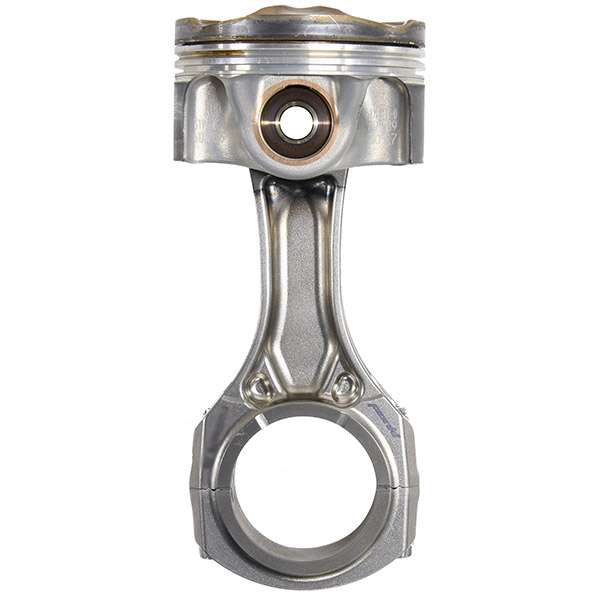
For reasons I can't explain I am really fascinated by F1 conrods. I run a Google search every few days with "F1 conrod" and look through the images to see what pops up. Yesterday was a BIG surprise when a current gen 1.6L V6 Ferrari rod and piston showed up at a Japanese collector site (www.italiazakka.co.jp/shop/20949-0-en.html) (All images are used without permission. If you want something removed please contact me and I will take it down.):

2014 - present, turbocharged 1.6L V6:
Image
Image
Image
Image
Image
Image
Image
Image
Image

2006 - 2013, normally aspirated 2.4L V8:

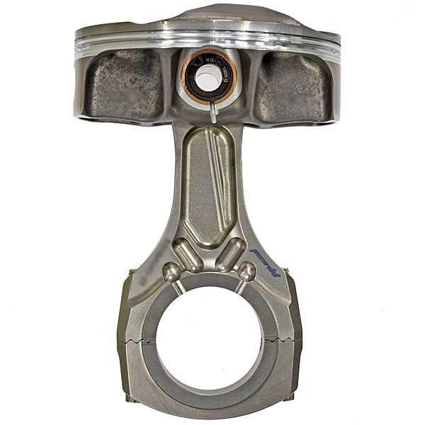
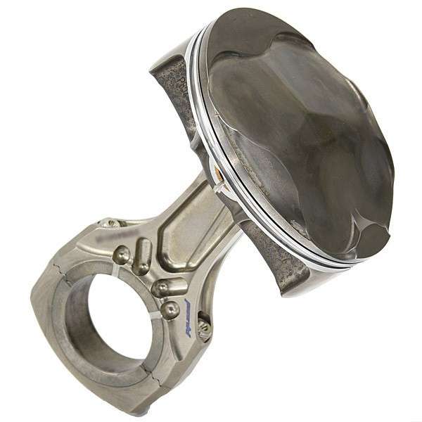
Ferrari V8, no date given: These resemble the last of their V10 rods quite a bit, but the caps have the more 'modern' serrated locating feature. The piston is also different: Check out the windowed skirt in the sixth image. I don't recall ever having seen that feature before.
Image
Image
Image
Image
Image
Image

Cosworth V8. Bottom version must have come first:
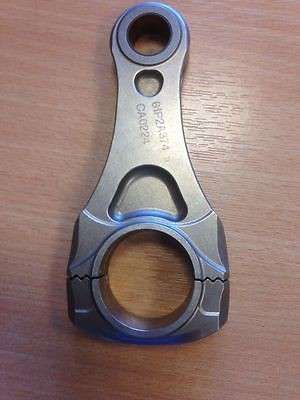
Image
Image
Image
Image

Honda V8, which never raced? Interesting that these are all labelled 6/4 Ti and not the more exotic powder metallurgy Ti used later (Sorry, can't remember the full name.). Note that the big end on the left rod below seems to have the same mystery surface treatment that the 1.6L rod and the later Cosworth V10 rods have on their small ends...
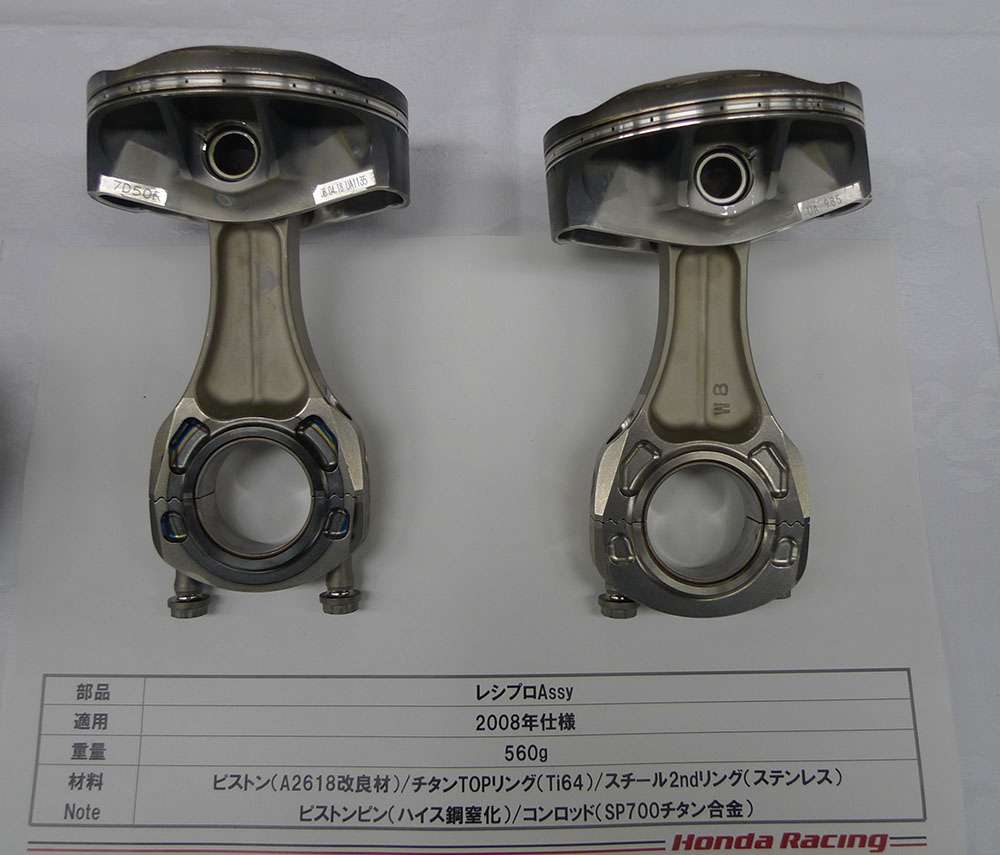
Image

2000 - 2005, normally aspirated 3.0L V10:

Peugot V10: The first two images MUST be the older design. The rods in the third image are surprisingly different than the Cosworth V10 versions shown below.
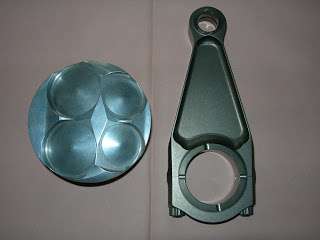
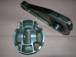
Image
Image
Image

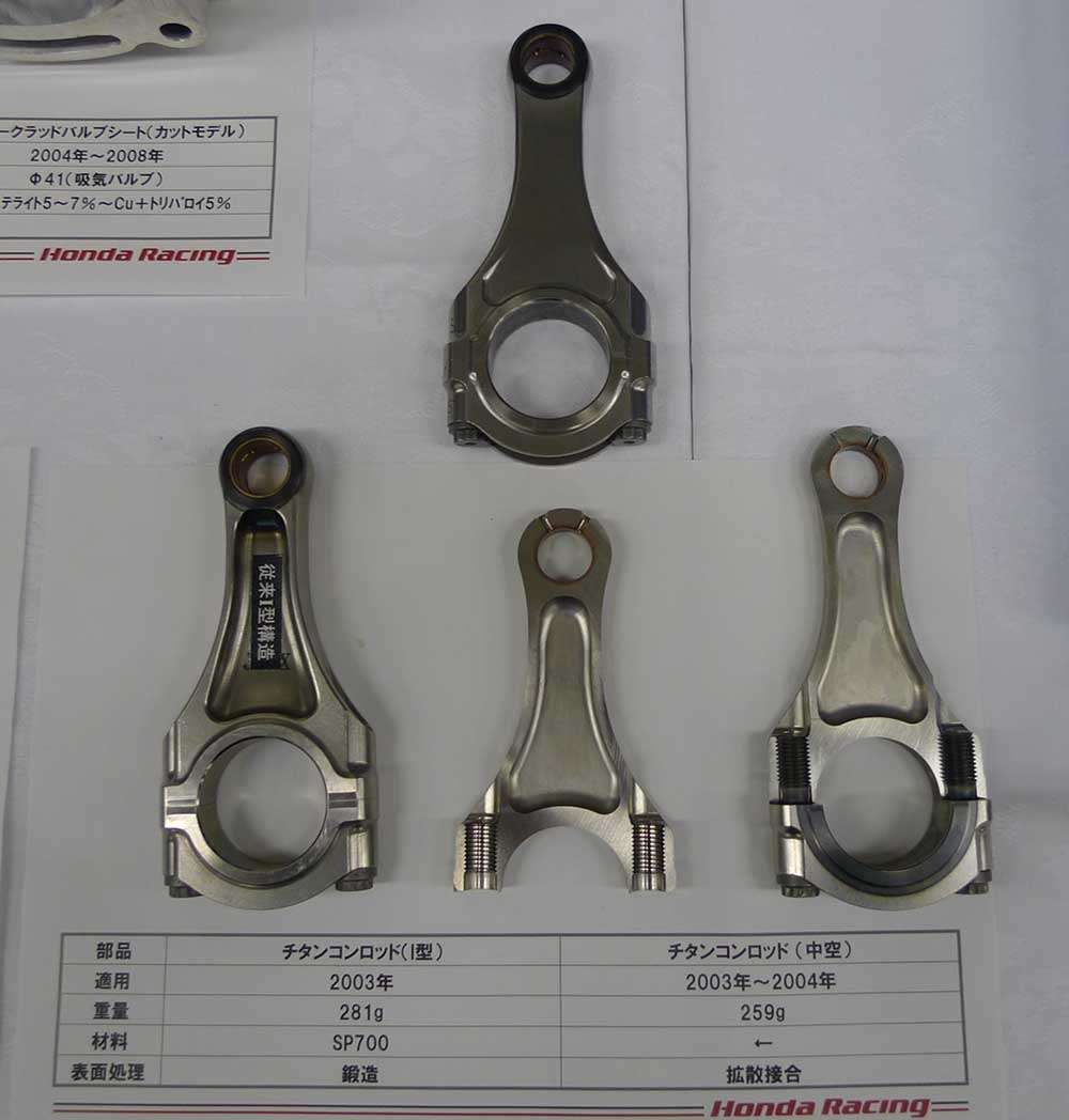
Honda V10: Nice research paper on the hollow rod effort here: http://www.f1-forecast.com/pdf/F1-Files ... P2_34e.pdf I don't think the hollow rods ever raced.
Image

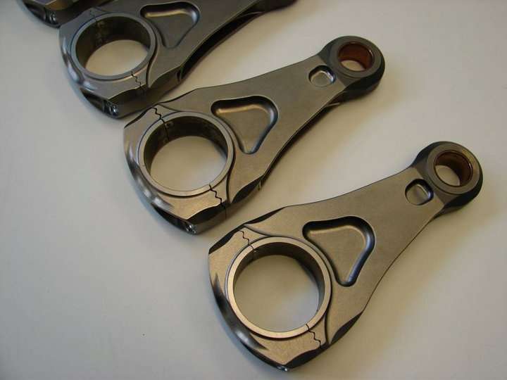
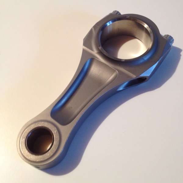
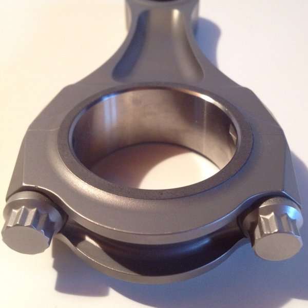
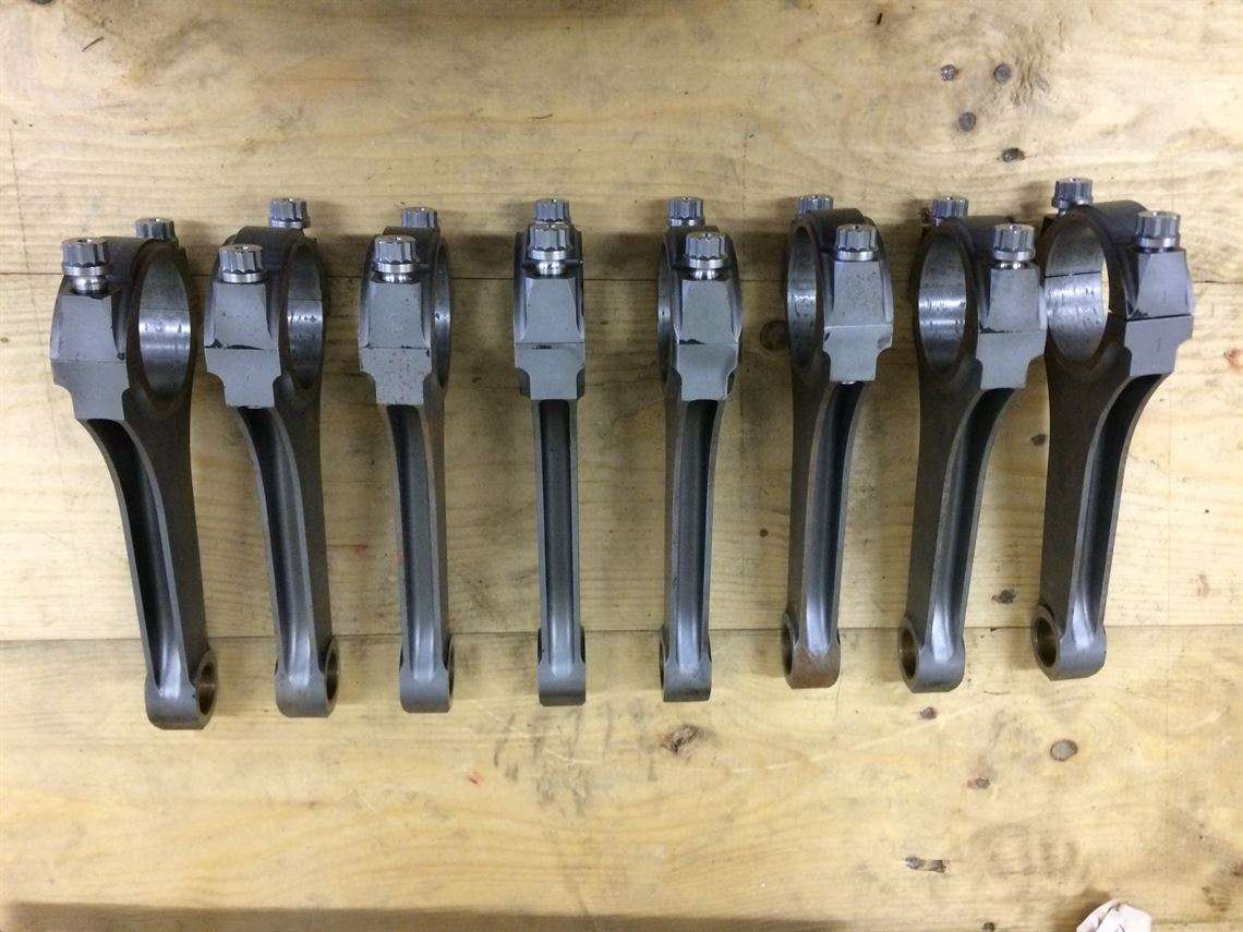
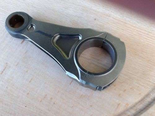
Cosworth TJ N.A. V10: The differences shown being either different vintages or different badged teams. This thread goes deep on the Cosworth TJ rod: viewtopic.php?f=4&t=9346&hilit=Pankl+Conrod. Note the difference in how the caps are machined, and how they are located. The piston is just to have something to compare to the 1.6L version above (I don't think anyone raced a full 'dlc' coated piston, so this seems like an experiment.).
Image

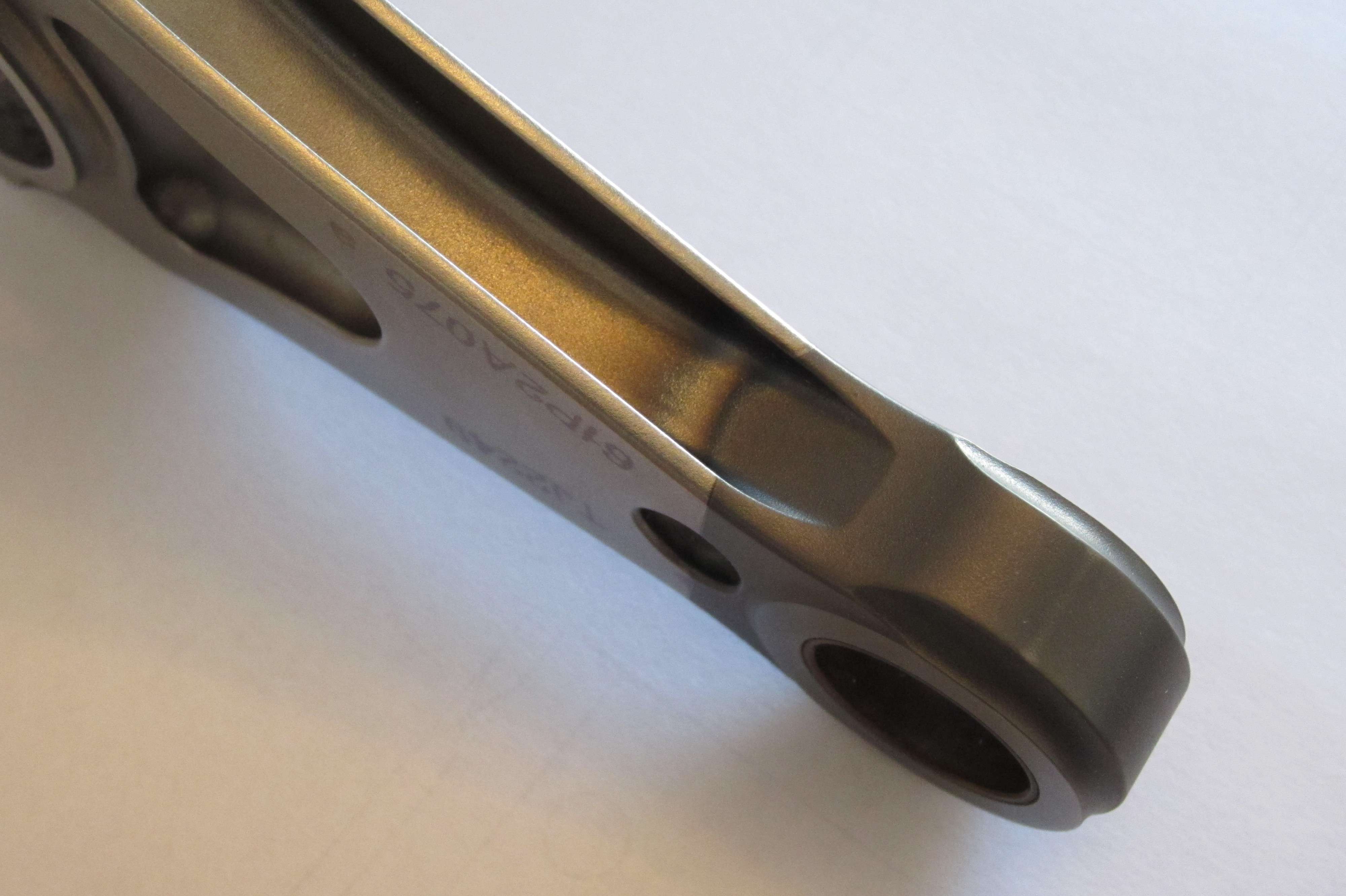
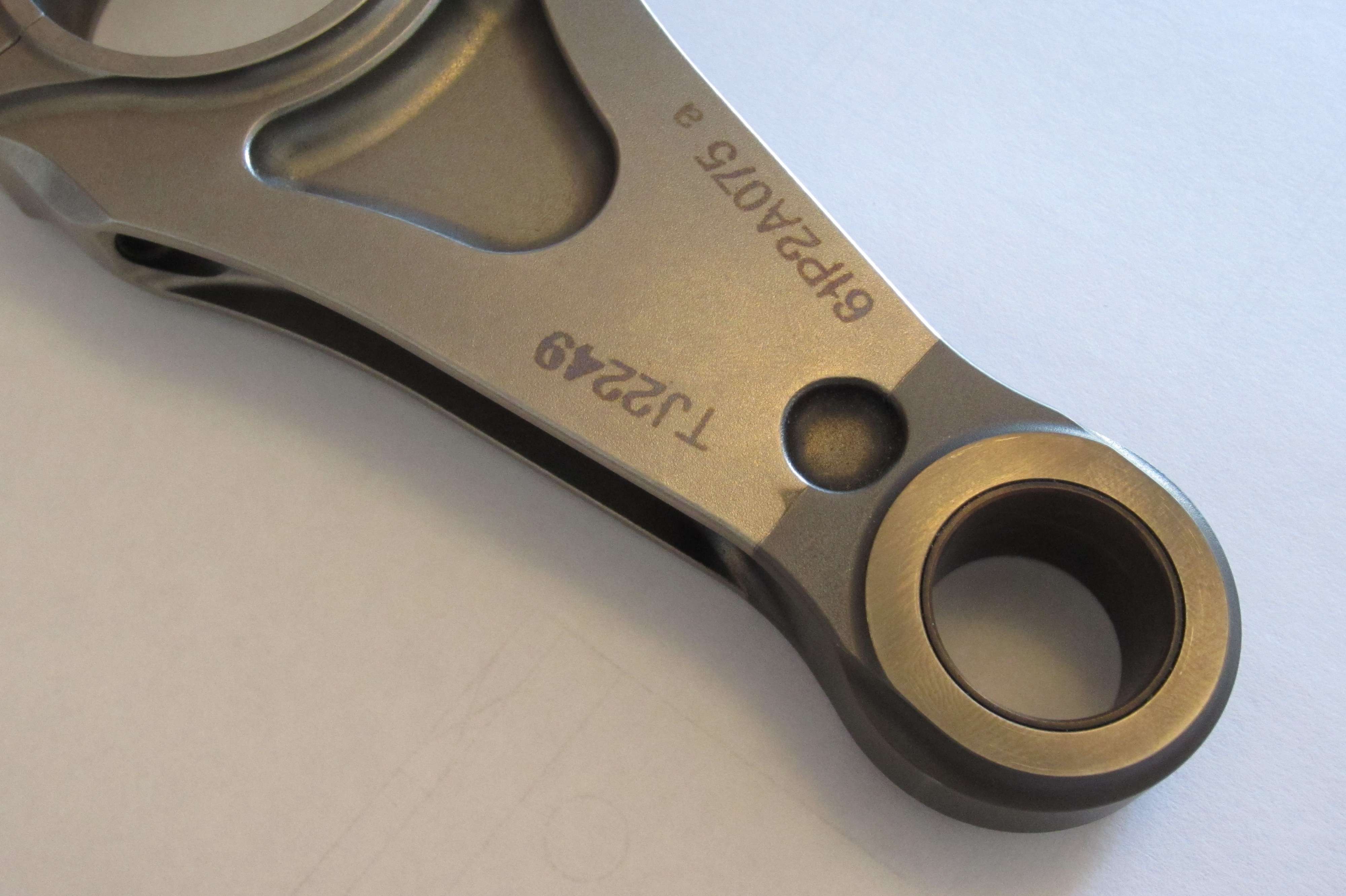
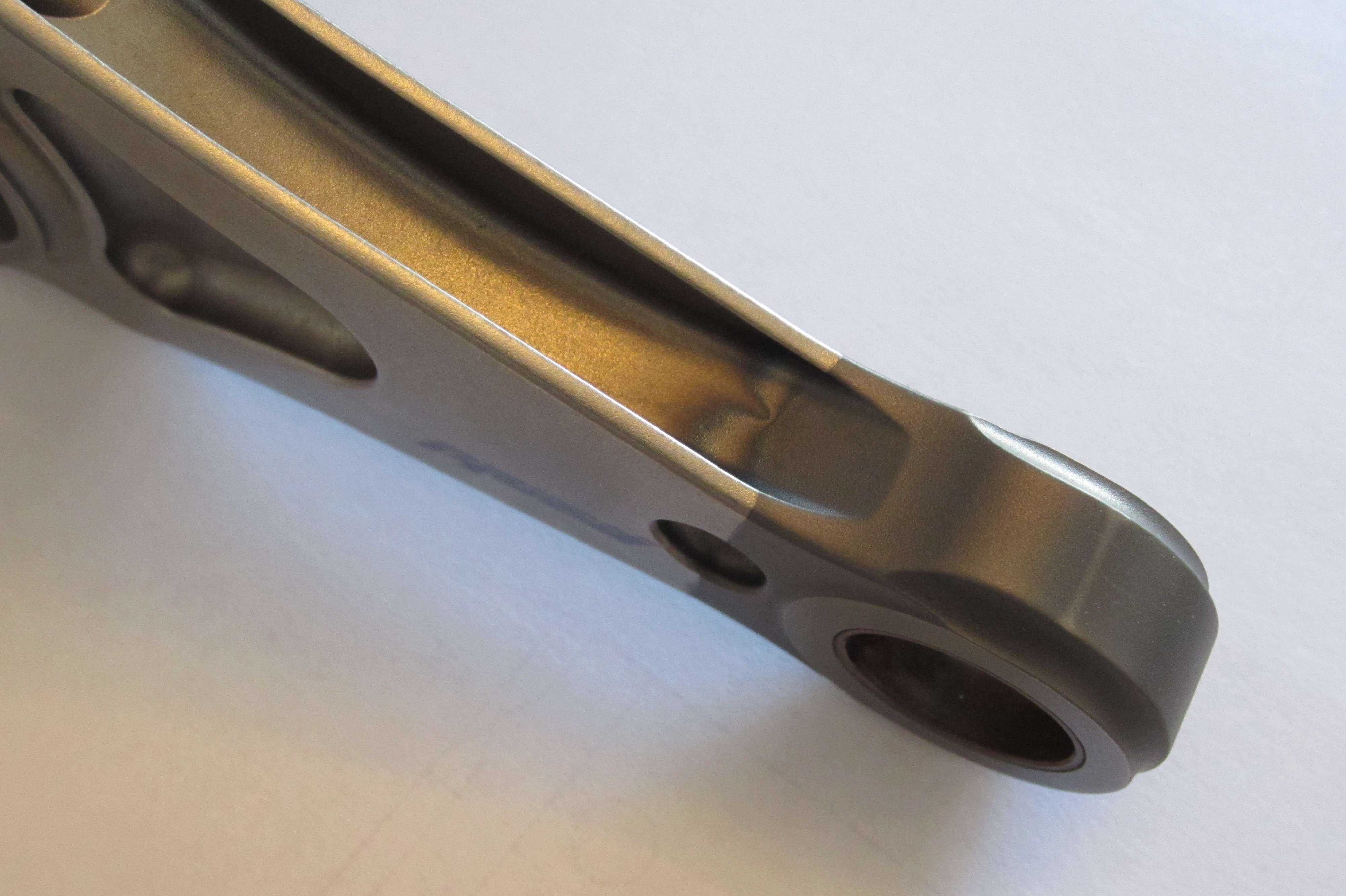
Here are some better images of the surface treatment applied to the small-end, presumably to eliminate galling when pressing the bushing in.
Image
Image
Image
Image
Image
Image

Ferrari F-399 V10 (1999): Not sure which version came first. Top version could be a cousin to the V6 rod above. These and the Honda rods are the only forced pin oiling examples:
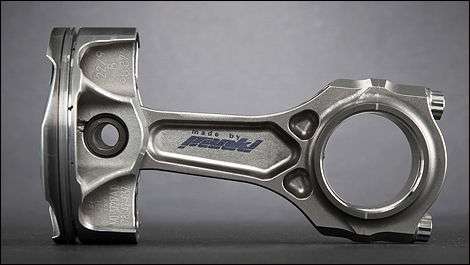
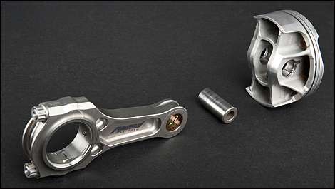
Image
Image
Image
Image

Ferrari F1-2000, N.A. 3.0L V10:

Image
Image
Image

Ferrari F-2003 V10:

Image

Ferrari F-2004 V10: Is the angled small end oiling about timing? This also seems like the first 'hybrid' geometry Pankl rod, part "I Beam" part "H Section":
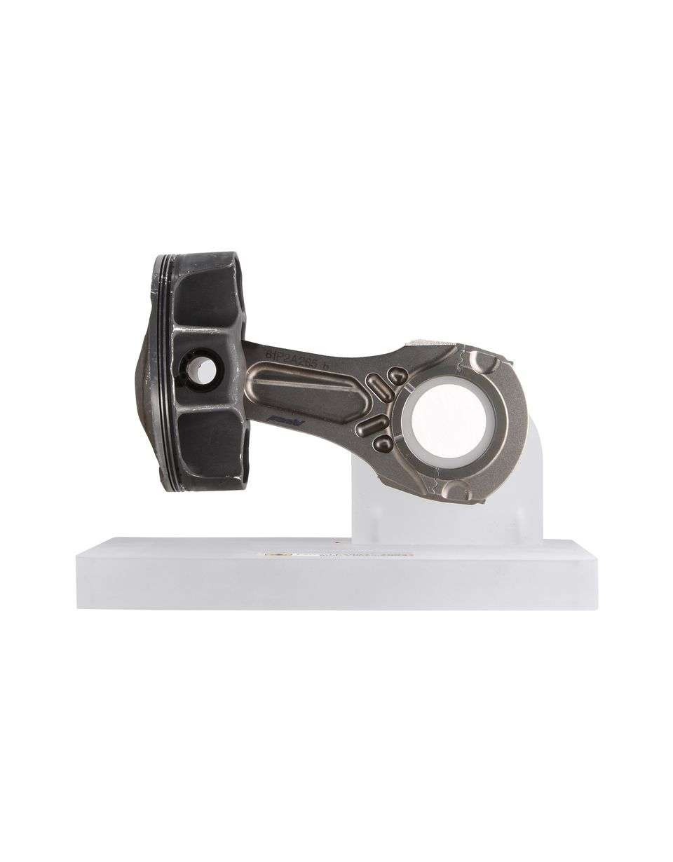
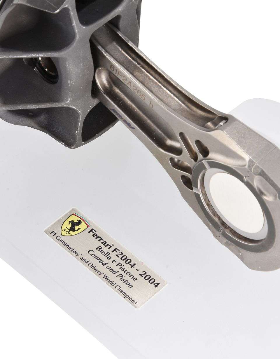
Image
Image

1986 - 2000, 1.5L Turbos, 3.0 L N.A., 3.5 L N.A.:


1992 Ferrari F92A, N.A. 3.5L V12: These look like steel.
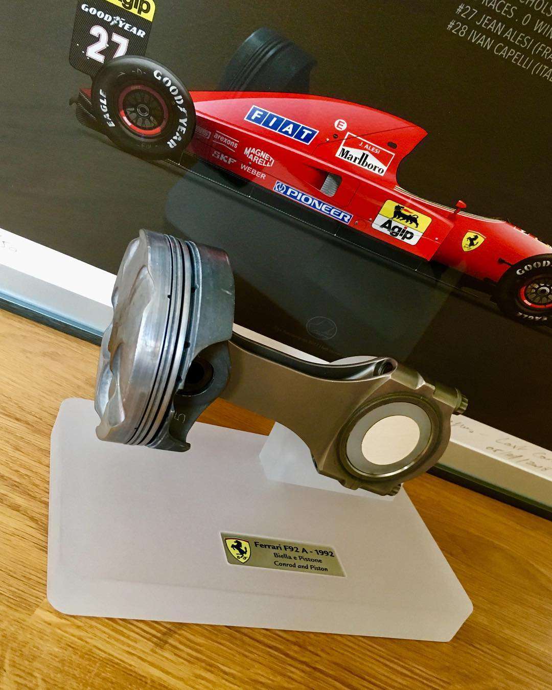
Image
Image

1984 - 1987 1.5L Turbo V6

TAG - Porsche: At the end of its development it was hitting 1,060 hp in quali mode, @ 12,600 rpm. Piston included for comparison to the current gen.
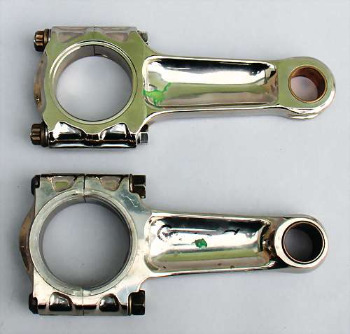
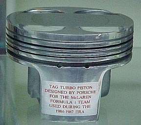
Image
Image

1967 - 1985, normally aspirated V8:

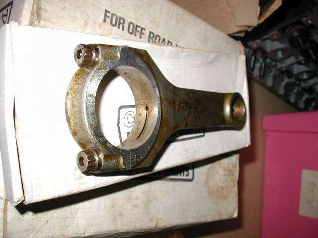
Cosworth DFV / DFR V8: These are steel. Note the 'balance' pad at the small end, just like most stock rods...
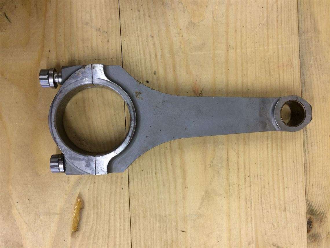
Image
Image
Image


Orphans: I can't link these to a year or car. Any info here greatly appreciated.

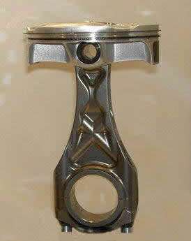
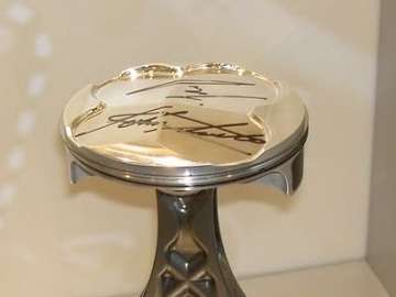
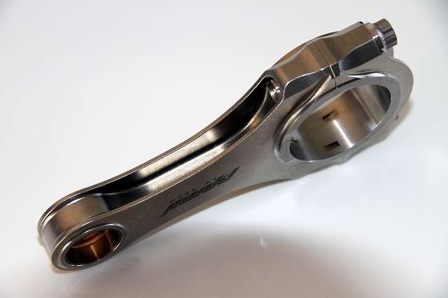
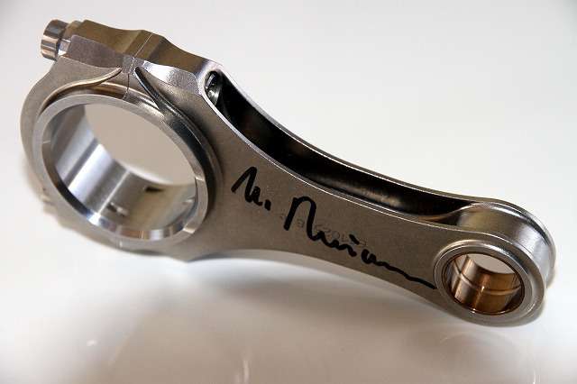
Pankl "Mystery Rod #1": I thought this was just a 'demo' piece, but the autograph on the piston makes me think it was 'real'. Lack of serrated cap location says 2005 or earlier vintage.
Image
Image
Image

Pankl "Mystery Rod #2": This one only shows up in their annual report. It may not be 'real'. The organic shape is sure a contrast to Mystery #1 above. Again, the lack of serrated cap location says 2005 or earlier vintage.


Image

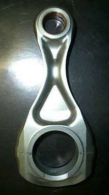
Pankl "Mystery Rod #3": This is also something from their annual report and again may not be 'real'. Interesting form though. Ditto for the lack of serrated cap location saying 2005 or earlier vintage.

Image

Pankl "Mystery Rod #4": This was on a Japanese collector site and is supposedly a BMW F1 piece, autographed by Dr. Mario Thiesen (spelling?). These look like steel to me. Again, the lack of serrated cap location says 2005 or earlier.
Image
Image


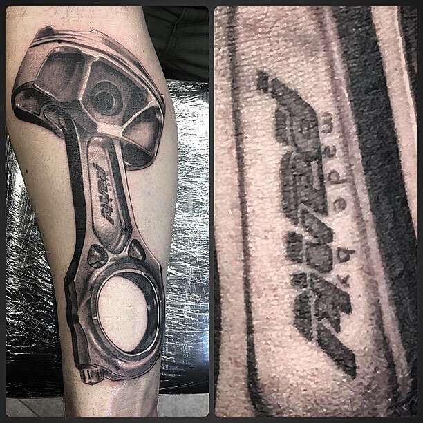
Lastly, for a laugh: Although I am clearly a Pankl fanboy, this is not me...
Image

Please chime in with insights and commentary. If you have more images please do share. I didn't intend for this to be a Pankl-fest, so please share other manufacturers if you have info.

Cheers,

Jon
Last edited by e36jon on 26 Jun 2018, 22:24, edited 26 times in total.

glenntws
glenntws
87
Joined: 15 Feb 2017, 15:41
Location: Germany

Re: F1 Conrods

Post

Hello,

you didn't upload the pictures correctly. I'm very curious about the ferrari piston and rod. Maybe you could check that again.

User avatar
rscsr
51
Joined: 19 Feb 2012, 13:02
Location: Austria

Re: F1 Conrods

Post

glenntws wrote:
13 Jun 2018, 18:34
Hello,

you didn't upload the pictures correctly. I'm very curious about the ferrari piston and rod. Maybe you could check that again.
When you quote a post, the links somehow become clickable.
e36jon wrote:
13 Jun 2018, 18:20
Greetings all

For reasons I can't explain I am really fascinated by F1 conrods. I run a Google search every few days with "F1 conrod" and look through the images to see what pops up. Yesterday was a BIG surprise when a current gen 1.6L V6 Ferrari rod and piston showed up at a Japanese collector site (All images are used without permission. If you want something removed please contact me and I will take it down.):

https://drive.google.com/open?id=1eqG0L ... rXQIY__p5W
https://drive.google.com/open?id=14wqb9 ... hBGU95O0t6
https://drive.google.com/open?id=1jjXlF ... DJQ5y-Qaqc
https://drive.google.com/open?id=1D2D3b ... ZoUGgm-nAS
https://drive.google.com/open?id=1hBXUR ... tPWRR6uPaf

The generation before looked like this, Cosworth V8:

https://drive.google.com/open?id=1X95Cy ... Je_ynkUiQJ

And before that the V10 era. These Peugot rods are surprisingly different than the Cosworth V10 versions we've seen here before:

https://drive.google.com/open?id=1Hx2vy ... wRtxIHypaG

Please chime in with insights and commentary. If you have more images please do share. I didn't intend for this to be a Pankl-fest, so please share other manufacturers if you have info.

Cheers,

Jon
glenntws
glenntws
87
Joined: 15 Feb 2017, 15:41
Location: Germany

Re: F1 Conrods

Post

Oh, thank you very much!

Ok so many interesting things...

- The wrist pin seems to swim at the contact points to the piston, otherwise I wouldn't understand why they would shrink in a bronze bearing in the piston.
- The rods are obviously waaay heavier than on he previous engines.
- Piston skirts are coated with Molybdenum or DLC, just as expected.
- It can be marks from the manufacturing process, but I think it's on purpose: The skirts are ribbed to reduce friction and allow oil to stay between skirt and the liner.
- I don't know if this is from a engine with pre-chamber technology, but it seems that the injector is centered and the spark plug also is very near to the center, but to be true I even think this is a pre-chamber piston. The sides of the piston are extremely high, they probably reach up to the cylinder head surface, they have the pre-chamber in the center and want to isolate the flame from the liners, just like expected. However, the burning marks are a bit contrary to the pre-chamber thing because it seems like flame propagation wasn't starting from the center.
- Two compression rings again, but that isn't surprising when you think about lower rpm and way more cylinder pressure.
- This piston is extremely strong built. It's obviously a aluminium piston but I would be pretty sure that they would use steel pistons. However, maybe they do now. The piston seems to be built for a peak cylinder pressure of more than 350 bars, maybe even more (it has been to long since I worked on my engine to get a good estimation just with looking at a piston :D )
- The valves are way smaller than with the 2.4 Liter engine, they are also extremely wide spaced, there is so much space for interesting technology in the center.

e36jon
e36jon
66
Joined: 25 Apr 2016, 02:22
Location: California, USA

Re: F1 Conrods

Post

Thanks for all of the insight glenntws!

I just added the last few images from the Japanese site. One thing I noticed is some new-to-me machining for locating the rod cap. Wish they had opened that joint up, which is greedy given all that they did show. Anyone ever see the machining in question before? Any images of what that looks like 'open'?

I agree the piston may be the more interesting piece here. I thought 'diesel' when I first saw it, which is seemingly true some of the time... Looking at the valve pockets it looks like the valve layout is 'radial', or inclined in two planes. That's a pain for cams and followers and such, so given the higher required mileage these engines will see I wonder what the payoff is? In the past, with normally aspirated engines, you could pick up some flow, and maybe a 'better' combustion chamber, but with forced induction it doesn't seem as obvious to me.

Looking forward to more comments...

Jon

63l8qrrfy6
63l8qrrfy6
368
Joined: 17 Feb 2016, 21:36

Re: F1 Conrods

Post

Thank you Jon, great stuff.

I have been designing high performance rotating and reciprocating engine components for quite a while and I've had the chance to work closely with Pankl. I'd also worked at Mahle for a few years, mainly at their site in Rugby (which used to be Vandervell bearings) and mainly on motorcycle engines.

I am a bit suspicious regarding the authenticity of the Ferrari V6 bits, however having visited the Mercedes restaurant at their engine site in Brixworth where they have a V6 turbo piston on display I have to say that the proportions look spot on. Unfortunately the Merc piston is positioned such that only the crown, skirts and pin bores are visible, so no clue what it looks like from below.

The (allegedly) Ferrari piston looks outstanding and the complexity of the oil pockets/gallery is impressive, even though it means that the piston cannot be forged. At the same time I am surprised about the poor finish given that even older F1 V10/V8 pistons had very well finished under-crowns. I think Cosworth VJ was Ra 0.8 or so.

The wear pattern on one of the skirts (presumably thrust side) does not look right, with signs of contact at the sides and bottom edges. There does not appear to be any visible sign of land contact which is commendable given that the piston looks quite top heavy and runs at high speed and high cylinder pressure. It could be that the lands are cut-back aggressively (which is bad for crevice volumes at the top land, particularly with what appears to be a very low compression ring).
The compression height is quite large which is why I was saying the the piston appears top heavy. In addition there's rumors that Ferrari have started using a steel crown insert after their failed attempt at 3D printed steel pistons. It's hard to tell because of the carbon deposits and the crown coating (which seems to be some form of ceramic thermal barrier). The skirt coating is most definitely not DLC (it is known to weaken piston skirts) but rather some form of moly/graphite. Since it is known Mahle have been involved, I would put my money on their proprietary graphal. By contrast Cosworth have always sworn by their green Xylan coating.

No accumulation grooves visible on the second land (probably not needed with aggressive cut back) and more interestingly - no visible top groove gas ports.
Gudgeon pin is most likely DLC coated with a straight bore. It is not uncommon to profile the pin ID to help balance the pin stresses, so I am a bit surprised by that. But then again, Cosworth used to run a straight bore pin at over 20k RPM so maybe it's not necessary.
Notably the circlip has nicely rounded ends so that it does not dig into its groove. The bronze bushing is fairly standard and I would expect there to be one in the small end too.

Onto the mystery of the rod serrations - these are perpendicular serrations designed to prevent both lateral and axial relative movement. It is a proprietary Pankl design as far as I am aware.
Titanium has very poor tribological properties and is therefore very susceptible to fretting and galling. It is also hard (if not impossible) to fracture split so the only available options for preventing relative movement between rod and cap are serrations. F1 V8 engines relied on standard axial serrations and dowels (standard ones rather than the more common ring dowels). It is now believed that dowels are not particularly effective at stopping axial relative motion.

The "elephant in the room" is the heat discoloration around the small end - can't really work out what is going on there but that doesn't look as something that should ever run in an engine!
Interestingly the rod thrust faces have bearing oil drain grooves in them which is indicative of a crank guided rod. Traditionally F1 engines have used piston guided rods since the friction torque is smaller (due to the smaller contact radius at the small end thrust face) so rods have not required drain grooves since there was always clearance between the crank shoulder and rod face. Again the coating on the rod thrust faces seems to be moly based as usual.

The rough looking big end bore surface is a testament of the poor tribological properties of titanium. It was common in the V8 days for rods to fail from fretting initiated between the back of the bearing and rod, particularly with steel-backed big end bearings which prompted some manufacturers to start using plain bronze bearings. These tend to be better at dissipating heat generated in the bearing at the expense of a higher coefficient of thermal expansion compared to titanium. (Steel CTE is much closer to Ti than bronze).

A very important feature that Pankl are very particular about is the large fillet around the thread break-out. The last engaged thread is exposed to the highest alternating stress and the fillet is designed to improve the fatigue life of that region.

The rod cap parallel ribs are a dated feature that I do not agree with since it tends to over-stiffen the bearing edges. A better design in my view is ribs that converge into a single rib towards the middle of the cap (Pankl also offer this).

Overall the rod big end looks pretty flimsy compared to old V8 rods. Given that titanium has half the steel's Young's modulus, I would have expected the big ends to be really beefy.
Last edited by 63l8qrrfy6 on 13 Jun 2018, 23:36, edited 2 times in total.

User avatar
strad
117
Joined: 02 Jan 2010, 01:57

Re: F1 Conrods

Post

Thanks for the insight.
To achieve anything, you must be prepared to dabble on the boundary of disaster.”
Sir Stirling Moss

e36jon
e36jon
66
Joined: 25 Apr 2016, 02:22
Location: California, USA

Re: F1 Conrods

Post

Thanks for the detailed reply Mudflap. Really awesome to have you here...

To build on a few things you mentioned:

1) The heat discoloration at the small end of the 1.6L rod looks like the surface treatment on the Pankl Cosworth TJ rod that I have. You can see it in the first image for the Cosworth V10 rods above. Are you seeing heat discoloration above and beyond this surface treatment?

2) I was also surprised at the straight-bore wrist pin. Not unusual, but with the F1 crowd I always imagine every gram having a target on its head.

3) My TJ rod was run, and like 1.6L rod the inside of the big-end bore is not pretty. I also have the 'early' version with pin-location for the cap and the tall paralell stiffening skirts on the cap.

4) The serrated cap location is used by lots of manufacturers, so I have seen it in some detail. The 'best' one was a circular groove pattern when viewed normal to the mating face as that seemed like it would handle two axis instead of just one. Any idea where I might see the proprietary Pankl pattern? For instance, I know Ducatti run their rods in their top spec sport bike...

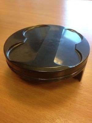
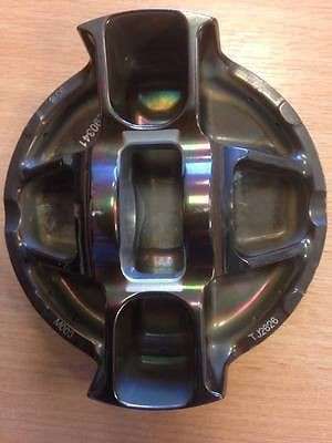
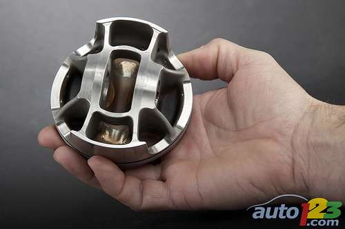
5) A piston question: On the TJ piston (Example below, with hand cut windows.) and the 1.6L piston there are windows cut into the 'bridges' on either side of the pin, between the underside of the dome up into the bridge. On the TJ piston I assumed for weight reduction, but the 1.6L piston is a beast so that doesn't seem like the reason. Thoughts?
Image

Sorry to reward your great post with a bunch more questions!

Jon

gruntguru
gruntguru
566
Joined: 21 Feb 2009, 07:43

Re: F1 Conrods

Post

Mudflap wrote:
13 Jun 2018, 23:00
Overall the rod big end looks pretty flimsy compared to old V8 rods. Given that titanium has half the steel's Young's modulus, I would have expected the big ends to be really beefy.
Great post Mudflap.

The need for big-end strength is perhaps more closely related to rpm than power or specific power. The V6 turbo engines are much lower revving and also see much less negative force at TDC exh due to high gas pressure.
je suis charlie

J.A.W.
J.A.W.
109
Joined: 01 Sep 2014, 05:10
Location: Altair IV.

Re: F1 Conrods

Post

Cool finds there e-jon, ta..

About the piston in the 1st post.. ok, you've confirmed the 'radial 4V' speculation ( discussed here recently).
but is that comp-chamber face.. golden top-coat - a thermal insulator, calalytic-burn interface, deto-resistor.. or all 3?

& the top ring land zone is interesting.. as is the very slender (absent its Napier 'wedge' type ring?) - ring fit..

For sure the smoothly 'organic' piston shape is self-evidently - a robust/durable form..

& g-g is - as usual - correct about the conrod functional design parameters..
For super high rpm light alloys have inherent elastic 'give'.. at the price of a shorter TBO - 'life'..
"Well, we knocked the bastard off!"

Ed Hilary on being 1st to top Mt Everest,
(& 1st to do a surface traverse across Antarctica,
in good Kiwi style - riding a Massey Ferguson farm
tractor - with a few extemporised mod's to hack the task).

e36jon
e36jon
66
Joined: 25 Apr 2016, 02:22
Location: California, USA

Re: F1 Conrods

Post

Greetings J.A.W., it's great to have you here.

I would point you at the excellent post by Mudflap for all of your answers (Please note his employment credentials at the start of his post. He seems credible!):

1) Crown finish:
It's hard to tell because of the carbon deposits and the crown coating (which seems to be some form of ceramic thermal barrier).
He also mentions that if this is real it's certainly not current, as efforts all around are to use steel / something other than aluminum.

2) Regarding ring fit / land geometry:
There does not appear to be any visible sign of land contact which is commendable given that the piston looks quite top heavy and runs at high speed and high cylinder pressure. It could be that the lands are cut-back aggressively (which is bad for crevice volumes at the top land, particularly with what appears to be a very low compression ring).
and
No accumulation grooves visible on the second land (probably not needed with aggressive cut back) and more interestingly - no visible top groove gas ports.
Would appreciate a link to the radial valve discussion as I missed it. Ditto for letting me know if all of this is being discussed elsewhere. If it doesn't show up on the main page in the active topics I am probably not aware of it.

Cheers,

Jon

User avatar
godlameroso
309
Joined: 16 Jan 2010, 21:27
Location: Miami FL

Re: F1 Conrods

Post

glenntws wrote:
13 Jun 2018, 18:57
Oh, thank you very much!

Ok so many interesting things...

- The wrist pin seems to swim at the contact points to the piston, otherwise I wouldn't understand why they would shrink in a bronze bearing in the piston.
- The rods are obviously waaay heavier than on he previous engines.
- Piston skirts are coated with Molybdenum or DLC, just as expected.
- It can be marks from the manufacturing process, but I think it's on purpose: The skirts are ribbed to reduce friction and allow oil to stay between skirt and the liner.
- I don't know if this is from a engine with pre-chamber technology, but it seems that the injector is centered and the spark plug also is very near to the center, but to be true I even think this is a pre-chamber piston. The sides of the piston are extremely high, they probably reach up to the cylinder head surface, they have the pre-chamber in the center and want to isolate the flame from the liners, just like expected. However, the burning marks are a bit contrary to the pre-chamber thing because it seems like flame propagation wasn't starting from the center.
- Two compression rings again, but that isn't surprising when you think about lower rpm and way more cylinder pressure.
- This piston is extremely strong built. It's obviously a aluminium piston but I would be pretty sure that they would use steel pistons. However, maybe they do now. The piston seems to be built for a peak cylinder pressure of more than 350 bars, maybe even more (it has been to long since I worked on my engine to get a good estimation just with looking at a piston :D )
- The valves are way smaller than with the 2.4 Liter engine, they are also extremely wide spaced, there is so much space for interesting technology in the center.
You can clearly see the flame propagation is from the edge of the bowl inward, and you can see this is because the highest concentration of coloration is in the center. In normal combustion methods the coloration is at the piston edges. One thing I found impressive is how well that top ring seals, I don't see any blowby whatsoever.
Saishū kōnā

e36jon
e36jon
66
Joined: 25 Apr 2016, 02:22
Location: California, USA

Re: F1 Conrods

Post

Greetings all

I put up the last of the images I have in the first post. If you have something that's not there, or additional images, please put them up!

Also, with all the newness I have additional questions about which version came first, etc. As ever, your collective wisdom would be appreciated in getting my facts sorted.

Cheers!

"Hi, my name is Jon and I have a conrod problem..."

63l8qrrfy6
63l8qrrfy6
368
Joined: 17 Feb 2016, 21:36

Re: F1 Conrods

Post

e36jon wrote:
14 Jun 2018, 01:15
1) The heat discoloration at the small end of the 1.6L rod looks like the surface treatment on the Pankl Cosworth TJ rod that I have. You can see it in the first image for the Cosworth V10 rods above. Are you seeing heat discoloration above and beyond this surface treatment?
The "rainbow" pattern at the interface between the coated portion of the small end and the uncoated shank does not look right. The most common small end coatings are CrN (with deposition temperatures of max 350°C which I've never seen to change Ti color to such an extent) and various Mo compounds with deposition temperatures of about 150°C. TiN has also been used (goldy looking, not the case for this particular rod) and it has similar deposition temperatures to CrN.
e36jon wrote:
14 Jun 2018, 01:15
4) The serrated cap location is used by lots of manufacturers, so I have seen it in some detail. The 'best' one was a circular groove pattern when viewed normal to the mating face as that seemed like it would handle two axis instead of just one. Any idea where I might see the proprietary Pankl pattern? For instance, I know Ducatti run their rods in their top spec sport bike...
No idea, sorry, probably not in production engines anyway. Pankl tend to offer their customers very similar products so I would not be surprised at all if this joint turned out to be common across most F1 manufacturers.

e36jon wrote:
14 Jun 2018, 01:15
5) A piston question: On the TJ piston (Example below, with hand cut windows.) and the 1.6L piston there are windows cut into the 'bridges' on either side of the pin, between the underside of the dome up into the bridge. On the TJ piston I assumed for weight reduction, but the 1.6L piston is a beast so that doesn't seem like the reason. Thoughts?

The main purpose (if not the only one) is to provide oil access to the underside of the crown. Every square millimeter is very precious in managing the temperature of Al pistons. This task becomes very difficult when thick ribs get in the way and is another reason why I think steel pistons have an advantage. Even though the heat transfer coefficient is much poorer, the larger wetted undercrown surface (thinner ribs) and higher temperature fatigue strength more than make up for it.

Looking at the the skirt and pin pockets it is obvious that great effort was put into providing good oil access to the undercrown. The entire underside of the piston is saturated by multiple nozzles - at least one per pocket.

In my opinion that "windowed" rib parallel to the pin axis is not really necessary. The main bending load is about the pin axis and is taken by the ribs supporting the skirt, not the ribs perpendicular to them. As long as the small splayed gusset ribs are well designed to stiffen the pin bore the "windowed" rib (I think it is sometimes referred to as a T rib) is not required.

User avatar
godlameroso
309
Joined: 16 Jan 2010, 21:27
Location: Miami FL

Re: F1 Conrods

Post

You think the green is some chlorine compound, maybe combustion residual?
Saishū kōnā