Specifications of 50 famous racing engines up to 1994

All that has to do with the power train, gearbox, clutch, fuels and lubricants, etc. Generally the mechanical side of Formula One.
User avatar
hollus
Moderator
Joined: 29 Mar 2009, 01:21
Location: Copenhagen, Denmark

Re: Specifications of 50 famous racing engines up to 1994

Post

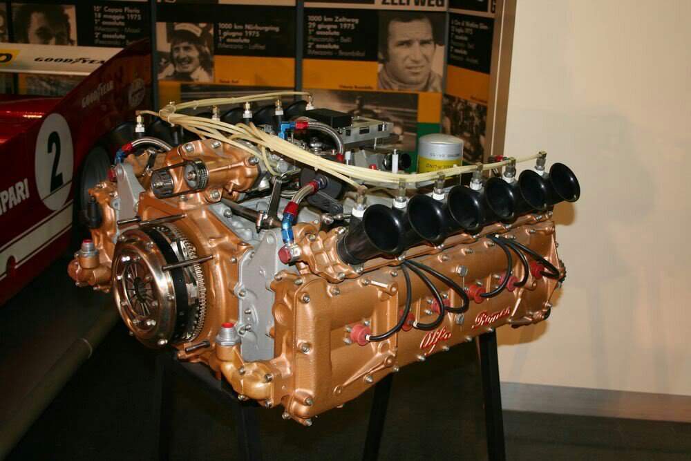
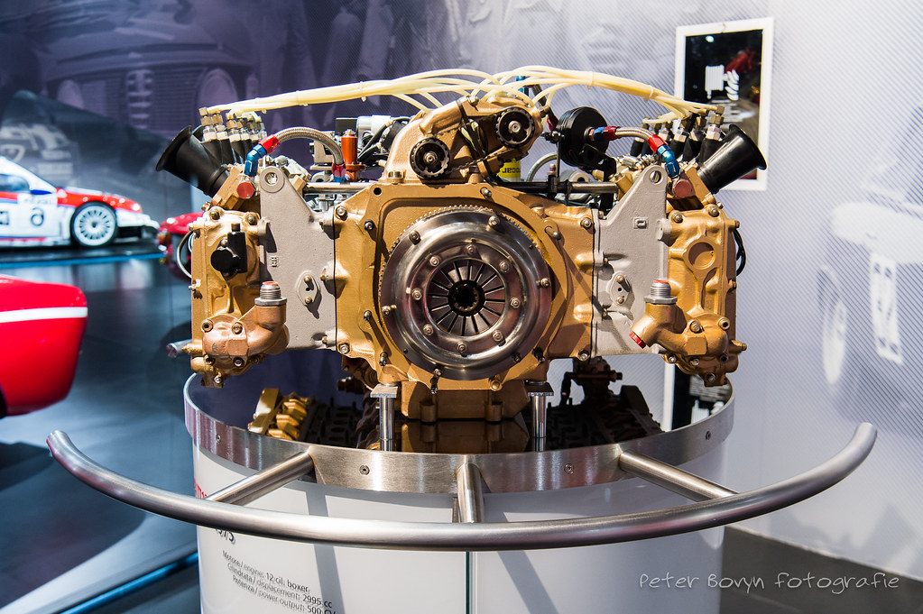
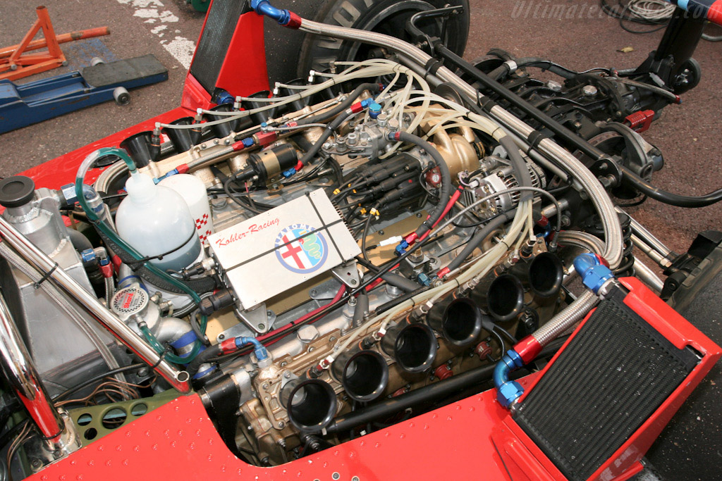
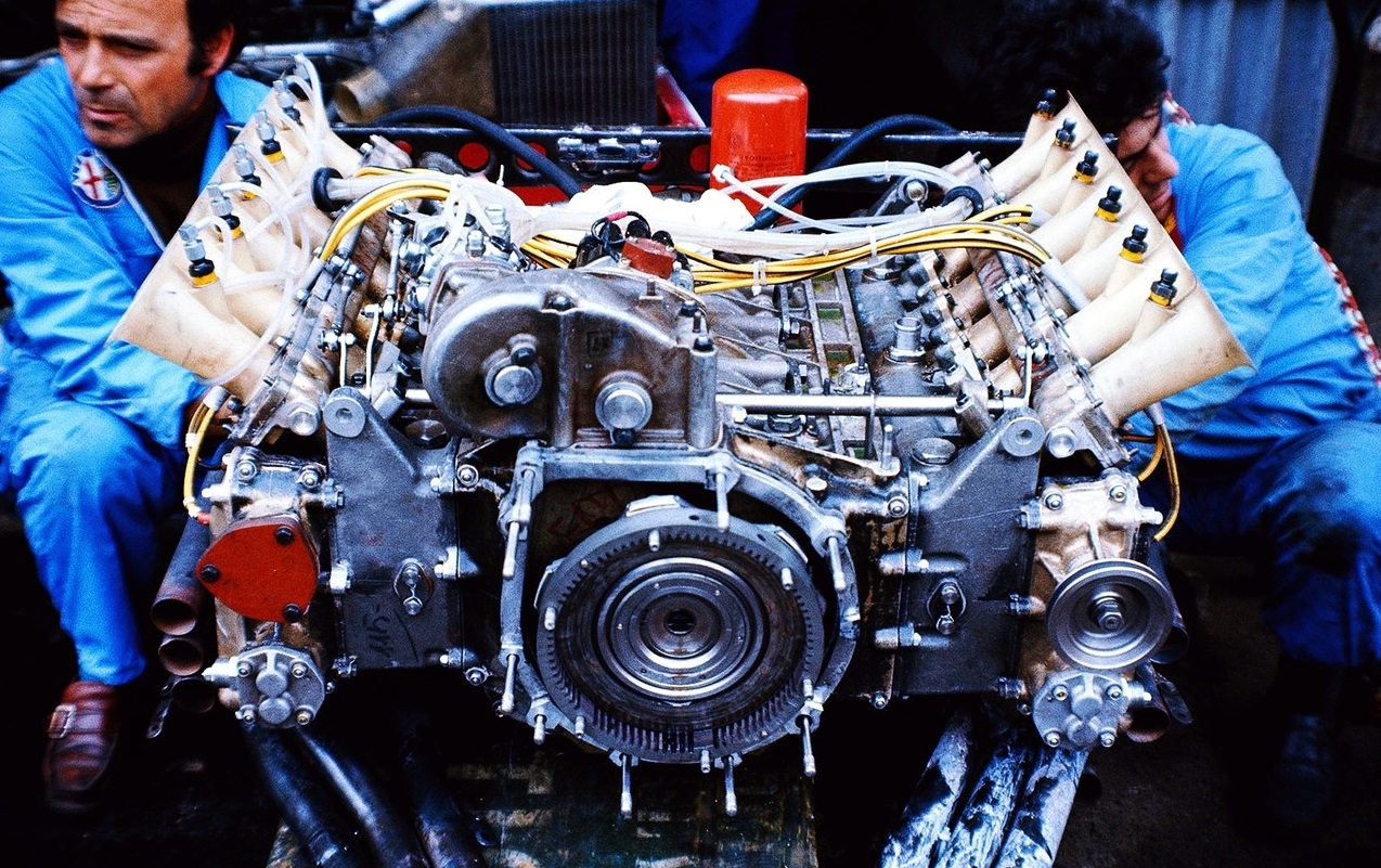
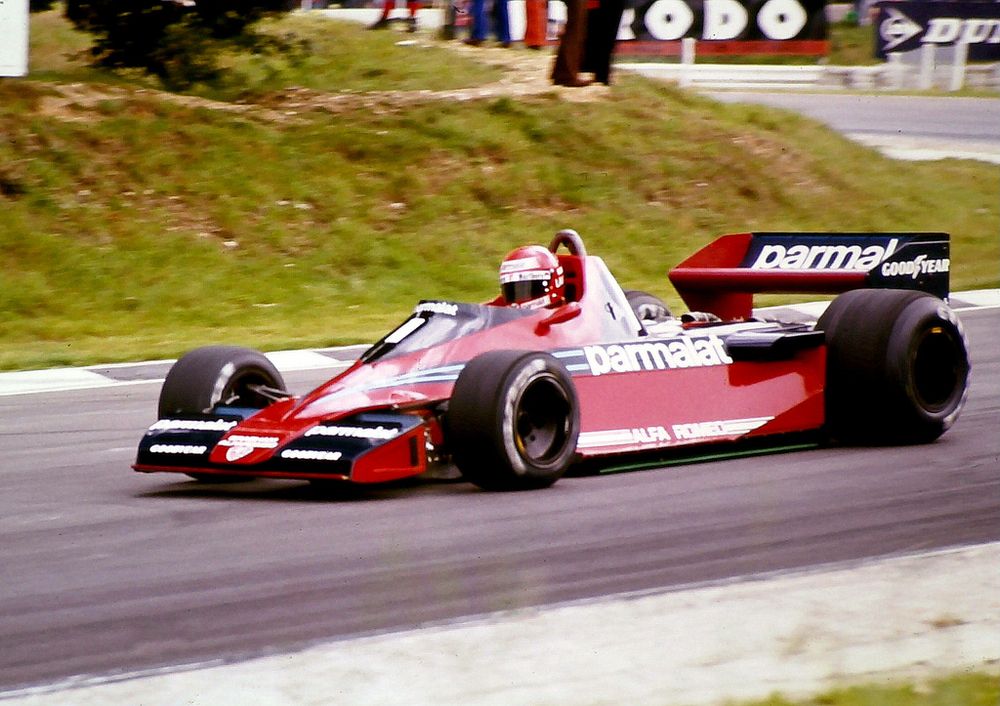
1975 Alfa Romeo 115-12 3-litre FLAT-12

1975 Alfa Romeo 115-12 3-litre FLAT-12. Alfa Romeo sports-prototype racing GT category successes in the 1960-1964 lured former Alfa Romeo engineer Carlo Chiti to the fold. Encouraged by Alfa’s enthusiastic chief Giuseppe Luraghi, Chiti in 1964 founded a new company near Milan, Autodelta, to develop and race cars for Alfa Romeo. Engineering for Autodelta’s projects was carried out by Chiti’s team with the blessing of Alfa engineers Orazio Satta and Giuseppi Busso.
Taking the sports-car racing category seriously, Chiti decided to build a completely new car for it, the type 33TT3. This had a tubular space frame, and its gearbox was located between the engine and the final drive. Although this first raced with a 3-litre V8 engine, a new flat-12 was being built to suit it. Thus-equipped the car became the 33TT12. First raced in 1973, by 1974 the new car was mature enough to win the 1000km’s of Monza. In 1975 the 33TT12 won the world championship of makes for Alfa Romeo. For 1977 Autodelta build a new chassis, the 33SC12, with aluminum monocoque frame. This was faster qualifier and winner of all 8-rounds of the makes world championship against modest opposition.
The Alfa flat-12 was rated at 470bhp@11000rpm at its launch in 1973, and at 490bhp@11500rpm in 1974 with 240lb/ft of torque@9000rpm. By mid-1975 with a compression ratio of 11:1, its peak output was a very impressive 526bhp@12000rpm with a power curve giving in excess of 400bhp from 9000rpm upwards. These were heady figures indeed in 1975, the year when another Italian flat-12 powered Niki Lauda to a Formula 1 world championship.
Indeed no one at that time was claiming a higher output from a 3-litre un-supercharged engine. Bernie Ecclestone, then owner of Brabham, negotiated with Alfa Romeo to gain exclusive use of their engine for his team from 1976. The flat-12 was raced by Brabham from 1976 to 1978 in cars designed by Gordon Murray. The first year was difficult, the second less so and in the third a number of good placings were achieved plus 2-victories for Niki Lauda at Sweden's Andersdorp and Italy's Monza. The Andersdorp victory was with the controversial 'fancar' Brabham, which used a 'cooling' blower to add downforce, the concept was banned after the race.
In designing the Brabham, Murray was challenged by the flat-12’s size and weight. It was, first of all, massive. Its weight in endurance-racing form was a substantial 178kg, some 10% more than most GP engines of the same displacement. In its GP version the 12’s weight was reduced to 175kg. It was also wide, wider than the flat-12 engine fielded by Ferrari. One reason for this was its longer stroke. Its cylinder dimensions were 77mm x 53.6mm for 2995cc, the Ferrari stroke was only 49.6mm in its final form. Another reason was that its inverted-cup-type cam followers were placed above its twin coil valve springs instead of being made large enough in diameter to shroud the valve springs. This effected a vital saving of mass in the follower, helping the engine reach its high speeds, but at a cost in engine weight and width.
It had 4-valves per cylinder, measuring 33mm for the inlets and 28mm for the exhaust. The endurance racing engines had 30mm inlets and 25.5mm exhaust valves. The valves were inclined at a narrow included angle of 27 degrees, 13 degrees for the inlets and 14 degrees for the exhaust. And had very long stems above the springs to allow the inlet port to enter the cylinder at the shallow angle of 38 degrees to its centerline. Previously the valves were alloy steel, in GP tune the Alfa engine used valves made of titanium. Attached by long studs to each cylinder head was an aluminum cam and tappet carrier whose bottom parting line was near the tops of the coil springs. Down the centre of the head the studs were long enough to serve also to retain the magnesium cam cover.
Within the carrier the 7-bearings for each camshaft were held in place by individual caps, each with its own pair of retaining studs. The spur-gear train to the camshafts was located at the rear of the engine, adjacent to the clutch. A gear train upwards drove the distributor for the Marelli Dinoplex ignition system, which sparked one plug per cylinder.
This was on the left side, while the distributor for the Lucas fuel injection was on the right. The injection fed nozzles that were set into the sides of the short ram pipes, just above the slide throttle.
A lighter-duty spur gear at the nose of the crankshaft drove the engine’s pumps, a single central water pump served both banks of the flat-12 heads. Coolant was drawn off through a head –length passage just above the inlet ports. All the engine’s main castings were of aluminum. Individual wet cylinder liners were fitted in a construction not unlike that of the flat-12 Ferrari, the top two-fifths of the liner was of a heavier section which at its bottom, was clamped by the head against a ledge in the block’s bore. Only to that depth was the liner surrounded by water, its lower three fifths were pressed into the aluminum block. Although in the sports-racers the liners were iron, in the GP engine they were made of aluminum with chromed bores to reduce the engine’s weight.
The Alfa engine was a typical flat-12 in that it carried side-by-side con-rods on a 6-throw crankshaft. Although the endurance-racing version had 7-main bearings, the F1 edition followed the example of Ferrari 312B in having only 4-main bearings. All were plain trimetal bearings except for the rear main which was a ball bearing. This allowed the use of larger counterbalance masses in the GP engine where the eliminated main bearings had previously been. To augment the crank’s counterbalance mass in a compact crankcase, the peripheries of the counterbalances were fitted with bolted-on crescents-shaped tungsten-alloy masses.
Titanium con-rods 112mm long from centre to centre had robust ‘I’-section shanks. The caps were retained by nuts on 2-studs set into the rods. Aluminum pistons were slipper-type in the GP engine. They carried 2-compression rings and 1-oil ring above the gudgeon pin.
The main-bearing supports were integral with the webs of the split 2-piece aluminum block-crankcase, there were no separate main bearing caps. The slice down the middle of the crankcase separating the 2-halves wasn’t made vertically as it was in every other such engine, it was on a plane slightly counter-clockwise from the vertical, as viewed from the front of the engine, skewed at about 7 degrees. Studs across the top and bottom of the crankcase held its halves together.
A long opening in the underside of the crankcase was closed off by a shallow cast magnesium sump. In the endurance-racing engine this was scavenged by a battery of 3-double-sided gear-type oil pumps bolted to the side of the sump, sucking oil from 6-screened drains. For the F1 application the pumps were moved to the front in order to lower the engine’s centre of gravity. Separate scavenge pumps for each cylinder head drew oil from passages within each tappet carrier and cover. Chiti had not forgotten his oil-scavenging experience with the 120F Ferrari V6.
In its Formula 1 form the flat-12 was designated the type 115-12. Its power output continued to be rated at over 520bhp in its GP trim, for which the main effort was not to get more power but to shed more weight. Another goal was to broaden the engine power band. Like the Brabham of the same year, the type 179 and its successor of 1982 the T182 was powered by a version of the 115-12 engine with a 60 degree bank angle version instead of a 180 degree vee. Using essentially the same heads as the flat-12. This was created to make more room for the ground-effects venturis that were just coming into use.

Specifications:

Cylinders F12.
Bore 77mm.
Stroke 53.6mm.
Stroke/bore ratio 0.70:1.
Capacity 2995cc.
Compression ratio 11:1.
Con-rod length 112mm.
Rod/crank radius ratio 4.2:1.
Inlet valve 33mm.
Exhaust valve 28mm.
Inlet pressure 1.0Atm.
Engine weight 175kg.
Peak power 526bhp@12000rpm.
Piston speed corrected 25.3m/s.
Engine bhp per litre 175.6bhp/litre.
Engine weight per bhp 0.33kg/bhp.
Rivals, not enemies.

User avatar
hollus
Moderator
Joined: 29 Mar 2009, 01:21
Location: Copenhagen, Denmark

Re: Specifications of 50 famous racing engines up to 1994

Post

Rivals, not enemies.

User avatar
hollus
Moderator
Joined: 29 Mar 2009, 01:21
Location: Copenhagen, Denmark

Re: Specifications of 50 famous racing engines up to 1994

Post

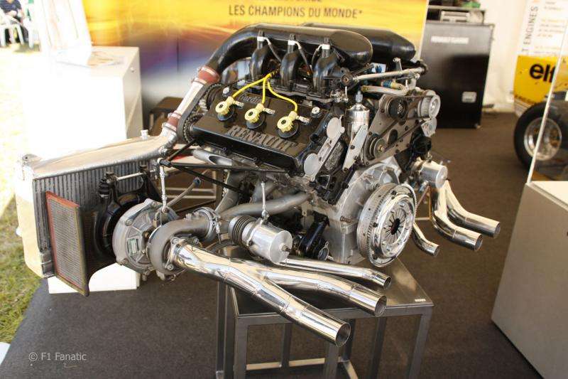
1984 Renault EF4 1.5-litre V6

1984 Renault EF4 1.5-litre V6: Amedee Gordini joined forces with Renault and established new facilities for car and race preparation at Viry-Chatillon south of Paris called Usine Amadee Gordini. Renault’s Gordini works accepted a new challenge in 1972 with the design from scratch of a 2-litre V6 to power a competitor in sports-car racing to be built by a sister Renault company, Alpine, at Dieppe. Alpine’s activities were strongly supported by ELF, the French national oil company, which subsidized the creation of the new engine. The choice of a V6 configuration and a 90 degree vee angle provided a publicity link to a new engine of the same layout that Renault was introducing for passenger cars.
Francois Castaing directed the racing engine’s design and would have much to do with its subsequent evolution. No sooner had the resulting V6 been introduced than Gordini began turbocharging it. Scanting an attractive idea, Elf backed the building of 2-prototypes of a blown 1.5-litre version that could compete in F1 against the naturally aspirated 3-litre engines. The first such Renault Gordini V6, dubbed EF1 in honor of the Elf contribution, ran in July 1977. In 1977 a Renault turbo F1 engine raced for the first time and a victory was first scored in 1979. In 1983 Renault and Alain Prost were vice-champions, in both the driver and manufacturers categories, using the EF3 version of the V6.
For 1984 Renault laid down a new version of the V6 which had the double-oversquare cylinder dimension of 86 x 42.8mm for 1492cc. The EF4 would be raced by Renault’s own team (Warwick – Tambay) and also by 2-other team’s, Lotus and Elio de Angelis – Mansell, and Ligier with De Cesaris – Hasnault. An aluminum cylinder block had been introduced the previous year for the EF3 to replace the V6 original thin-wall cast-iron block. Instead of being made outside by Messier, however, the 1984 block was cast in-house by Renault and incorporated design changes that increased its strength. These were needed in order to cope with the advances being made by turbocharging which year on year was increasing F1 horsepower by huge handfuls.
Critical on highly-boosted engine was the joint between the block and the detachable heads. The block/head attachment was both by conventional studs and by downward-facing short studs to nuts along the periphery of each head. A composite metal gasket provided the Renault’s gas seal while Viton rubber seals took care of oil and water passages. The wet cylinder liners of nitrided steel were clamped into the block by a recessed collar at their very top. At the bottom end of each liner 2 O-rings provided a water-retaining seal against the bore in the block.
Divided at the crankshaft centerline, the bottom end of the EF4 was simplicity itself. The caps for the 4-plain Glyco main bearings were integrated into the sump casting, also of aluminum, bolted to the bottom of the block. This sump casting carried the lower mounts for the engine, which was a stressed member of the chassis.
The 58mm main bearings carried a steel crankshaft machined from a solid billet. It had only 3-48mm throws spaced at 120 degrees each carrying 2-con-rods big-ends. Substantial counter-weights extended from the crank webs opposite each throw and all bearing surfaces were nitrided. Instead of the usual I-section the shank of the nitride steel con-rods were H-section, because they place less mass at the periphery of the rod. The big-ends of the 123mm rods were 2-bolt.
Gerotor-type pumps mounted externally at the sides of the sump powered the lubrication system. Provided were a pressure pump, main scavenged pumps and a smaller scavenge pumps, for the 2-turbochargers, in all, the scavenging capacity was 10-times that of the pressure pump. Driven from the back of each row of pumps was a centrifugal water pump which delivered directly to a manifold cast into the lower level of the side of the block. Water was drawn off from the front of the inlet side of each cylinder head.
The 2-pump arrays were driven by the same system of cogged rubber belts that drove the EF4’s camshafts – an impressive validation of this drive medium for an engine running up to 11000rpm. A disadvantage was the longitudinal space that the belts occupied at the front of the engine, and an important advantage was their light weight compered to gears or even chains.
A small gearcase above the crank nose contained 2-speed-reduced spur gears, each of which drove a sprocket for 1-bank’s belt. 1-spur gear was driven by the crank nose and the other was driven by its neighbor, by this means the 2-belts were made to counter-rotate so that they could be laid out symmetrically. From a wrapping idler the inner tension side was the shortest. Pulling the belt around the large cam sprockets. Another idler ensured a tight wrap around the exhaust cam sprocket. The pump gangs were driven by the bottom of the slack runs of the belts.
The aluminum cylinder heads castings were particularly deep. This served several objectives. It accommodated the very-long-stemmed valves that were needed to allow the inlet ports to run as straight as possible to the valve heads. Stem length was further increased by the decision to place the cup-type tappets above rather than around the valve springs. The tall head also provided room for water passages around the exhaust-valve guides, whose cooling is critical in a turbocharged engine. To this same end the valve stems were hollow and filled with heat-conducting sodium salts.
Atop each head was a shallow aluminum casting which carried the cup-type tappets and the 4 lower Glyco bearing inserts for each steel camshaft. The bearing caps were incorporated in the wide 1-piece camshaft cover. Twin coil springs supplied by Schmitthelm closed each valve. Valve stem inclinations were very slight, 10 degrees for the 29.08mm inlets and 11-1/2 degrees for the 26.1mm exhausts. This facilitated a chamber with a very shallow pent-roof shape that stimulated turbulence of fresh gasses. A single spark-plug was at the centre of the chamber.
The shallow chamber allowed the top of the forged Mahle piston to be flat except for slight indentations for the valve clearance. 3-rings were carried, 2-compression and 1-oil control. The piston of the EF4 was given a higher crown than its predecessor, raising the compression ratio half-a-point to 7.5:1 to help improve fuel consumption for 1984, in which only 220 litres were allowed for the race distance. Achieving adequate ring and piston life in the turbocharged engine was a major challenge for Renault engineers. An oil jet initially provided to cool the underside of the piston crown evolved into a Mahle design that incorporated an internal cooling-oil gallery.
Below a carbon-fibre inlet plenum and ram-tuned magnesium downpipes, each inlet port was fed ELF’s racing petrol blend by a nozzle supplied by a mechanical Kugelfischer injection system. The plunger-type pump was in the engine’s central vee and was driven by a cogged belt from the rear of the right-hand inlet camshaft. Control of its fuel metering cam was by an aerospace servomotor reacting to a Renault-developed electronic micro-processor which responded to 5-engine parameters. A separate processor, triggered by a pickup in the bellhousing controlled the timing of the Marelli Raceplex capacitive-discharge ignition system.
Each bank of the V6 was equipped with its own turbocharging system, using turbo units made by Garrett AiResearch to Renault’s specifications. They had specially-developed turbine wheels and compressor impellers machined from solid billets of aluminum alloy. Boost pressure was controlled by a valve in each 3-branched exhaust manifold – a wastegate – that vented exhaust to the atmosphere when the desired boost was reached. In races boost of up to 32 psi was used, with more readily available for qualifying.
Butterflies at the forward-facing inlets to the turbochargers provided throttle control, upstream from a Renault-developed device, the ‘Dispositive Prerotation Variable’ or DPV. This inserted vanes into the incoming air which could be varied in incidence, either to provide a pre-swirl or to close so that the impeller would be in a semi-vacuum that would help maintain its speed. Turbo output was delivered through an air-to-air intercooler alongside the front of the V6 and was then ducted to the bank’s inlet plenum, within which water was injected – in proportion to boost pressure – further to cool the incoming air.
Complete with starter, clutch and turbo’s, this was a 155kg package that was capable of producing between 660 and 750bhp@11000rpm depending on boost pressure. Its torque peak, reached at 8500rpm, was 354 lb/ft. The EF4’s most successful 1984 user was team Lotus, whose drivers put the 95T on pole twice and were on the podium 6-times. The V6 took Elio de Angelis and Lotus-Renault to 3rd in the 2-respective world championships.

Specifications:

Cylinders V6.
Bore 86mm.
Stroke 42.8mm.
Stroke/bore ratio 0.50:1.
Capacity 1492cc.
Compression ratio 7.5:1.
Con-rod length 123mm.
Rod/crank radius ratio 5.7:1.
Main bearing journal 58mm.
Rod journal 48mm.
Inlet valve 29.8mm.
Exhaust valve 26.1mm.
Inlet pressure 3.2Atm.
Engine weight 155kg.
Peak power 700bhp@11000rpm.
Piston speed corrected 21.9m/s.
Peak torque 480Nm@8500rpm.
Peak bmep 588psi.
Engine bhp per litre 469.2bhp/litre.
Engine weight per bhp 0.22kg/bhp.
Rivals, not enemies.

User avatar
hollus
Moderator
Joined: 29 Mar 2009, 01:21
Location: Copenhagen, Denmark

Re: Specifications of 50 famous racing engines up to 1994

Post

More links on the 1984 Renault EF4 1.5-litre V6:

Image

Image

Image

Image

Image

Image
Rivals, not enemies.

User avatar
hollus
Moderator
Joined: 29 Mar 2009, 01:21
Location: Copenhagen, Denmark

Re: Specifications of 50 famous racing engines up to 1994

Post

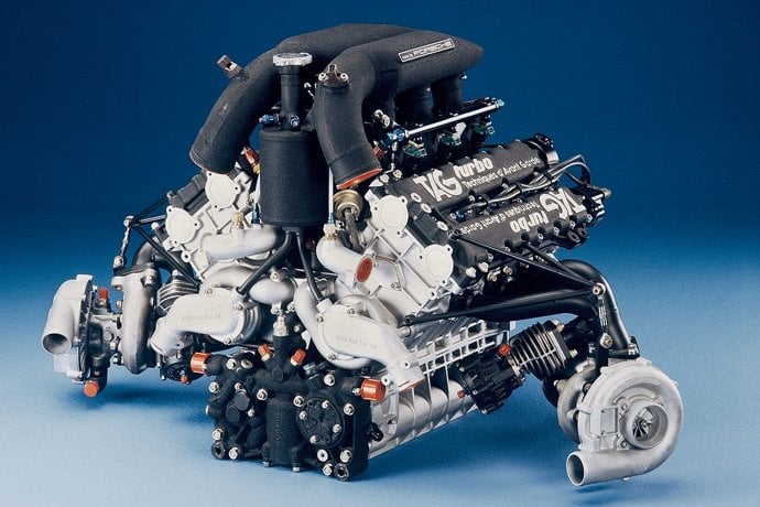
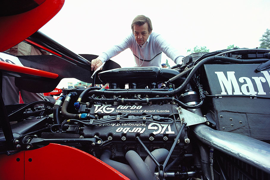
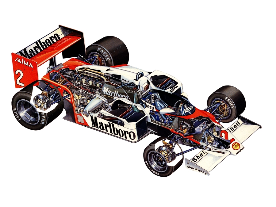
1987 TAG – PO1 1.5-litre V6

1987 TAG – PO1 1.5-litre V6: Porsche renowned for its racing engine expertise. Since its work as consultants to Auto Union and Cisitalia, however, Porsche had been designing and building engines on its own account. Key to its successful work in this field since the 1960’s was the expertise of Hans Mezger, who made major contributions to the type 753 of 1962 and the type 912 engine used in the 1969 type 917. Mazger’s talents were given a new challenge in the 1980’s when Porsche was asked by a customer to design a Grand Prix engine. With first Renault (1977) and then Ferrari (1980) demonstrating the advantage of 1.5-litre turbocharged engines for formula 1 racing, the McLaren team realized that it would have to leave the naturally-aspirated ranks and look for a turbo of its own.
Since October 1980 McLaren – originally established by driver Bruce Mclaren in the 1960 – had been virtually a new company, McLaren International, under the direction of part-owner Ron Dennis, a fellow director was engineer John Bernard. When turbocharging was considered Porsche had to come into the frame, not least because the Stuttgart company had pioneered in the Can-Am series and endurance racing. After the first contact was made by McLaren on 26 August 1981, Porsche carried out a 4-month initial feasibility study for a new Formula 1 engine. Completed in May 1982, this was followed by a full contract, which was financed by a Saudi Arabian company managed by McLaren´s ally Mansour Ojjeh, Technique d’Avant-Garde or TAG.
The resulting engine was thus identified as a TAG unit and given the designation TAG-PO1. Its cylinder dimensions were established as 82 x 47.3mm for 1499cc. First run on the test bench on 18 December 1982, the engine was ready to compete in 4-GP’s in the autumn of 1983 in a provisional McLaren chassis – outings that were declared as tests, not serious entries. In its first full season, 1984, Porsche-designed unit took Niki Lauda to the drivers world championship ahead of Alain Prost in a sister car. It was Prost’s turn to win the championship in 1985, and he did so again in 1986. he had to settle for 4th in 1987, the last season in which the TAG-engine was used. From 1984 to 87 the McLaren-TAG's won more races than any other team.
The engine that made this possible was by no means a cost-no-object exercise. It was built by Porsche to TAG’s strict budged and specification. As well, it was planned by Porsche to fit snugly within a central underfloor channel at the rear of a new car which was planned to generate record high levels of downforce. Before this could be built, however, the racing authorities introduced new rules requiring GP cars to have flat-bottoms. Thus some of the engine’s features, such as high-placed exhaust pipes and a narrow crankcase, became redundant.
A V6 configuration was chosen in preference to the more costly and complex V8 alternative. Hans Mezger set its banks at an 80 degree included angle, narrow enough to allow room under its sides for the (planned) venturi tunnels yet wide enough to accommodate the central induction piping. His analysis of the first – and second – order vibration forces that the engine would generate showed that an 80 degree vee was a good compromise between the two. The angle also suited the expressed requirement for the engine to mount in the chassis as a stressed member, using the same attachment points as the Ford-Cosworth V8.
The PO1’s cylinder block was compact, its deeply-ribbed casting extended down only to the crankshaft centerline and up to the detachable cylinder heads. They and the rest of the engine’s major housings were cast of aluminum alloy by Honsel Werke AG. Inserted into the block were wet cylinder liners of aluminum, their bores coated with Nicasil, a Mahle-developed hard-wearing plated surface of nickel carrying silicon carbide particles. Long-time Porsche partner Mahle also supplied the aluminum pistons, which had an internal gallery through which oil flowed to cool the crown and ring lands. Lightly concave to provide a compression ratio initially of 7.5:1, the piston crown had cut-outs for TDC valve-head clearance. For the 1987 season compression was upped to 8.0:1. 2 compression rings and 1 oil ring were carried above the gudgeon pin. connecting rods were made of titanium, both pistons and rods were made more robust for final 1987 season.
The large bore allowed the 4-valves to be inclined to the left and right at modest angles. Inlet inclination was 14 degrees from vertical and exhaust angle was 15 degrees. In addition the valves were angled slightly in the fore and aft direction to give the chamber a slightly spherical surface and to improve the gas flow in the chamber. To permit this, the tappets were similarly angled and the cam lobes were given a conical profile. (A note here, it should be noted that this was 1987 well ahead of the 3l V10 era when such cam grinds started to be used). Diameters of the Glyco-made valves were 30.5mm inlets and 27.5mm exhausts.
Hollow stems in the Nimonic-steel valves contained salts that accelerated their internal transfer of heat away from the head to the stem and thence to the valve-guide. Extraction of heat from the exhaust-valve seat was significantly improved by tiny drillings that allowed water to circulate through the metal around the seats. A system patented by Porsche, this had its own pipework taking 10% of the water-pump output.
2-coaxial coil springs closed the valves, which were opened by inverted-cup-type tappets. Twin camshafts in each aluminum head were driven by a train of gears from the crank nose. Turned by an idler above the crank nose, the first half-speed spur gear for each cylinder bank also drove a water pump mounted on the face of the PO1’s front cover. Both rotating clockwise, the pumps delivered coolant to the centre of the vee to a manifold cast into the cylinder block, and to the previously-mounted exhaust-seat cooling system. Water flowed back along the cylinder liners, up past the exhaust valves and out through passages on the inlet side of the head. Magnesium was used for the pipes to the water pumps and from the heads.
Also mounted on the front cover were the scavenge and pressure oil pumps. These were placed at the front instead of in the increasingly-popular side-mounted location, as pioneered by Cosworth’s Ford V8, in order to meet the objective of a narrow crankcase that would offer minimum obstruction to an underbody venturi. Tunnels along the sides of the sump casting collected oil flung from the crankshaft and fed it to the scavenge pumps, the pressure oil feed to the crankshaft was through the nose of the crank, as had been Porsche´s racing practice since the type 753 flat 8.
Made by Alfig Keesler, the nitride-steel crankshaft had the straightforward layout of 4-main bearings and 3-rod throws – with side-by-side rods – that was pioneered for the racing V6 engine by Carlo Chiti’s 1961 120 degree vee Ferrari. Fully counterbalanced, it was carried in Clyco thin-wall lead-bronze bearings, as also used for the rod big-ends.
Although with the 80 degree Vee angle this did not provide equally-spaced firing impulses, the uneven timing could easily be accommodated by the Bosch Motronic engine management system. At Bosch Dr Udo Zucker headed the team that progressively developed the TAG engine’s control system. By 1985 all the control elements were combined in a single package, which - at a time when fuel consumption was critical - could tell the driver how many laps he could complete with his reserve of fuel at the boost pressure he was running. The final Bosch MP1.7 system used 2-solenoid-controlled valves, aiming at 30 degrees down into each inlet port, to inject fuel volumes that varied according to a highly detailed map of engine speed plus such factors as humidity, altitude, torque and engine deceleration or acceleration. Throttle control was by individual butterflies above the injection nozzles.
Long-time Porsche partner KKK supplied the engine’s twin turbochargers. Frustratingly for perfectionist engineer John Bernard, KKK took a year and a half to produce mirror-image units that allowed him to improve exhaust-gas flow to the right-hand turbocharger. Porsche’s own wastegates, finned for cooling, provided boost pressure control in the exhaust manifolds just upstream of the turbine entries. The turbo-compressors delivered through air-cooled intercoolers to individual plenum chambers feeding each cylinder bank.
The policy of Mclaren and Porsche was to run essentially the same engine in qualifying and the race. Three different turbines and two compressor types were available for the HHB model KKK turbochargers, these could be mixed and matched to tailor the set-up to the circuit, with the larger turbine giving more power but at a sacrifice in throttle response. Typical power in racing trim was 820bhp@12000rpm with a boost of 36psi. Maximum torque was 390 lb/ft@8800rpm. With a higher qualifying boost of 41 psi the V6’s horsepower exceeded 900.
The engines ran on a special toluene-based petrol developed by Shell. High reliability helped Porsche fulfill its TAG contract with remarkably few engines, only 15 were used in the first full season and a mere 50 or so for the entire program. In relation to the resources expended the project was a resounding success.

Specifications:

Cylinders V6.
Bore 82mm.
Stroke 47.3mm.
Stroke/bore ratio 0.58:1.
Capacity 1499cc.
Compression ratio 8:1.
Con-rod length 115mm.
Rod/crank radius ratio 4.9:1.
Main bearing journal 48mm.
Rod journal 45mm.
Inlet valve 30.5mm.
Exhaust valve 27.5mm.
Inlet pressure 3.48 Atm.
Engine weight 150kg.
Peak power 860bhp@12000rpm.
Piston speed corrected 24.5m/s.
Peak torque 529 Nm@8800rpm.
Peak bmep 645 psi.
Engine bhp/litre 573.7 bhp/litre.
Engine weight per bhp 0.17kg/bhp.
Rivals, not enemies.

User avatar
hollus
Moderator
Joined: 29 Mar 2009, 01:21
Location: Copenhagen, Denmark

Re: Specifications of 50 famous racing engines up to 1994

Post

Some more on the 1987 TAG – PO1 1.5-litre V6:

https://www.enginelabs.com/features/dev ... f1-engine/

Image

Image

Image

Image

Image

Image

Sound:
Rivals, not enemies.

saviour stivala
saviour stivala
52
Joined: 25 Apr 2018, 12:54

Re: Specifications of 50 famous racing engines up to 1994

Post

Fantastic picture/photo of cylinder block.

User avatar
hollus
Moderator
Joined: 29 Mar 2009, 01:21
Location: Copenhagen, Denmark

Re: Specifications of 50 famous racing engines up to 1994

Post

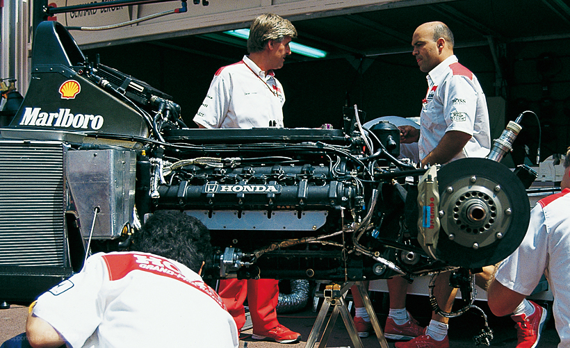
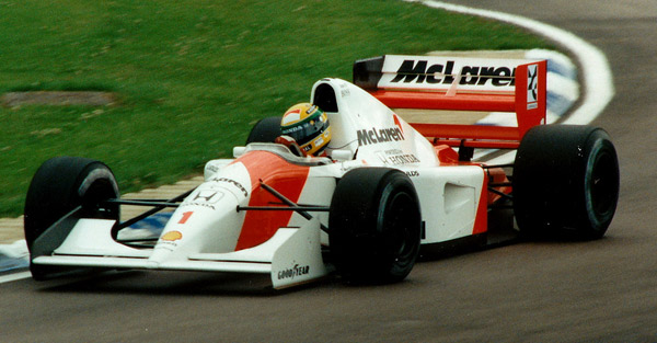
1992 Honda RA122E/B 3.5-litre V12

1992 Honda RA122E/B 3.5-litre V12: When Honda returned to formula 1 racing in 1983 it did so with clear objective of achieving an international reputation as one of the ‘noble’ automotive brands al-la Mercedes-Benz, Alfa Romeo and Ferrari. Much like Renault, Honda launched this new initiative by turbocharging a V6 that had previously been used in formula 2 racing, in partnership with Williams, it won the constructors championship in 1986 and 1987, adding a driver’s trophy for Nelson Piquet in the later year. The last year for Honda turbo was 1988, when McLaren moved from the TAG engine to become a Honda team. This saw another constructors championship with 15 wins in 16 races and a season-long battle between Prost and Senna for the driver’s championship.
With turbos banned, after such a spectacularly successful year Honda gave serious consideration to withdrawing from F1, Soichiro Honda counselled continuation, pointing out that a new level playing field had just been created on which Honda could confirm its superiority. Accordingly it began the new 3.5-litre Formula 1 of 1989 with a V10 engine and a continuation of its McLaren partnership, which was to last until 1992. The V10 was raced in 1989 and 90, bringing 2-more constructors cups and driver championships for Prost and Senna. To meet the intensifying completion from Ferrari and Renault a 60 degree V12 was introduced in 1991, under development since 1989, this RA121E brought Mclaren-Honda both championships again.
However, the pace of progress was such that Honda elected to build an all-new V12, The RA122E/B, for 1992. Begun in July 1991, work on it was delayed by the concentration late that season on the improvements of its predecessor to meet the demands of both McLaren and Senna. The new engine's vee angle was widened to 75 degrees to lower its height and centre of gravity and to make more room in the vee to package the fuel pump and alternator. Compared to the previous 12's cylinder dimension of 86.5 X 49.6mm the new unit was more oversquare at 88 X 47.9 mm for 3496cc to suit the then-current 3.5-litre Formula 1.
High silicon aluminum alloy was used for both the block and the heads, the block terminated at the crankshaft centerline. Bolted to its bottom surface was a large casting of Electron WE54 magnesium alloy which incorporated the caps for the 7-main bearings, the sump and the mountings for the accessory-drive gears across the front of the sump, driven from the crank nose. Each of the 6-individual sump chambers, housing a crank throw with its 2-connecting rods, had a close-fitting circular cross-section. A slot along its lower right-hand side was fitted with guides to collect oil thrown from the crank and channel it to the scavenging pumps. For the first time, Honda placed all the Gerotor-type scavenge pumps on the right side of the engine’s sump: 4-large pumps to exhaust the crankcase, 2-small ones for the cam cases and a single small pump for the gear case for the drive to the camshafts, which was at the rear of the V12. The pump capacity was high enough to reduce the pressure in the crankcase to 30 percent of atmospheric. Which – compared to 64 percent of atmospheric - increased engine power by 2-percent at 14000rpm.
On the left side of the engine the gear train drove the water pump and the pressure oil pump. All pumps were positioned as far forward as possible to allow the downpipes from the tuned exhaust manifolds to be tucked closely to the crankcase. This in turn improved the packaging of the adjacent cooling radiators and their ducting. Cast-in galleries for both oil and water ran down the engine’s central valley. Included in the cooling system were jets to the underside of the pistons that reduced the temperature of the ring lands by 10-20 degrees C.
Short fully-skirted pistons carried 2-compression rings and 1-oil ring in a configuration optimized to reduce blow-by. Although pent-roofed, their crowns had marked indentations that exactly matched the slightly tuliped contours of the 4-valve heads. By this close attention to detail Honda was able to give the RA122E/B the high compression ratio of 12.9:1 in spite of its very large cylinder bore.
The cam lobe forms were tailored asymmetrically to reduce the need for valve-head clearance near TDC. Surrounding the pistons were aluminum wet liners with a Nicasil running surface, clamped by a top flange into the block. 2-o-rings in grooves in the liner completed the bottom end. Circlips retained the gudgeon pins in the pistons. The bushing at the small end of the 111mm con-rod received oil through a drilling at its top. Made of titanium, the rods had a robust ‘I’-section and a massive 2-bolt big-ends. Each 40mm rod journal was doubly counter-weighted in a crankshaft configuration that resulted from tests by Honda of many prototype designs. Drillings in the steel crank checks adjacent to the journals helped lighten the throws to reduce the balance mass requirements.
Trains of spur gears up the rear of the block drove the V12’s 4-overhead camshafts. Having relatively large 30mm base circles, the cams were hollowed for lightness. They were carried in plain bearings which were between the valve pairs, although many designers of high-speed engines were now putting the bearings between the valves in each pair to minimize any chance of unwanted cam flexing.
Inverted-cup-type tappets were used. Honda’s analysis of coil valve springs showed that if a spring force of 107kg were needed to avoid valve bounce at 13000rpm, a force half again as great would be needed at 15000rpm and twice as large at 15700rpm. This led it to adopt pneumatic valve closing, for the RA122E/B. Weighing half as much as coil springs and their retainers, the pneumatic system reduced the valve reciprocating weight by 20 per-cent. Honda chose nitrogen as the system’s working gas, the McLaren carrying a reserve supply at 150 atmospheres in 2-small cylinders mounted on the firewall. Gas was metered at 6 to 8 atmospheres to the volume under each tappet. The space was sealed by an inverted tulip-shaped titanium cup, called a ‘piston’ by Honda. It was sealed to the valve stem and had a ring seal at its bottom, sliding in the tappet bore. Careful tweaking of the system allowed an 800rpm speed increase before the onset of valve bounce, even with the unusual cam profile adopted to keep the valves away from the pistons at TDC.
Complete with the required gas passages, bulky tappet-carrying blocks were bolted into each cylinder head. Gas seals were also provided for the inserted valve guides. Extra cooling for the exhaust-valve guides was provided by exposing a short portion of it directly to the coolant. Mutually inclined at an included angle of 28 degrees, the 36.5mm inlet valves were made of titanium alloy and the 28.5mm exhaust valves of nickel alloy. The latter were made hollow for lightness, and sealed at the head.
A feature Honda had introduced during 1991, variable-length inlet ram pipes, was engineered from the start into the new V12. A hydraulic actuator for each bank of pipes moved the top funnels over a 25mm range. From 8000 to 15000rpm an electronic controller operated solenoid valve to rise and lower the funnels 3-times to help fill in troughs in the power curve. Below the funnels were the butterfly-type throttle valves, and bellow them were 2-nozzles for the electronically-controlled sequential fuel-injection system. The drivers had no direct control over the Honda’s throttles. Each row of 6-butterflies was operated by a 4-phase electric stepping motor which was able to position the throttles within 0.1 degree and move them from closed to open in an 8th of a second. Inputs to the electronic control included engine speed and gear selected as well as throttle position, which dramatically reduced incidents of engine overspeeding – thus making another contribution to reduced valve-to-crown clearance and a high compression ratio.
Reliability of the new and complex systems was not 100 per-cent: the failure of a stepping motor cost Senna victory in the Canadian GP, which Berger won. Nor was the high-revving Honda a paragon of fuel economy. McLarens had to start some of the faster races with more than 220 litres of fuel compared to 185 for cars with Cosworth V8 power. A 27kg weight handicap, but the V12’s output by the end of the season of 774bhp@14400rpm offered considerable compensation, as did its torque of 297 lb/ft@12000rpm.
Although its new MP4/7A chassis was not one of McLaren’s best efforts, Senna won at Monte Carlo, Hungary and Monza and Berger added season-ending Australia to his Canadian win. The 2-drivers were 4th and 5th in the world championship in Honda’s penultimate official season in formula 1 in the 20th century, for after 1992 it decided to withdraw - until 2000.

Specifications:

Cylinders V12.
Bore 88mm.
Stroke 47.9mm.
Stroke/bore ratio 0.54:1.
Capacity 3496cc.
Compression ratio 12.9:1.
Con-rod length 111mm.
Rod/crank radius ratio 4.6:1.
Main bearing journal 54mm.
Rod journal 40mm.
Inlet valve 36.5mm.
Exhaust valve 28.5mm.
Inlet pressure 1 Atm.
Engine weight 154kg.
Peak power 774bhp@14000rpm.
Piston speed corrected 29.8m/s.
Peak torque 403 Nm@12000rpm.
Peak bmep 210psi.
Engine bhp per litre 221.4bhp/litre.
Engine weight per bhp 0.20kg/bhp.
Rivals, not enemies.

User avatar
hollus
Moderator
Joined: 29 Mar 2009, 01:21
Location: Copenhagen, Denmark

Re: Specifications of 50 famous racing engines up to 1994

Post

A few extra links on the 1992 Honda RA122E/B 3.5-litre V12:
Image
Image

Image

Image

Image

Plus some stuff, together with a lot other random stuff, hidden here:
http://www.grandprixengines.co.uk/Significant_Other.pdf
Rivals, not enemies.

User avatar
hollus
Moderator
Joined: 29 Mar 2009, 01:21
Location: Copenhagen, Denmark

Re: Specifications of 50 famous racing engines up to 1994

Post

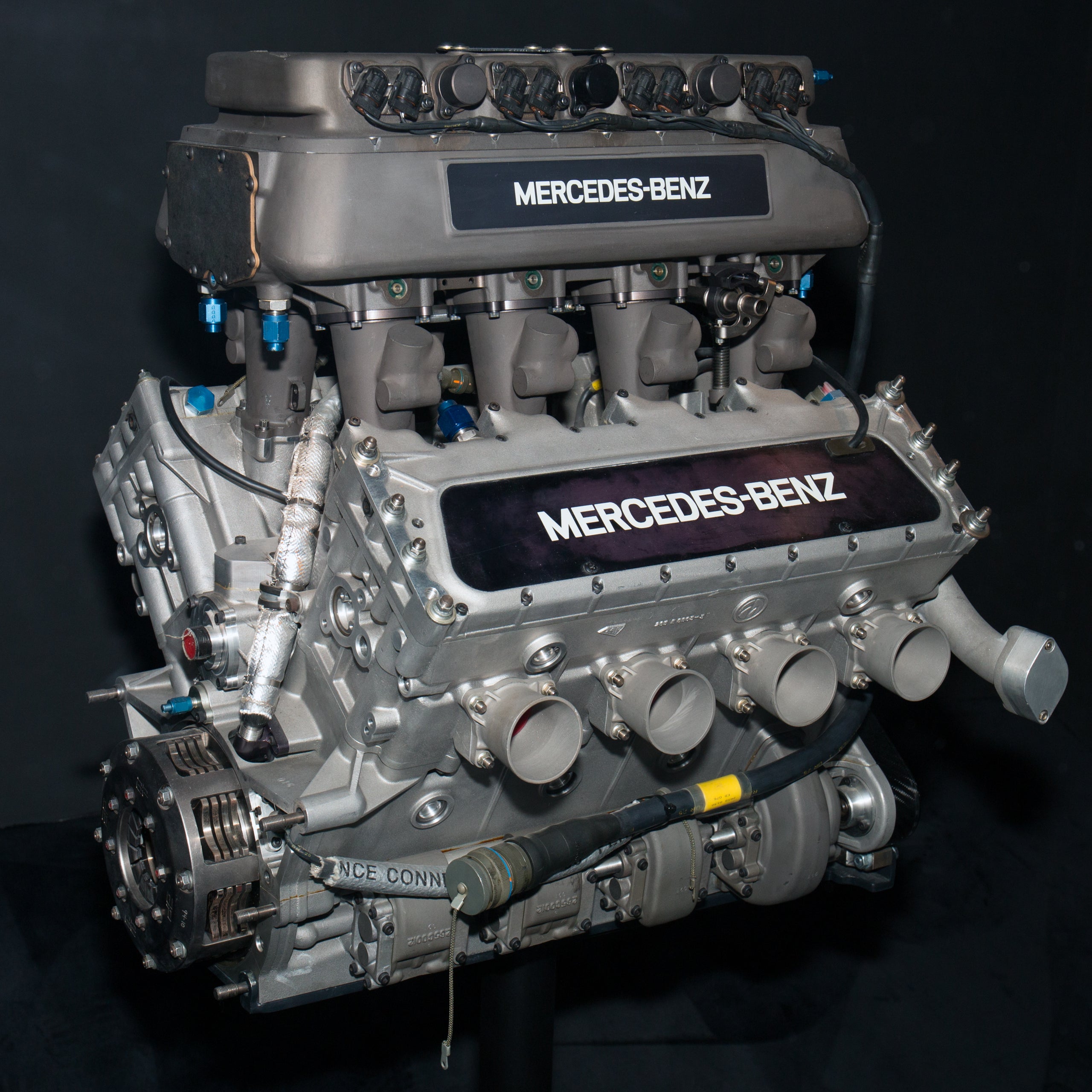
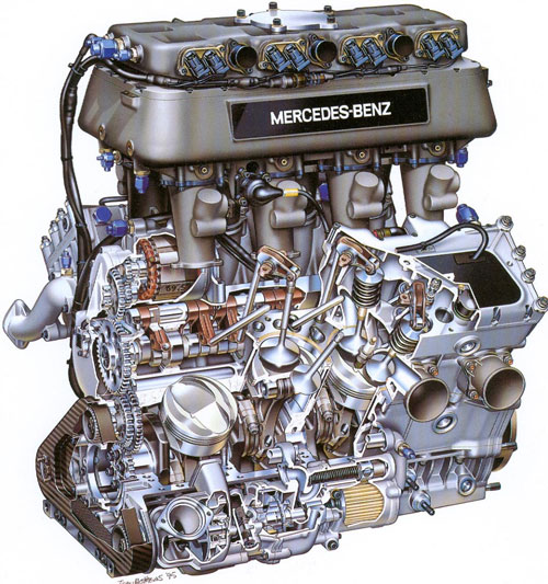
1994 Mercedes-Benz 5001 3.4-litre V8

1994 Mercedes-Benz 5001 3.4-litre V8: Indianapolis rules of 1994 left a loophole big enough to drive a Mercedes-Benz through, and that’s what happened. To fill-up the field, turbocharged engines using production cylinder blocks were allowed a displacement of 3.430cc in no more than 8-cylinders, 29.4% more than the 2.65-litres that pure racing engines were permitted. Such engines also had to have non-overhead single camshaft and 2-valves per cylinder operated by pushrods. For Indy they could be supercharged at 12-1/2 psi, which was 22% higher than the 2.65-litre engine were allowed. These advantages were not convincing when such engines were built using stock blocks, but when the rules were changed to allow special blocks to be made some people smelt an opportunity, among them were Mario Illien and Paul Morgan of Ilmor engineering, of Northamptonshire, makers of racing engines for Chevrolet and latterly Mercedes-Benz .
Mercedes and Ilmor part-owner Roger Penske approved a plan to build a unique engine to these rules for the 1994 race. Bottom-end elements of the Mercedes 5001, as it was named, resembled those of Ilmor’s 4-cam 2.65-litres Indy V8 with the exception that the gear drive to the single camshaft was at the front instead of at the rear. 5-plain main bearings were carried in bulkheads in the aluminum block and capped at the bottom by a single aluminum casting also forming the dray sump. Together they were stressed and structured to serve as an integral part of the car’s frame.
Within the matching block and sump castings each rod journal rotated in a circular cavity shaped to generate as little drag as possible. Oil was drawn out of each cavity through a slot at its bottom right, each cavity having its own scavenge pump mounted outside the sump on the right side. These pumps used Roots-type rotors which have high capacity for their size and also a high tolerance of any aeration of the oil.
On the left of the sump was a single water pump, it fed the left side of the block directly and then through the housing of the forwardmost scavenge pump, behind the water pump in the same alignment were a centrifuge to fling air out of the oil, a pressure oil pump and an oil filter. All these pumps were carried over from Ilmor’s 4-cam Indy V8, although with a stepped-up ratio for the toothed rubber belt that drove them. A gear on the crank nose drove a compound spur-gear train to the single central camshaft. A take-off from an intermediate gear drove a tooted belt to the oil and water pumps.
At the nose of the camshaft, planned as an integral part of the concept, was a pendulum-type vibration damper. The rear end of the camshaft drove the scavenge pump for the turbocharger, which was mounted astern of the engine. Within cylinder centres of 109mm, a bore diameter of 97mm was accommodated. The stroke of 58mm provided a capacity of 3429cc. a scant 0.9cc less than the legal limit. Cylinder banks were set at 72 degrees vee angle.
The wet cylinder liners were steel, topped by a flange that was grooved to take a solid sealing ring. The cylinder head clamped the ring and liner flange against the closed-top deck of the block, the liner’s bottom end floated in the block and was sealed with O-rings.
Each head was attached by 10-main studs extending deeply into the block. rows of 4-cup screws along each side faced downwards in the central vee and upwards beneath the exhaust ports with their 4-attachment studs. Short skirted slipper-type pistons were forged of aluminum by a contractor using Ilmor’s dies and then finish-machined by Ilmor. Each piston carried 2-compression rings and 1-oil control ring. The periphery of the piston crown was very precisely machined to give a ‘squish’ effect to the mixture during the compression stroke. Compression ratio was 11:1. As mandated by the Indy rules, the gudgeon pin and connecting rod were made of steel.
The con-rods with their 2-bolt big-end, was forged and had an ‘I’-section shank. It measured 116mm from centre to centre. A 180 degree flat-plane crankshaft, with 4-large counterweights, was machined from a solid steel billet. To increase its mass the periphery of each counterweight was drilled and tapped to accept a row of screwed-in tungsten-alloy plugs of high specific weight.
The 5001’s valve layout could be likened to an inclined-2-valve chamber rotated by 20 degrees in plan view, from the conventional transverse–valve position. In their plane, the inlet valves were inclined at 10 degrees and the exhaust valves at 13 degrees. A single 12mm Bosch spark-plug was also positioned at compound angles and sloped towered the exhaust-port side of the head. The heads of the titanium valves differed sharply in size: 52.5mm for the inlets and 39.7mm for the exhausts. Valve-seat inserts in the aluminum head were used, those for the exhaust valves having a higher proportion of copper in the alloy for improved heat transfer. The valves were closed by dual coil springs with titanium retainers.
Opening them was a unique pushrod valve gear arrangement. Instead of the cylindrical tappets that were used in almost every other known pushrod engine (automotive and aviation) Ilmor selected a pivoted finger-type follower with a roller in contact with the cam lobe. Down the centre of the engine vee ran a shaft from which all the finger followers hinged downwards. A dedicated oil supply to and along this shaft provided lubrication for the followers pivots and to the rollers and cam lobes as well. From each follower a stainless-steel pushrod went up to its rocker arm. Each rocker pivoted on its own dedicated shaft, which was attached by 2-studs to the flat surface of the head. The rocker arm was roller-tipped where it contacted the cap atop the valve stem. Between the follower and the rocker arm a lift multiplication ratio of 2.175:1 was provided from the cam-lobe. Valve lift was a generous 15.7mm for the inlets, 14.4mm for the exhausts.
The 5001 cam profile gave the following timing: Inlet opens 87 degrees BTDC. Inlet closes 87 degrees ABDC. Exhaust opens 84 degrees BBDC. Exhaust closes 84 degrees ATDC. Every rotating element of this entire valve train ran on anti-friction bearings. The camshaft turned in 4-caged roller bearings on 45mm journals and, at the front, a ball bearing to retain it in place. Every other bearing in the valve gear consisted of needle, crowded without cages. Each of the finger followers pivoted on 2-rows of needles. The follower rollers, the rocker-arm pivots and the rocker-arm roller tips – all turned on needle bearings.
Atop the engine was an aluminum plenum chamber with internal ram pipes, patterned after the successful design used on Ilmor’s smaller Indy V8. Electronic injection nozzles mounted in the top of the plenum chamber sprayed fuel straight down into each inlet ram-pipe. Delco electronic ignition fired the spark-plugs. In the plenum 2-Rochester fuel injectors for each cylinder, 16 in all, were under the control of a Delco electronic engine management system.
Exhaust manifolding from both cylinder banks was united at the rear of the engine and fed into the exhaust scroll of its single Garrett AiResearch TA74 turbocharger. The turbocharger’s dimensions were strictly controlled by the USAC rules, which made no distinction in this respect between overhead-cam and push-rod engines. An exhaust waste-gate responding to boost pressure regulated the turbocharger’s compressed air output. Its response was tailored to bring the engine to the maximum allowable boost pressure at 4000-to-4500rpm and then to hold it level, to generate a flat torque curve. Adjustments of the boost to suit atmospheric conditions was made by the driver with a rotating wheel that varied the bleed-of boost pressure to the diaphragm controlling the waste-gate.
At only 124kg without turbocharger the 5001 V8 was impressively light. Its peak output was an ‘uncorrected’ 965-to-970bhp@9800rpm. Corrected for temperature and atmospheric conditions the peak power was 1024bhp. Peak torque was 557 lb/ft@8000rpm. The engine could survive at speeds up to 10400rpm but for the ‘500’ a 10000rpm rev limit was set – still a remarkable speed for a pushrod engine.
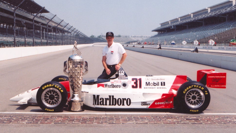
During May’s practice for the 500-mile race, driving a 5001-powered Penske PC94 Emerson Fittipaldi set the fastest lap speed of the month at staggering 230.438mph. The fastest lap by an ‘ordinary’ 2.65-litre car was Michael Andretti’s 227.698mph. In a sister PC94-5001 AL Unser, Jr qualified for the race in the coveted pole position with a 4-lap average of 228.011mph with a last lap at 229.481mph. In the only Penske-Mercedes to reach the finish, Unser assumed the lead on lap 184 and held it to the final flag. He covered the 500 miles in 3-hours and 6-1/2 minutes for a winning average speed of 160.872 mph. Only 7-laps of the race had not been led by the 5001 engine. The victor’s purse was a handsome $1,373,813.

Specifications:

Cylinders V8.
Bore 97mm.
Stroke 58mm.
Stroke/bore ratio 0.60:1.
Capacity 3429cc.
Compression ratio 11:1.
Con-rod length 116mm.
Rod/crank radius ratio 4:1.
Main bearing journal 58mm.
Rod journal 50mm.
Inlet valve 52.5mm.
Exhaust valve 39.7mm.
Inlet opens 87 degrees BTDC.
Inlet closes 87 degrees ABDC.
Exhaust opens 84 degrees BBDC.
Exhaust closes 84 degrees ATDC.
Inlet pressure 1.86 Atm.
Engine weight 132kg.
Peak power 1024bhp@9800rpm.
Piston speed corrected 24.1 m/s.
Peak torque 755 Nm@8000rpm.
Peak bmep 402 psi.
Engine bhp per litre 298.6bhp/litre.
Engine weight per bhp 0.13kg/bhp.
Rivals, not enemies.


User avatar
hollus
Moderator
Joined: 29 Mar 2009, 01:21
Location: Copenhagen, Denmark

Re: Specifications of 50 famous racing engines up to 1994

Post

That's 50, folks.

Thanks for the trip, very specially to Stivala.
Rivals, not enemies.

User avatar
dren
226
Joined: 03 Mar 2010, 14:14

Re: Specifications of 50 famous racing engines up to 1994

Post

That went quick, thanks again for all of the effort. I'll be visiting this thread often!
Honda!

saviour stivala
saviour stivala
52
Joined: 25 Apr 2018, 12:54

Re: Specifications of 50 famous racing engines up to 1994

Post

hollus wrote:
15 May 2019, 19:13
That's 50, folks.

Thanks for the trip, very specially to Stivala.
Thanks hollus. This small but veritable gold mine of technical information wouldn’t have been possible to share with around twenty eight thousand others on here without your help and effort.

stevesingo
stevesingo
42
Joined: 07 Sep 2014, 00:28

Re: Specifications of 50 famous racing engines up to 1994

Post

Thanks for a fascinating read.

This should be made a sticky or some such.