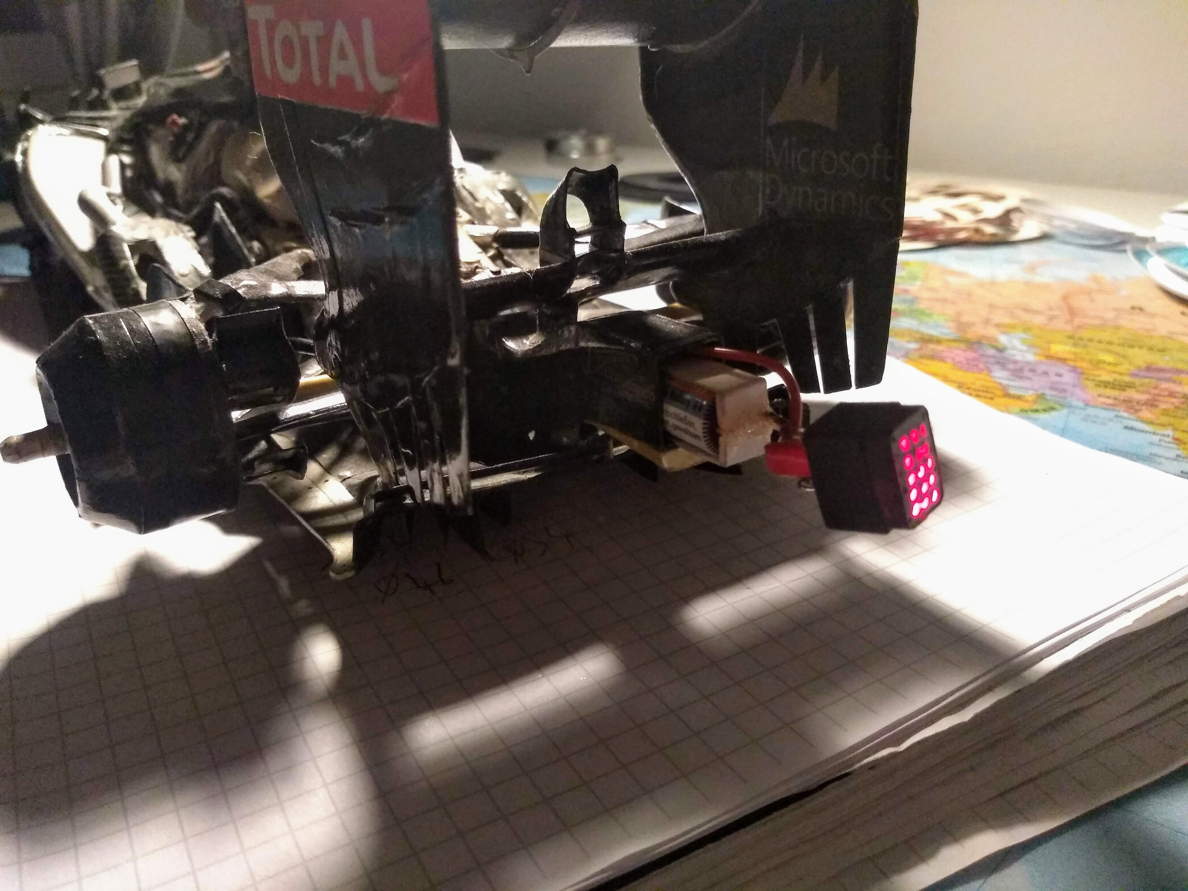
A paperboard Lotus E21

Post here information about your own engineering projects, including but not limited to building your own car or designing a virtual car through CAD.
User avatar
PaulB
72
Joined: 17 Oct 2010, 09:52
Location: Graz/Austria

Re: A paperboard Lotus E21

Post

Hey all,

anybody an idea, what this logo is?

Image
Source: http://f1partsfinder.co.uk/attachments/ ... over_1.jpg

Thanks beforehand
Cheers, Paul
"Being second is to be the first of the ones who lose!" - Ayrton Senna

Paul Bischof
Milton Keynes, UK
MK2 2HL
http://paulsf1.wordpress.com/

R_Redding
R_Redding
54
Joined: 30 Nov 2011, 14:22

Re: A paperboard Lotus E21

Post


User avatar
PaulB
72
Joined: 17 Oct 2010, 09:52
Location: Graz/Austria

Re: A paperboard Lotus E21

Post

Great, many thanks Rob!
"Being second is to be the first of the ones who lose!" - Ayrton Senna

Paul Bischof
Milton Keynes, UK
MK2 2HL
http://paulsf1.wordpress.com/

User avatar
PaulB
72
Joined: 17 Oct 2010, 09:52
Location: Graz/Austria

Re: A paperboard Lotus E21

Post

Engine cover with PDRS, internal areo devices, fitting last barge boards and starting wheel design.

A lot of time passed by since my last post, mainly caused by moving into a new flat. However, I can report some new bits on the car.

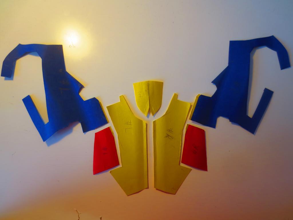
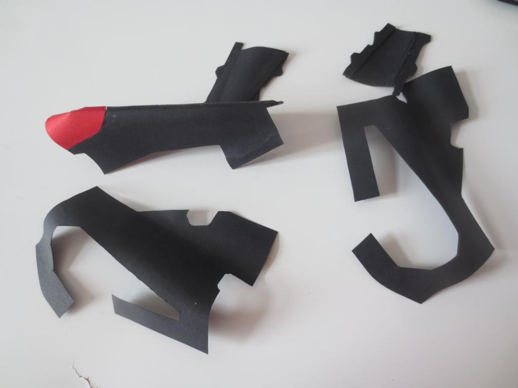
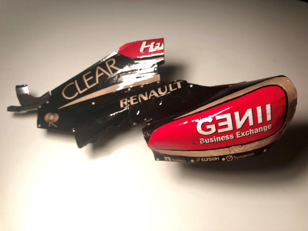
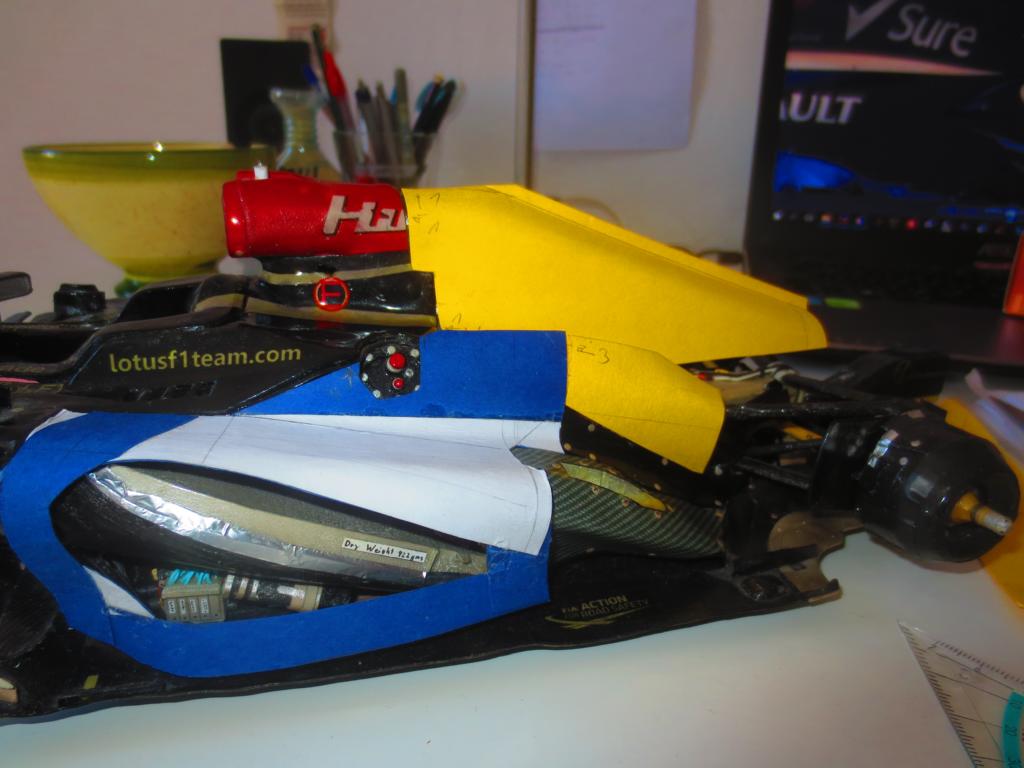
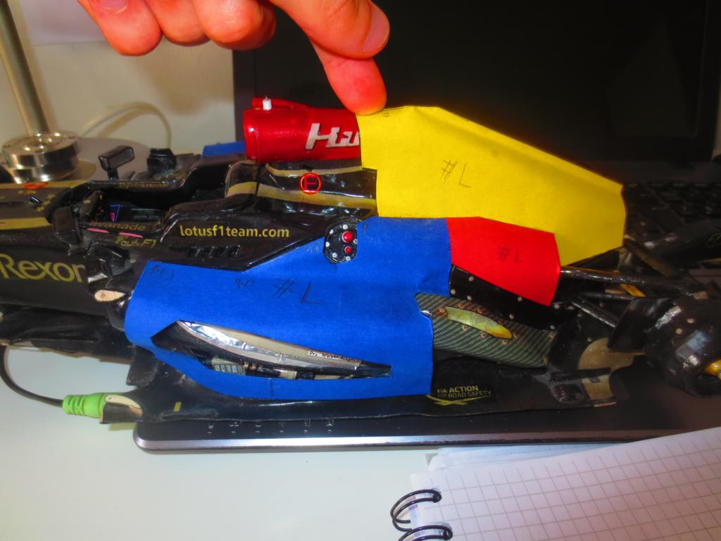
First to the engine cover. Maybe the most tricky part/assembly on the whole car. As mentioned in the previous post, I cannot produce the engine cover exactly to its original dimensions, but I have to adapt it to the bodywork that is already fitted to the car. This is a process, that usually takes a lot of time and several prototypes (up to twelve in case of a Renault R26 ten years ago) are made on my previous cars. On the Lotus I surprised myself in building only two protoype engine covers till I reached the ideal shape. The engine cover consists of five main elements (one cover each side pod/radiators, one over each side of the engine, central piece at the top/airbox) plus the PDRS duct.

PDRS means Passive Drag Reduction System and is actually a passive f-duct system. A few teams (for example Lotus and Mercedes) tried to get them work and actually tested them on track. As this system with its (passive) fluid switch is highly complex and no team was able to get it work properly (as far as I know and remember). Also Lotus aborted the project after FP2 at Belgium GP in 2013. However, due to their limited resources, they used one airbox with its PDRS inlets over the entire season and only closed them, when PDRS was not in use.

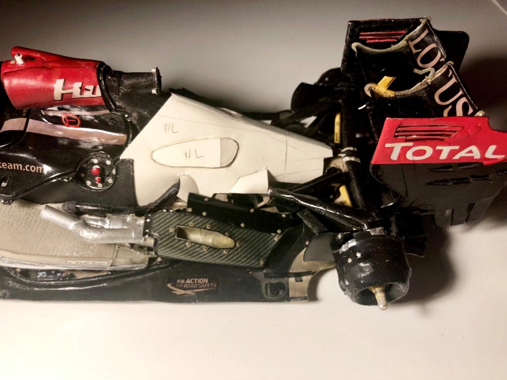
Secondly, the shape of the internal areo covers are finished and only needs to be covered with carbon texture. The intention of the internal areo devices is to reduce the drag of the internal airflow. These internal areo covers appeared first in the 2009/2010 season. They mainly cover the engine and secure a relatively clean surface to minimise the drag for the airflow which exits the radiators.

I also started to fit the last barge boards, which I already produced a few month ago, but did not fit them in order to prevent damage in the course of working on the car. Now, the car is almost finished, and I don't need to work at the car directly any more - so no more danger of damaging them.

The last major project are the wheels. Unfortunately I was not able to find a proper gold paper (the Lotus rims were painted in gold each year). So I have to produce the structure of the rims from white paper and cover it with thin gold paper. Not the perfect way...

Remaining to-do’s are:
  • Finishing rain light
  • Wheel nuts
  • Finishing wheels
  • Cover internal aero with carbon structure
  • Fitting pre-manufactured items (wind screen, top camera, antenna, pitot-tube)
A few pictures from the engine cover production:

First prototype with its different main elements in different colours.
Image

Second and final prototype with its different elements in different colours.
Image

Final prototoype in 2d.
Image

Base elements of the engine cover.
Image

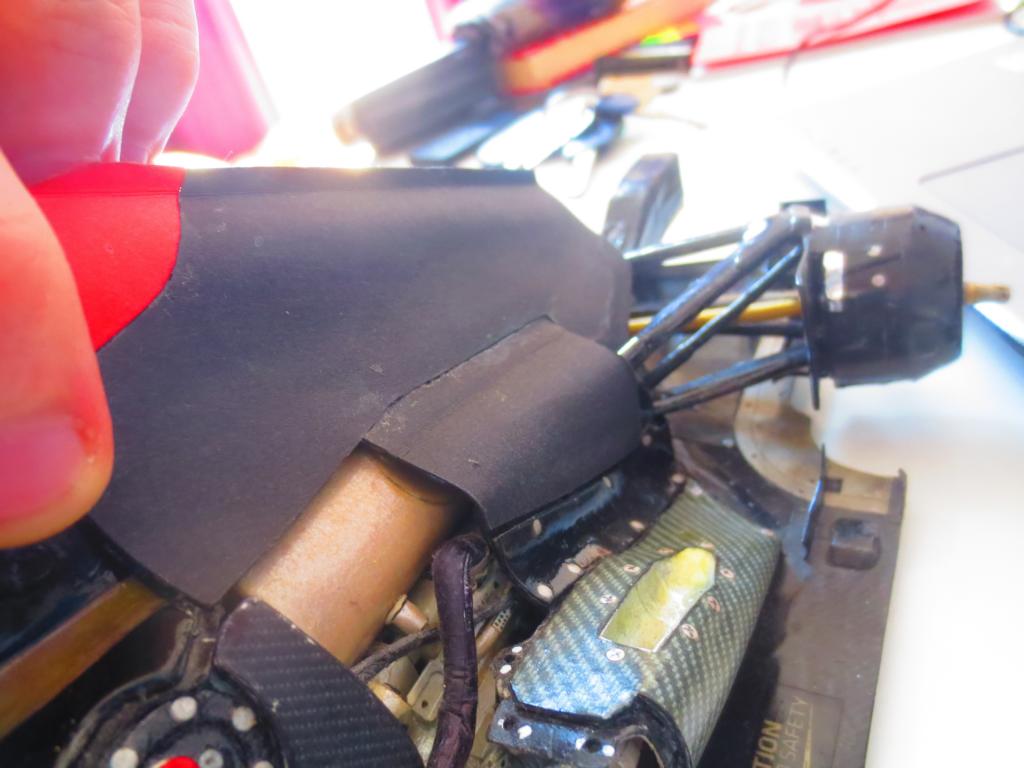
Engine cover on the car for a fitting test - pretty tight packaging.
Image

PDRS pipe inside the engine cover.
Image

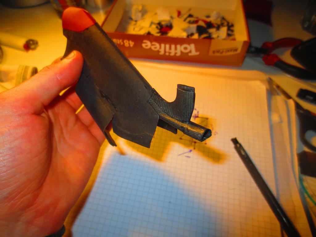
The PDRS pipe exits at the back of the engine cover and points towards the rear wing.
Image

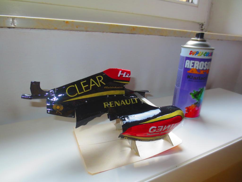
The engine cover on the painting jig.
Image

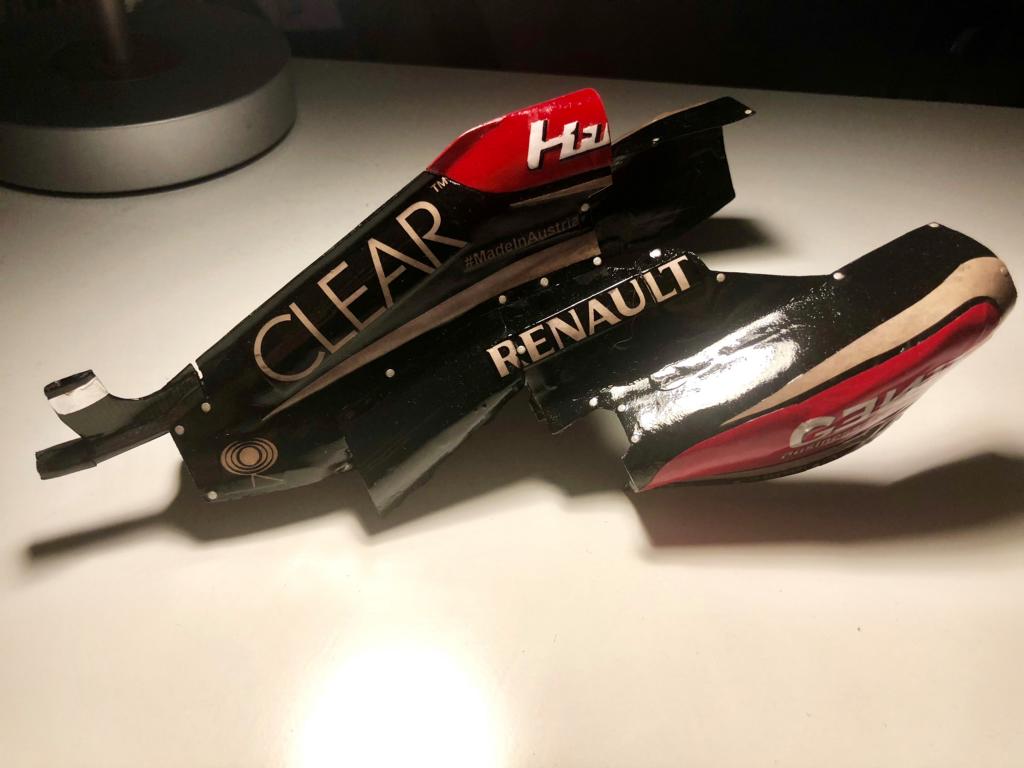
Two more of the finished engine cover.
Image
Image

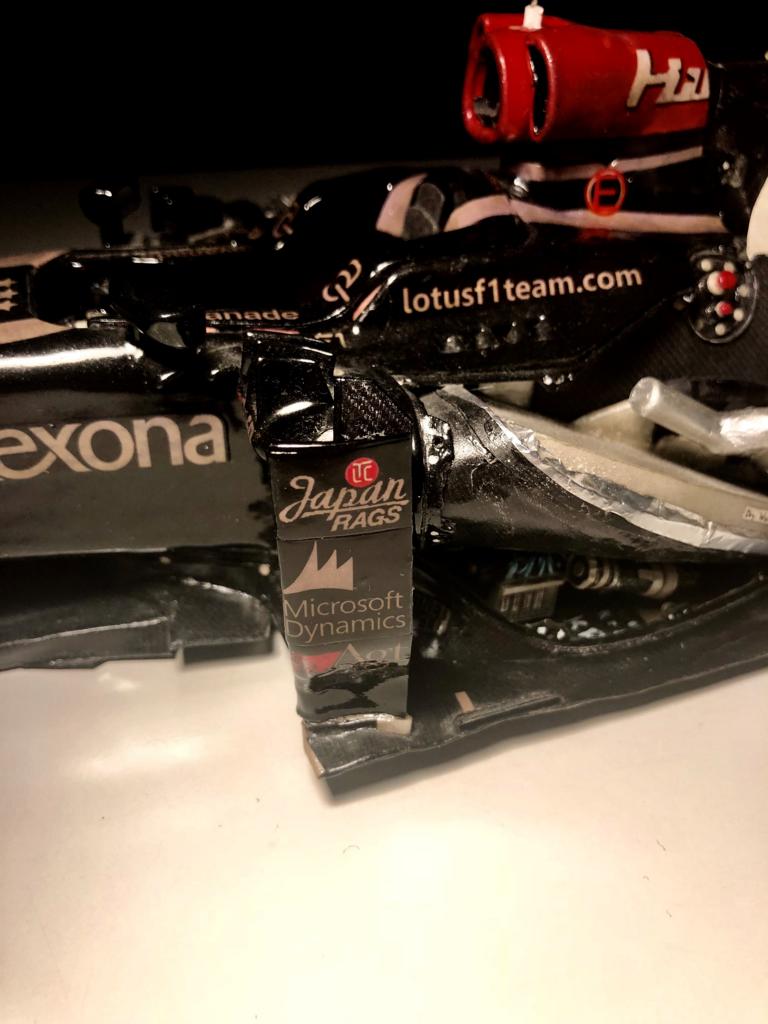
Barge board fitted to the car. The connection strut to the side pod is still missing.
Image

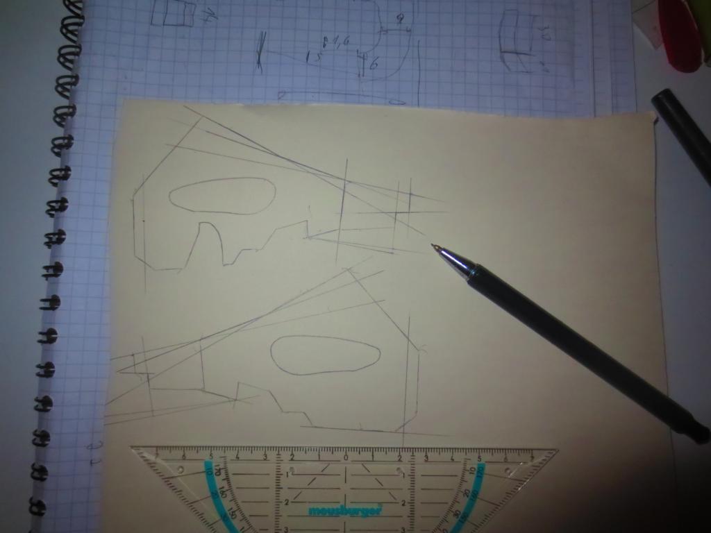
Construction of the internal areo devices.
Image

Internal aero device fitted to the car. Only the carbon texture is missing.
Image

Starting point of the wheels...
Image

That's it for the moment. Thanks for reading. :)

Cheers,
Paul
"Being second is to be the first of the ones who lose!" - Ayrton Senna

Paul Bischof
Milton Keynes, UK
MK2 2HL
http://paulsf1.wordpress.com/

John86045
John86045
0
Joined: 26 Sep 2018, 11:56

Re: A paperboard Lotus E21

Post

thanks

User avatar
PaulB
72
Joined: 17 Oct 2010, 09:52
Location: Graz/Austria

Re: A paperboard Lotus E21

Post

Cheers guys, another uodate on my Lotus:

Wheel design, wheel nuts and a real premiere: the first time I designed a working rear light.

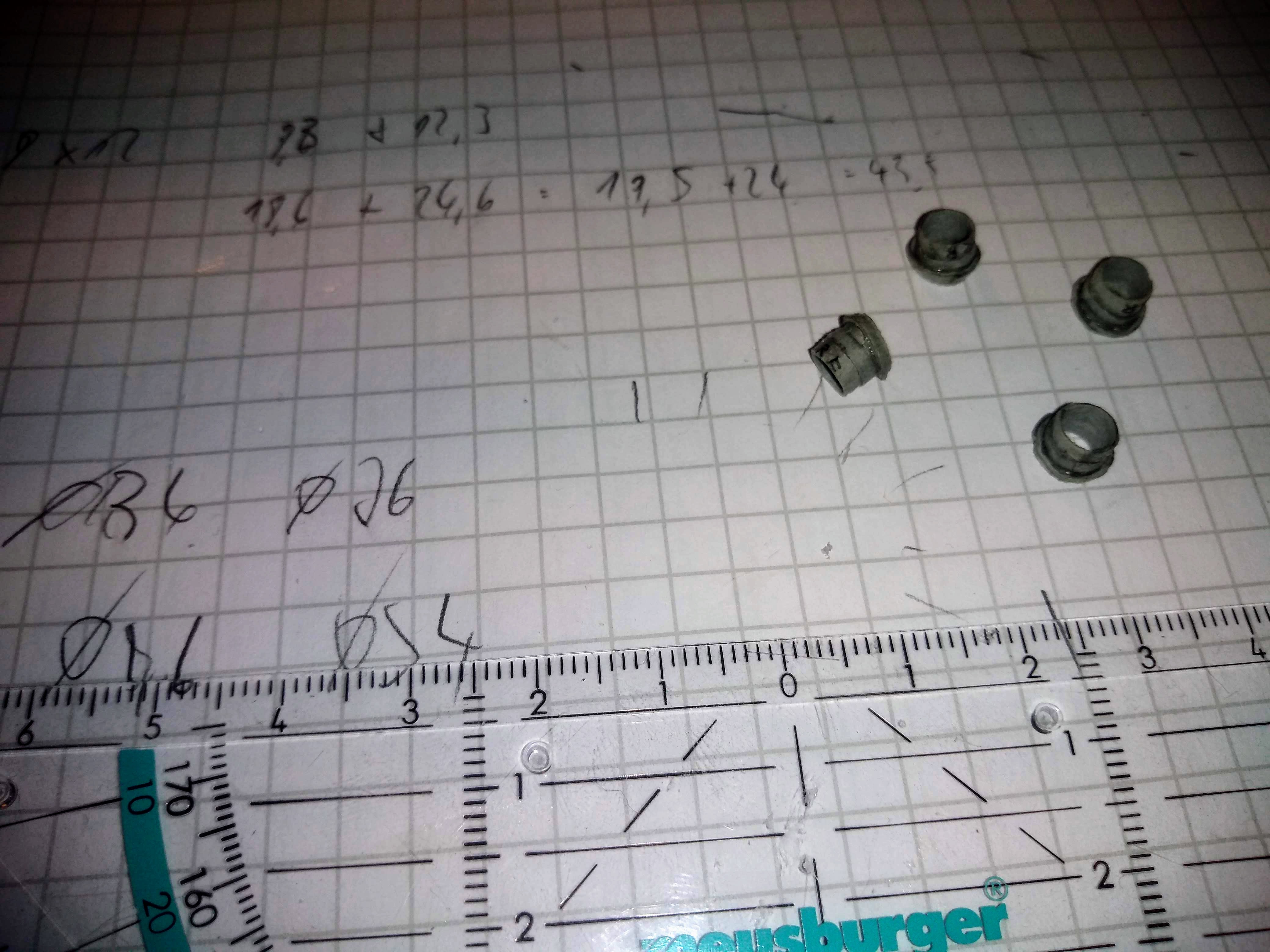
The wheel nuts are a pretty simple. Indeed, I was not able to include the female features for picking up the wheel gun adapter. However, one wheel nut consists out of fife elements. Basically it is only two cylinders and a conical frustum. The wheel hubs are fixed to the rims on order not to lose them during a pit stop (this system was introduced in 2012 I think).
Image

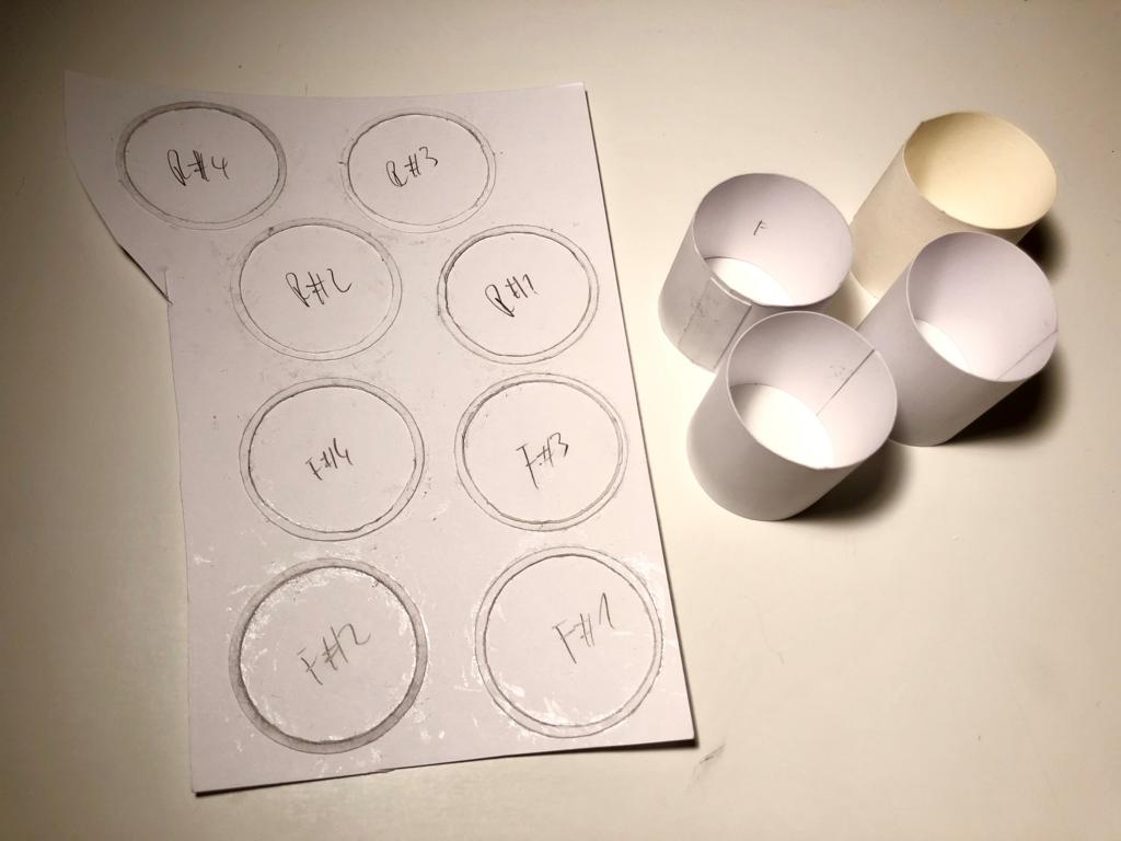
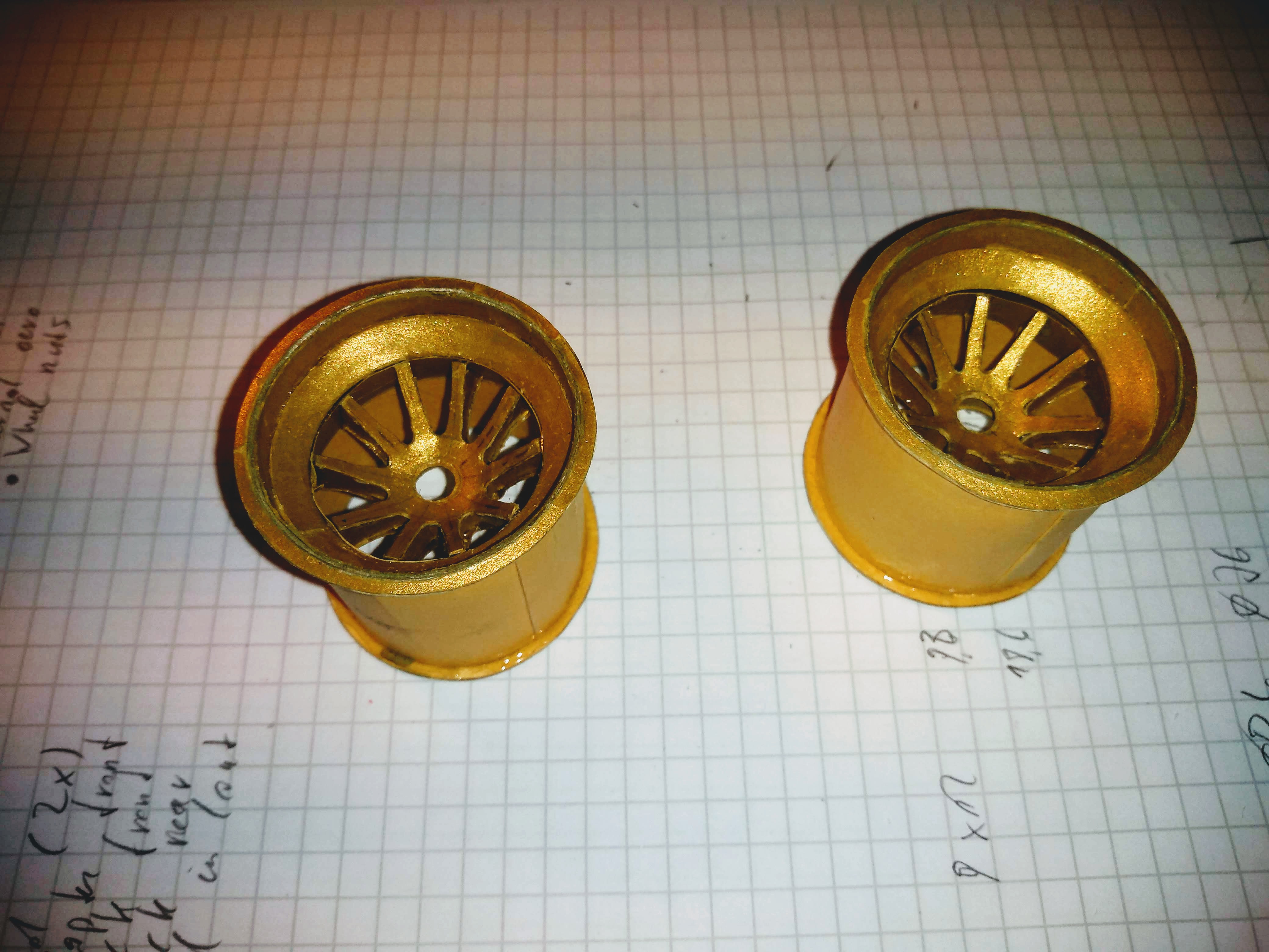
The wheel design was a lit le bit tricky. I needed three approaches to get them done:

1. The first approach (with white paper – because I was not able to find structural cardboard in the correct colour) was designed as medium size wheels. Page 44 of the 2013 FIA Formula One regulations:

12.4 Wheel dimensions:
12.4.1 Complete wheel width must lie between 305mm and 355mm when fitted to the front of the car and between 365mm and 380mm when fitted to the rear.
12.4.2 Complete wheel diameter must not exceed 660mm when fitted with dry-weather tyres or 670mm when fitted with wet weather tyres.


My wheels were designed with 33mm at the front and 37mm at the rear. I made a dimension check with the finished rim cylinder (without spokes). There, I detected, that the rear axle was about 4mm and the front about 3mm too wide (max. 180mm). So this design was dumped in a very early stage.
Image

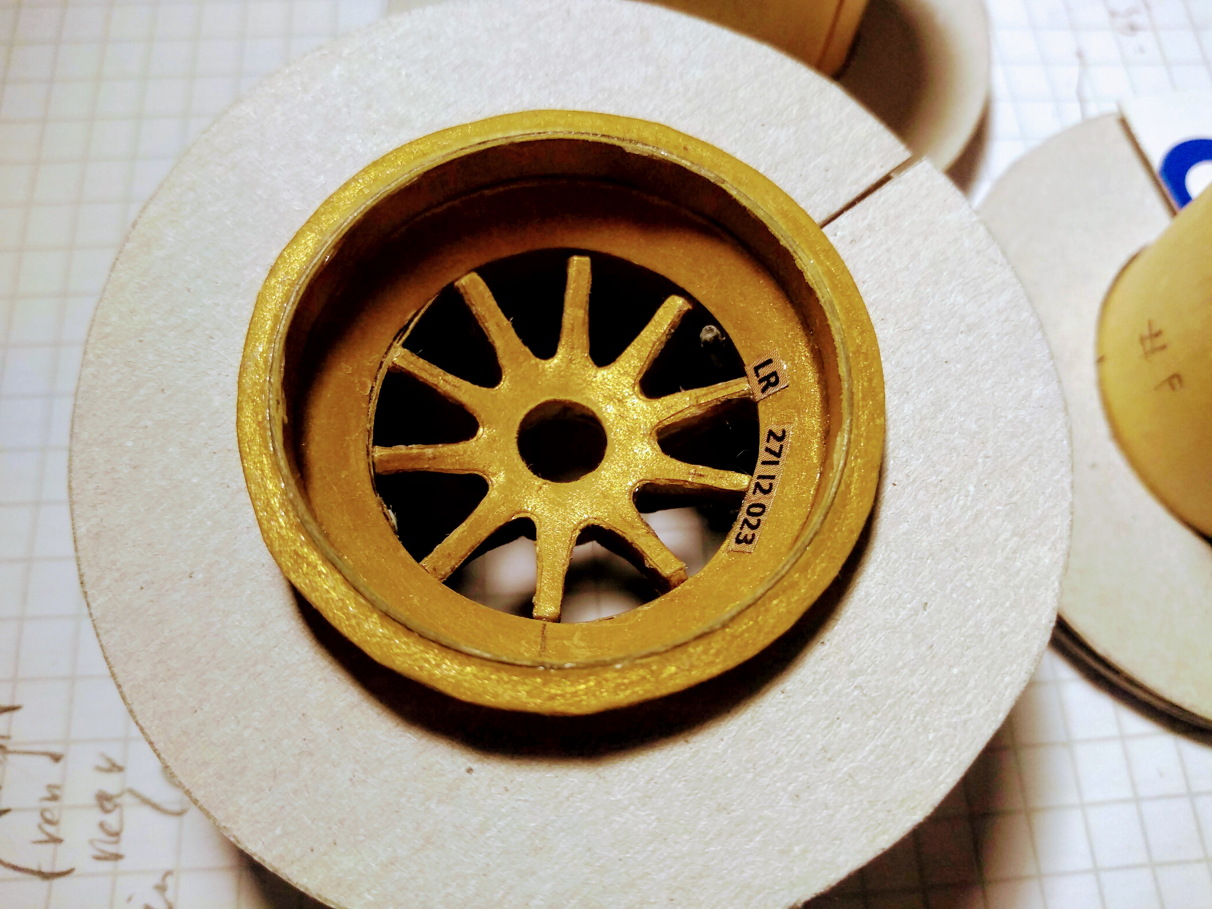
2. For the second approach, I found a cardboard, which has almost the correct colour. However, the rims are covered with a thin paper in the correct colour. In this approach, I designed the wheels to the minimum allowed distance. This time I made it to the complete rim with spokes, followed by another regulation test. To my astonishment, the car was to wide by 9mm at the rear and 7mm at the front.
The reason for this was, that the spokes collided with the brake calipers, so I had to redesign the whole cross section of the rims. One of the largest design faults I've ever done...
Image

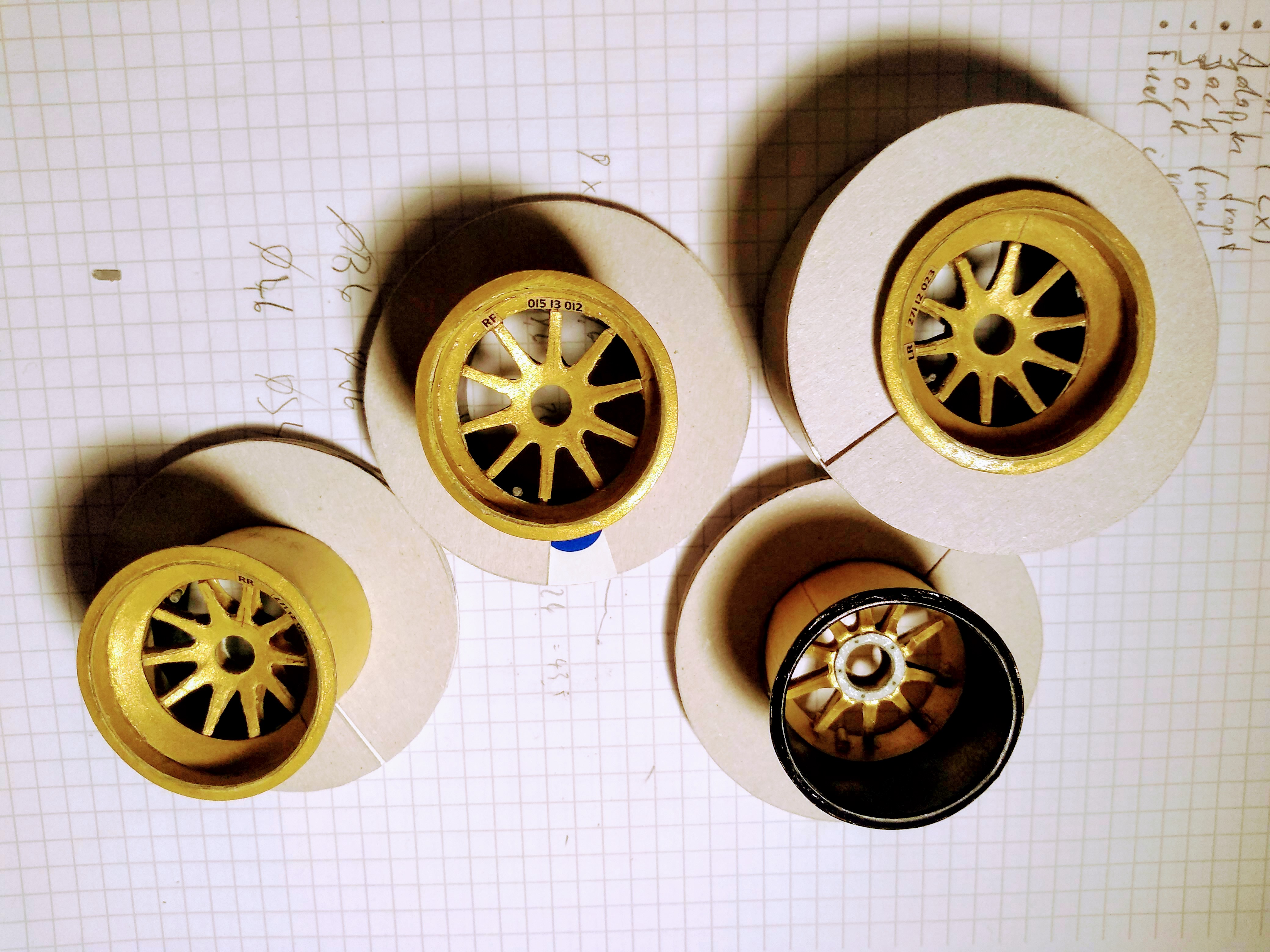
3. For the final approach, I redesigned the whole cross section with highest care and to the minimum dimensions permitted. This approach finally works and the car should be just within the regulations by less than half a mil.
Image
Image

At the moment I am waiting for the OZ logo which my dad is reworking it graphically (the logo is bent around the rim radius and I do not have a powerful photo tool to do this). Most of the tires are also finished and only waiting till the rim is lacquered.

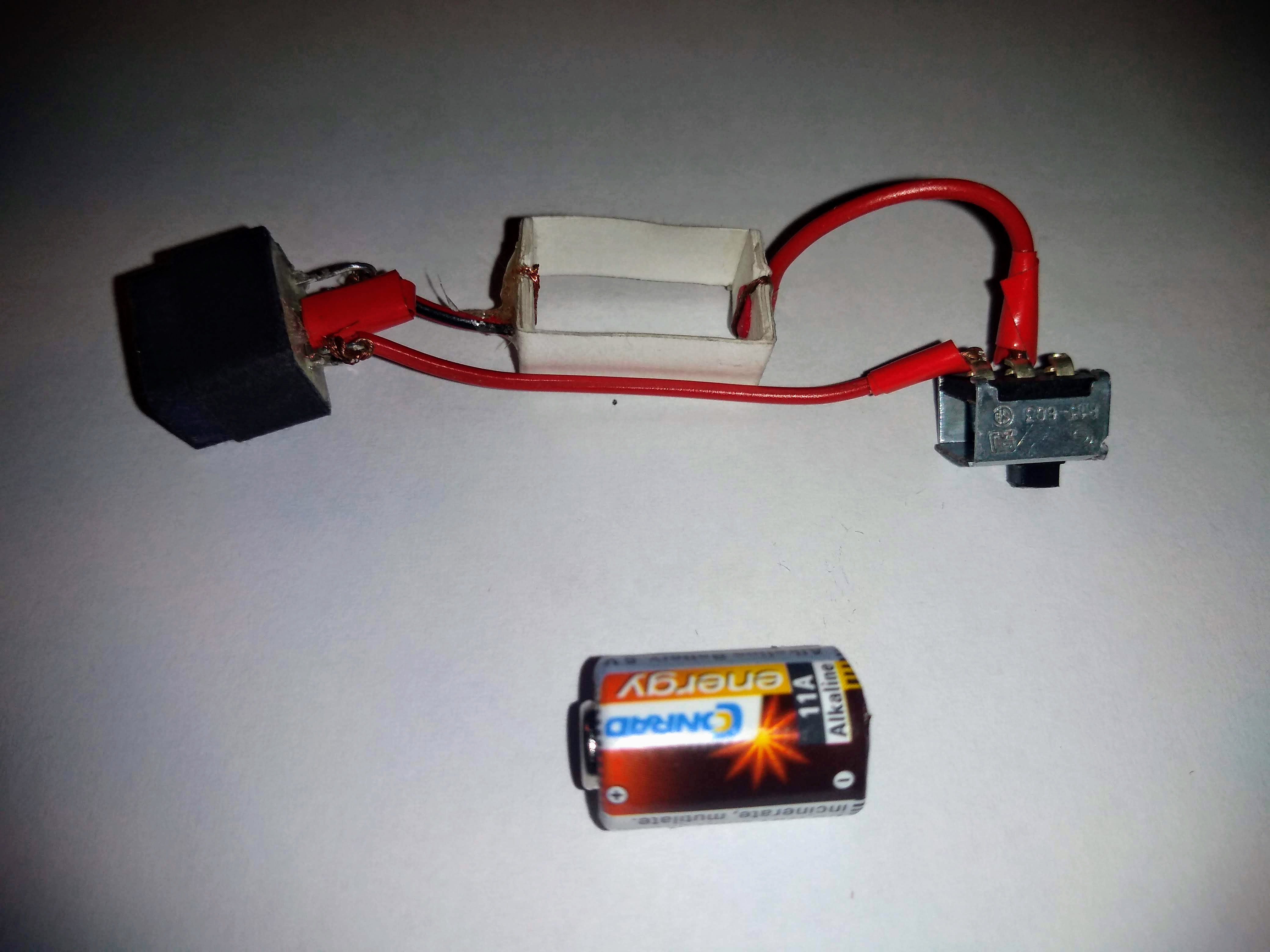
And finally, a premiere: For the very first time, I designed a working rear light. It was a bit of a challenge to find appropriate electronic components. The geometrical boundary conditions are 9.5mm x 11.5mm in cross section (inner dimensions of the rear crash structure). Finally, I found a 6V micro cell battery (for an LED, a minimum voltage of 3V is required) with 10mm in diameter and 16.3mm in length. A sliding switch with 20mm x 14mm x 8.5mm was too large. Even if I removed the unnecessary material, the switch is too large. So my electronics consists only from the battery with a cardboard pick up structure, two LEDs incorporated in the light housing and wiring. It is just enough space to get it fit into the rear crash structure.
Image
Image


"Being second is to be the first of the ones who lose!" - Ayrton Senna

Paul Bischof
Milton Keynes, UK
MK2 2HL
http://paulsf1.wordpress.com/

User avatar
Phil
66
Joined: 25 Sep 2012, 16:22

Re: A paperboard Lotus E21

Post

Amazing! Astonishing! Beyond belief that kind of detail Paul! Thanks for sharing!
Not for nothing, Rosberg's Championship is the only thing that lends credibility to Hamilton's recent success. Otherwise, he'd just be the guy who's had the best car. — bhall II
#Team44 supporter

Cannonballer
Cannonballer
2
Joined: 29 Apr 2015, 03:12

Re: A paperboard Lotus E21

Post

Really an amazing project. I have enjoyed watching your progress over the last years. Please keep us updated.
Wazari wrote: There's a saying in Japan, He might be higher than testicles on a giraffe...........