2 stroke thread (with occasional F1 relevance!)

All that has to do with the power train, gearbox, clutch, fuels and lubricants, etc. Generally the mechanical side of Formula One.
manolis
manolis
107
Joined: 18 Mar 2014, 10:00

Re: 2 stroke thread (with occasional F1 relevance!)

Post

Hello all.

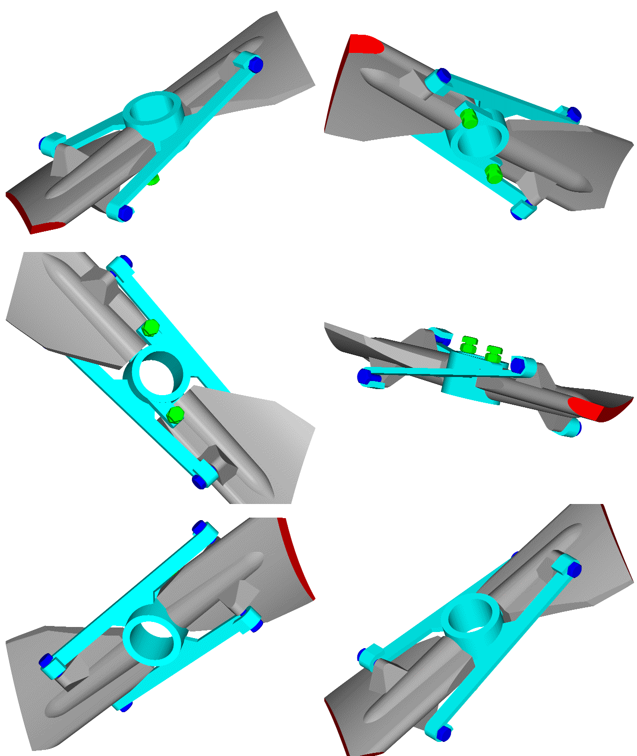
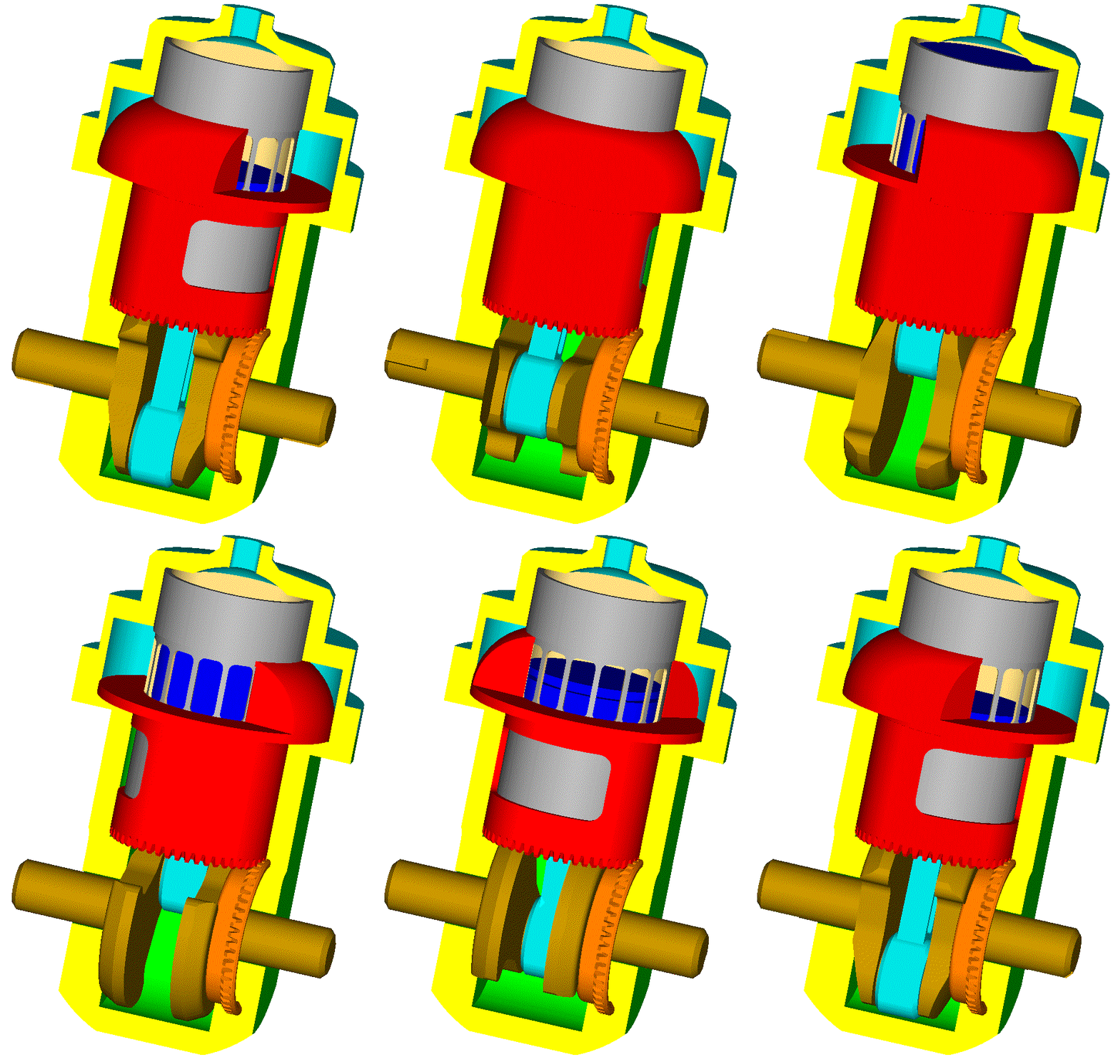
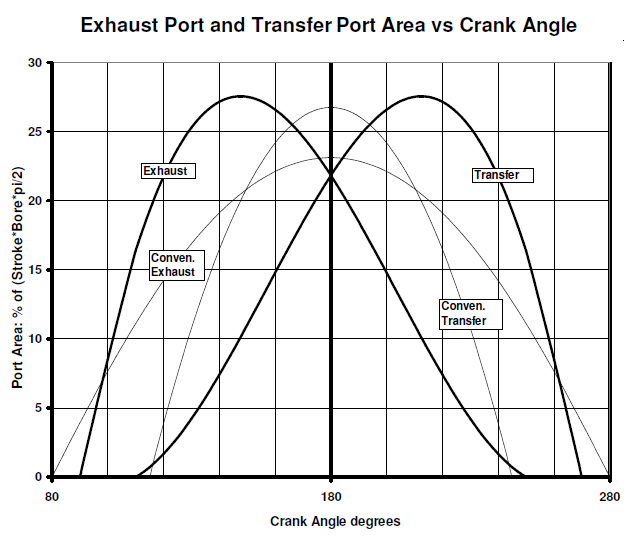
Today it is granted by the UK-IPO (United Kingdom Intellectual Property Office) the patent for the PatATE 2-stroke engine:

Image

Image

Image

More at https://www.pattakon.com/pattakonPatATE.htm


Hello PlatinumZealot.

Neither Zapata, nor Mayman, nor Yves Rossi (all JetMan) need to be strong to control their JetPacks.

Only Browning needs strong arms because he takes a big part of the thrust force by his arms.

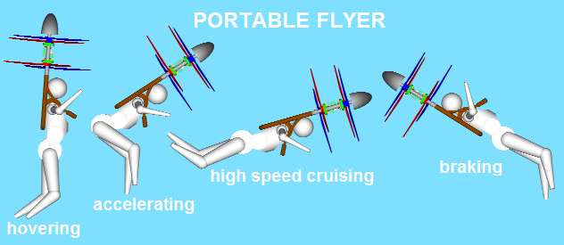
The GEN-H4 has significant limitations as compared to the Portable Flyer.


By the way, this is the no. 3,001 post in this discussion!...

Thanks
Manolis Pattakos

manolis
manolis
107
Joined: 18 Mar 2014, 10:00

Re: 2 stroke thread (with occasional F1 relevance!)

Post

Hello Tommy Cookers.

You write:
"regarding the previously-mentioned automatic adjustment of 'propeller' (or 'proprotor') pitch .....
isn't this what has been the normal way of propellers for 80 years ?
(how/why ?) is something desired beyond this existing range of capabilities ?
(as I said a year ago) today (for 'recreational' aircraft anyway) there's (some anyway) such capability without moving parts by suitably 'tailored' propeller structural properties available from use of composite materials
proper propeller maps seem irritatingly rare ..."


With propellers having 43" diameter / 15" pitch and spinning at 3,500rpm, the total static thrust of the Portable Flyer:
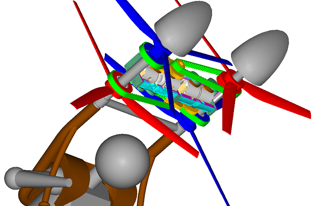
Image

is more than 1000N (100Kg), while the required power by the engine(s) is about 30kW; however even with the propellers spinning at 4,500rpm, the maximum speed is limited at only 100Km/h.

In order the Portable Flyer to be able to cruise at 250Km/h, the required propeller pitch is nearly 40".
With 40" pitch, instead of 15" pitch, the power required by the engine(s) at hovering, take off and landing is overdoubled.

If the propeller pitch could be properly, and widely, adjusted to the operational conditions then, among others, the hovering duration, the top speed and the maximum take-off weight would substantially increase.


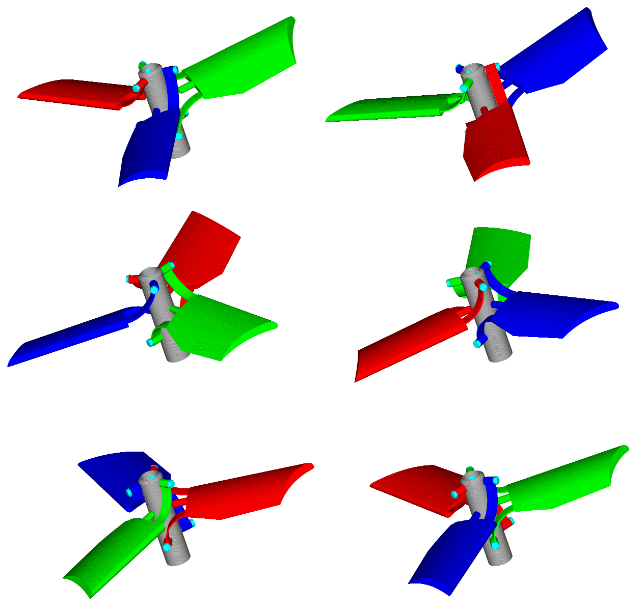
Here is a variable pitch propeller:
Image

(slow motion at https://www.pattakon.com/Pitch/PatPitch_2_slow.gif)

Spot on the blades that move slightly outwards when the propeller spins faster.


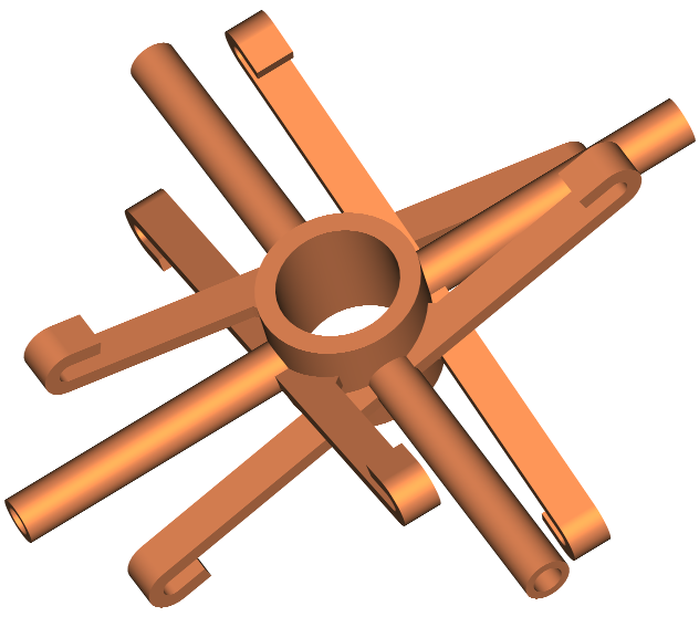
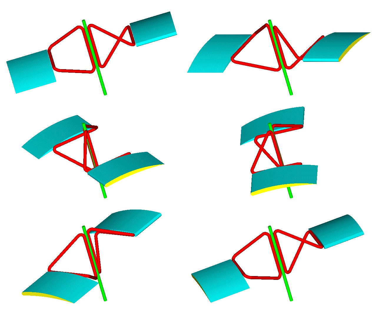
Here is another variable pitch propeller / rotor:
Image

Each red wire-frame "forms" a tetrahedron.


And here:
Image

Image

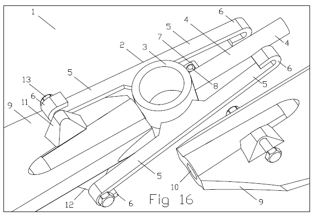
is apropeller / rotor comprising two blades and a hub.

The hub 2 comprises a center 3, two pins 4 and two pairs of flexible "skew" arms 5.
Each blade 9 has a hole / bearing 10 through which it is mounted on its respective pin 4 of the hub 2; each blade 9 has a pair of supports (like 11, 12 and 13), through which it is held by a pair of flexible "skew" arms 5.

The hub also comprises two stops 7, one per blade 9; the stop 7, with its bolt 8 prevents the respective blade from going to a pitch below a minimum; the stop also allows the preloading of the flexible arms.

At operation a shaft (or a sprocket, or a gearwheel etc) forces the propeller 1 to spin about a rotation axis. The blades 9 supported on respective pins 4 of the hub 2 are forced to follow the rotation of the hub about the rotation axis.

The centrifugal forces on the blades push them away from the rotation axis of the propeller; however the hooks 6 at the ends of the flexible arms 5 hold the blades 9 from moving away the rotation axis of the propeller.

Until an angular speed, the preloading of the flexible arms in combination with the stops ( 7 , 8 ) keep the blades at a minimum pitch.
Above an angular speed, the centrifugal force acting on each blade gets so strong that it pulls the blade slightly outwards (away from the propeller rotation axis), causing the bending of the flexible skew arms, which in turn causes the angular displacement of the blade about its long axis, which varies the pitch.

The higher the angular speed, the heavier the centrifugal force pulling each blade outwards, the larger the bending of the pair of flexible arms that hold the blade, the larger the angular displacement of the blade about its long axis (which, here, is the axis of the pin), and the bigger the pitch of the propeller.


With the pitch of the propellers of the Portable Flyer (first image in this post) being nearly 15" till 3,500rpm (of the propellers), with the pitch increasing to 40" at 4,000rpm (due to the centrifugal forces action) and to 45" above 4,500rpm (of the propellers) the power required from the engines lowers a lot, at emergency landings the healthy engine is not overloaded, the hovering duration extends a lot, the maximum speed goes beyond 300Km/h, etc, etc.

By the way:

Atan( 15" / (43" * pi) ) = 6.5 degrees,

Atan( 45" / (43" * pi) ) = 18.5 degrees.

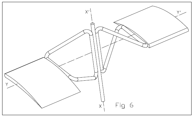
I.e. each blade needs to turn for only 12 degrees about its long axis ( Y - Y' in Fig. 6 ) in order the pitch to increase from 15" to 45".


More at https://www.pattakon.com/pattakonPitch.htm

Thanks
Manolis Pattakos

gruntguru
gruntguru
566
Joined: 21 Feb 2009, 07:43

Re: 2 stroke thread (with occasional F1 relevance!)

Post

Some of these concepts could be refined further if torque and/or thrust were introduced as inputs to the "pitch equation" by suitable location of the instant centres. The objective would be reducing pitch with increasing load.

The benefit would be higher rpm (and therefore higher power output) under heavily loaded conditions eg hover and emergency landing on a single engine. Then at cruise as load reduces, the pitch could increase allowing the engines to operate a lower rpm for higher efficiency and reliability.

Great concepts by the way. I particularly like #2 which is similar to #1 but utilising only flexures for movement.
je suis charlie

Tommy Cookers
Tommy Cookers
643
Joined: 17 Feb 2012, 16:55

Re: 2 stroke thread (with occasional F1 relevance!)

Post

gruntguru wrote:
20 May 2020, 02:36
Some of these concepts could be refined further if torque and/or thrust were introduced as inputs to the "pitch equation" by suitable location of the instant centres. The objective would be reducing pitch with increasing load.
The benefit would be higher rpm (and therefore higher power output) under heavily loaded conditions eg hover and emergency landing on a single engine. Then at cruise as load reduces, the pitch could increase allowing the engines to operate a lower rpm for higher efficiency and reliability....
this is what (fixed-wing) aviation has used for 80+ years in all except base-model aircraft
the aerodynamic equivalent of CVT
pilot-selected rpm modes giving motor:load torque relationship either for cruise economy or for max performance
this is aided by cruise mixture being as lean as possible and max performance mixture being rather rich


TO BE CONTD

gruntguru
gruntguru
566
Joined: 21 Feb 2009, 07:43

Re: 2 stroke thread (with occasional F1 relevance!)

Post

Tommy Cookers wrote:
20 May 2020, 09:32
gruntguru wrote:
20 May 2020, 02:36
Some of these concepts could be refined further if torque and/or thrust were introduced as inputs to the "pitch equation" by suitable location of the instant centres. The objective would be reducing pitch with increasing load.
The benefit would be higher rpm (and therefore higher power output) under heavily loaded conditions eg hover and emergency landing on a single engine. Then at cruise as load reduces, the pitch could increase allowing the engines to operate a lower rpm for higher efficiency and reliability....
this is what (fixed-wing) aviation has used for 80+ years in all except base-model aircraft
the aerodynamic equivalent of CVT
pilot-selected rpm modes giving motor:load torque relationship either for cruise economy or for max performance
this is aided by cruise mixture being as lean as possible and max performance mixture being rather rich
Yes but they would all be active systems controlling pitch to achieve an rpm set-point?

What I am suggesting is a passive system.
je suis charlie

Tommy Cookers
Tommy Cookers
643
Joined: 17 Feb 2012, 16:55

Re: 2 stroke thread (with occasional F1 relevance!)

Post

for serious aircraft - a passive system can't feather

for trivial aircraft passive 'semi-VP' composite props do exist (or is this eg motor paragliders or something similar ???)
though for most there's little benefit as speed is limited by falling wing L:D ratio as Cl is reduced with speed increase and ..
going lean for cruise (with 4 strokes anyway) acts in effect as a free VP system and ...
take-off doesn't benefit much as Froude efficiency is the dominant factor and ...
improved take-off is pointless as landing distance then dominates

my earlier suggestion of (structurally-tailored composite prop design) was of relevance to the PF
the PF is an unusual case - because it benefits from/needs some VP
(though full VP aka 'constant speed' isn't vital at this point in its development)

btw M P
both helicopters and aeroplanes need less engine power as speed increases from minimum
a helicopter has immutable CS ie fixed rotor rpm - power is slaved to pitch demanded and maximal in hover (HOGE anyway)
does anyone want rotors for some home-designed helicopter using variable rotor rpm ??

manolis
manolis
107
Joined: 18 Mar 2014, 10:00

Re: 2 stroke thread (with occasional F1 relevance!)

Post

Hello Tommy Cookers.

The idea is to have a small pitch at low revs (to take off, land and hover), and then to increase significantly the pitch with the revs in order to cruise at high speeds without overloading the engine(s).

The low pitch is important especially for emergency landings wherein the healthy engine must not be overstressed.

Like having a CVT (continuously variable transmission), as you wrote.

Image

The question is:

Are there available such "automatically variable pitch" (in a wide range variable) propellers, or do I need to build them?

Thanks
Manolis Pattakos
Tommy Cookers
Tommy Cookers
643
Joined: 17 Feb 2012, 16:55

Re: 2 stroke thread (with occasional F1 relevance!)

Post

yes they are available
https://www.kitplanes.com/propeller-buyers-guide/

the DUC Swirl may be the sort of concept I had in mind
the Aeromatic seems to have been in the 1940s a passive system as other recent posters here have suggested

anyway novel active systems (for low-powered engines) now seem to be available
some even in hub-only form suitable for customers to source their blades

and ground-adjustable pitch is the feature now very widely offered (for home-built aircraft)
I assume this to be setting the prop pitch 'in the workshop' to match the application


btw
if 15" 6.5 degree pitch means geometric pitch (ie installed angle) .... is this enough ?
even in hover won't the airstream velocity reduce the effective AoA far below 6.5 deg ?

manolis
manolis
107
Joined: 18 Mar 2014, 10:00

Re: 2 stroke thread (with occasional F1 relevance!)

Post

Hello Tommy Cookers.

You write:
“if 15" 6.5 degree pitch means geometric pitch (ie installed angle) .... is this enough ?
even in hover won't the airstream velocity reduce the effective AoA far below 6.5 deg ?”


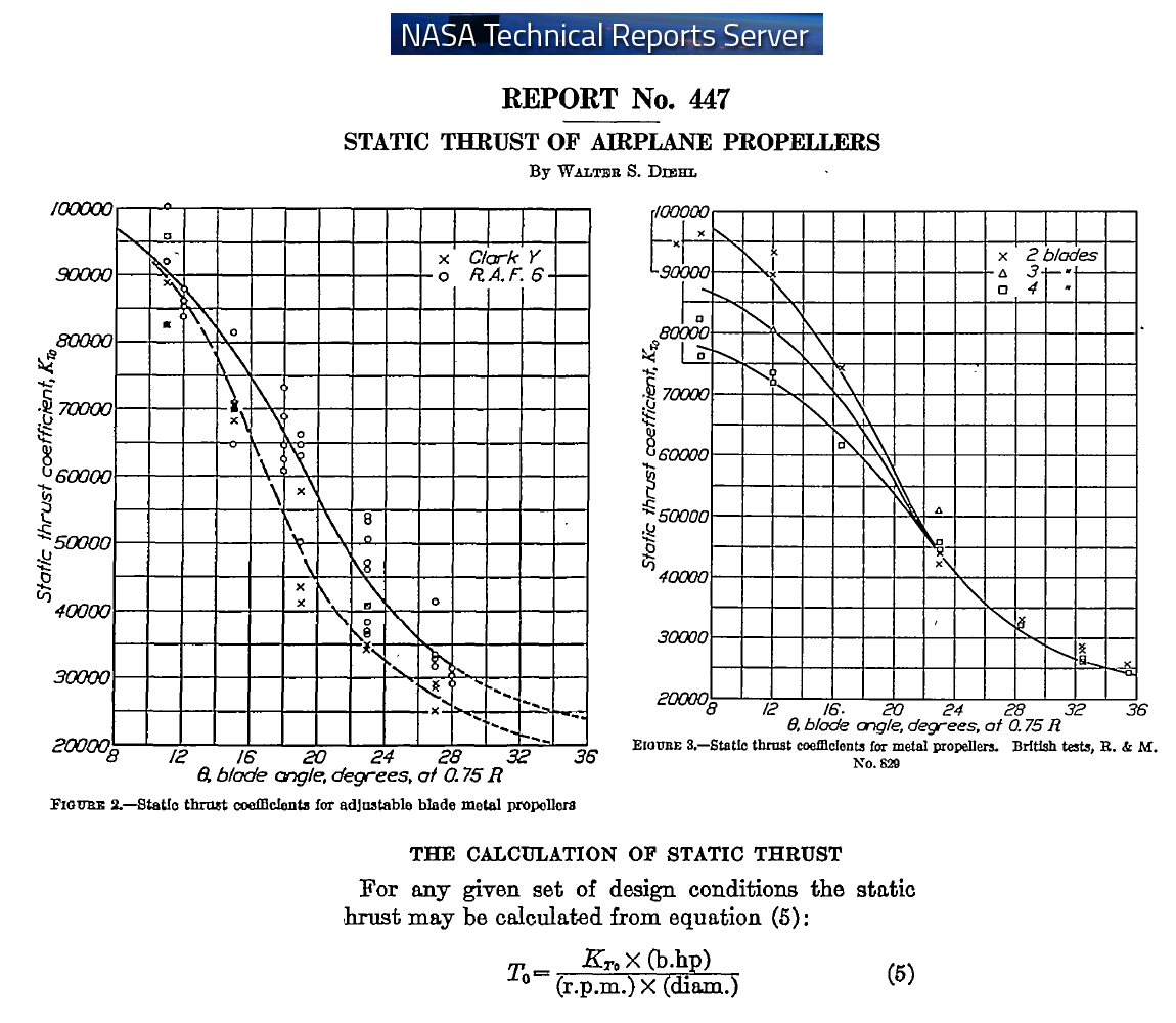
The complete pdf document is at https://ntrs.nasa.gov/archive/nasa/casi ... 091521.pdf :

Image


The formula at the bottom of the image says that the static thrust is directly proportional to the power and is inversely proportional to the revs (in other words, the static thrust is directly proportional to the torque applied to the propeller).

The static thrust coefficient increases substantially at smaller “geometrical” blade angles.


Case 1:

With 8 degrees blade angle (at 0.75R), a 43” diameter propeller has:

Atan( tan(8) * 0.75 ) = 6 degrees blade angle at 1.0R,

which gives a propeller pitch of: tan(6)*43”*pi=14”


Case 2:

With 20 degrees blade angle (at 0.75R), the same propeller has:

Atan( tan(20) * 0.75 ) = 15 degrees blade angle at 1.0R,

which gives a propeller pitch of: tan(15)*43”*pi=37”


The static thrust coefficient halves in the second case (Figure 2).

The formula says that for the same static thrust and the same revs (rpm), the 43” propeller will consume in the second case (37”pitch) two times the power it consumes in the first case (14” pitch).

The formula also says that applying the same torque to the propeller, the static thrust halves in the second case (37”pitch) as compared to the first case (14”pitch).


I think the previous reply to your question.


You also write:
“the Aeromatic seems to have been in the 1940s a passive system as other recent posters here have suggested”


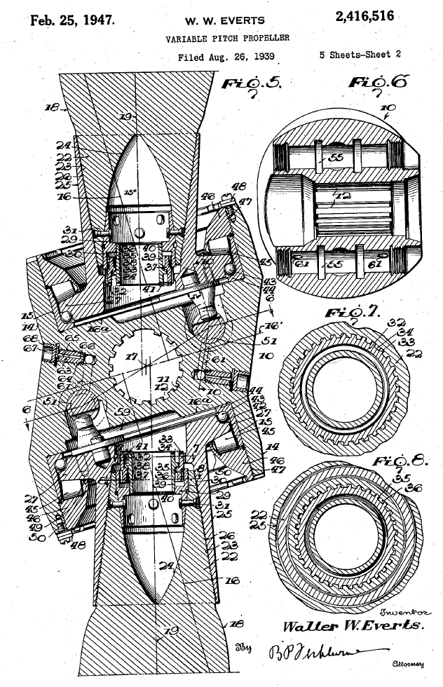
At https://www.pattakon.com/Pitch/US_2134661_Aeromatic.pdf and at https://www.pattakon.com/Pitch/US_2416516_Aeromatic.pdf there are two US patents granted for the Aeromatic propellers:

Image

The Aeromatic design seems too heavy (count the number of heavy bearings required) and too complicated for the Portable Flyer.

Thanks
Manolis Pattakos
Tommy Cookers
Tommy Cookers
643
Joined: 17 Feb 2012, 16:55

Re: 2 stroke thread (with occasional F1 relevance!)

Post

Tommy Cookers wrote:
21 May 2020, 10:15
if 15" 6.5 degree pitch means geometric pitch (ie installed angle) .... is this enough ?
even in hover won't the airstream velocity reduce the effective AoA far below 6.5 deg ?
yes ok MP I now agree that pitch is enough
(the Diehl paper seems valuable in that regard)
enough particularly as a tailslide would be more problematic to a prop with a greater geometric pitch
(as the reversal of incoming air vector could increase the aerodynamic pitch eg beyond the 'stalling angle')


regarding the PatPitch propeller design ....

the blades have some 'natural' frequency of oscillation pitchwise due to their compliant mounting on their spindles and ...
cyclic variation of blade AoA/pitching moment as the PF's 'body attitude' is significantly different to its direction of motion
(unlike other aircraft)
so unless otherwise designed might develop excessive and/or sustained blade-on-spindle oscillation ?

also - isn't a lot of engine rpm change required ??
(to give the chosen pitch change)

manolis
manolis
107
Joined: 18 Mar 2014, 10:00

Re: 2 stroke thread (with occasional F1 relevance!)

Post

Hello all.

The following explain how the PatPitch works.

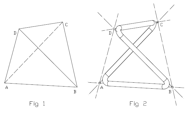
Starting with a regular tetrahedron (Fig. 1)

Image

a wire-frame is formed following four from its six edges (Fig. 2).

A characteristic of the tetrahedron is that each pair of “opposite” (non intersecting) edges are skew lines.

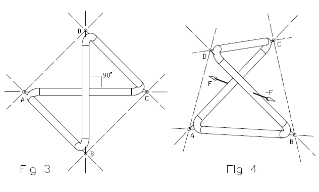
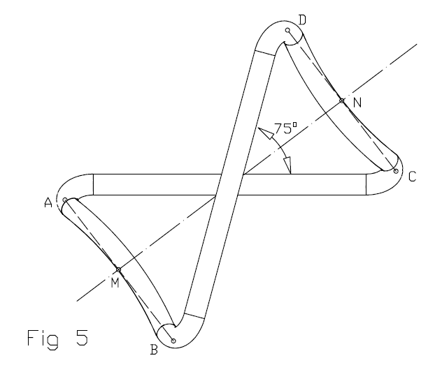
Looking from a viewpoint on the line connecting the midpoints of the AC and BD line segments, the angle between the edges AC and BD appears orthogonal (90 degrees, Fig. 3):

Image

In Fig. 4 two collinear forces F and –F load the pair of skew edges / arms AC and BD of the wire frame of Figs. 2 and 3; the wire frame is considered inflexible.

With the edges / arms AB and CD of the wire frame being flexible, Fig. 5 shows the deformation of the wire-frame due to the forces F and –F of Fig. 4.

Image

Looking from a viewpoint on the line connecting the midpoints of the AC and BD line segments, the angle between the edges AC and BD is now far from orthogonal (it is shown as 75 degrees); that is, the loading of the wire frame by the F, -F forces causes an angular deformation.

The line segment AB connecting the ends of the one flexible arm and the line segment CD connecting the ends of the other flexible arm are skew lines.

When looked from a viewpoint on the line MN connecting their midpoints (M is the midpoint of the line segment AB, N is the midpoint of the line segment CD), they form a wide (substantially different than zero) angle.

Exploiting this kind of angular deformation, the propeller of Fig. 6 is made (the blades are properly sliced / cut to fit in the drawing).

Image

It comprises two wire frames (as those of Figs. 2 to 5, red in the following animation) and two blades.

Each wire-frame is secured by one of its arms on the propeller shaft, and by the opposite (skew) arm on a blade; the remaining pair of “free” flexible arms of the wire-frame gives angular flexibility to the connection between the propeller shaft and the blade.

Image


Compare the “mechanism” of the Aeromatic propellers with the “mechanism” (?) of the PatPitch propeller, their weight, space requirement, cost etc...

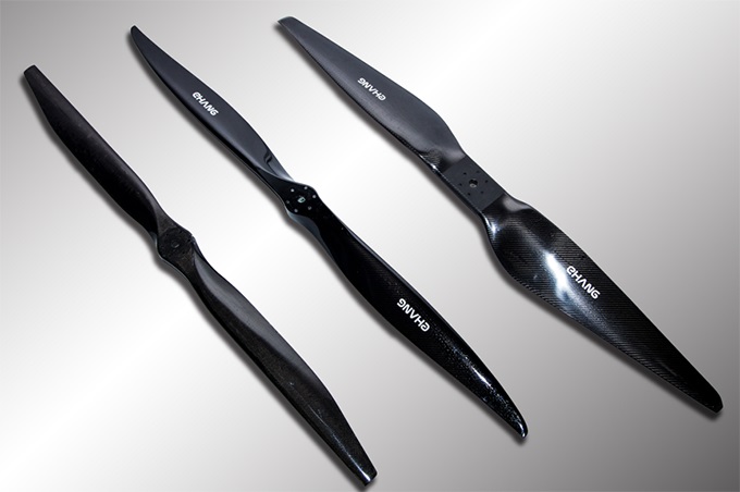
And think the advantages the PatPitch propellers can bring to Flying Devices like the Ehang 841 (here are the proppellers they used, the older design at left, the last design at right):

Image

the air taxis in general, the drones (big and small ones), etc, etc.

Thanks
Manolis Pattakos
Last edited by manolis on 24 May 2020, 08:59, edited 1 time in total.

manolis
manolis
107
Joined: 18 Mar 2014, 10:00

Re: 2 stroke thread (with occasional F1 relevance!)

Post

Hello Tommy Cookers

You write:
  • “regarding the PatPitch propeller design ....

    the blades have some 'natural' frequency of oscillation pitchwise due to their compliant mounting on their spindles and ...
    cyclic variation of blade AoA/pitching moment as the PF's 'body attitude' is significantly different to its direction of motion
    (unlike other aircraft)
    so unless otherwise designed might develop excessive and/or sustained blade-on-spindle oscillation ?”


The blades of the Portable Flyer are short (~500mm), they are lightweight and inflexible.

All these increase a lot the natural frequency of pitchwise oscillations.

The mounting of each blade (last post) is “inflexible”, too.

Let me explain using some numbers / calculations:

Suppose each blade weighs 0.2Kg (carbon fibers) and its center of gravity has an eccentricity of 250mm (i.e. 0.25m) relative to the propeller rotation axis.

At 4,000 rpm (i.e. 4,000/60 = 67 rounds per second), the tetrahedron that holds the blade receives a centrifugal force of:

0.2Kg * ((0.25m*2*pi)*67/sec)^2 / 0.25m = 8,850N (885Kgf, 1,950lbf)

This “extreme” force (as compared to the weight of the blade) flexes the two “free” arms of the tetrahedron and varies the pitch.

At high speed cruising, the aerodynamic force (lift or thrust) on each blade (there are 8 or 12 blades, depending on the number of blades per propeller) is about 80Nt (8Kgf, 18lb) and acts at a small eccentricity relative to blade’s long axis; if you take under account the way the blade is mounted (tetrahedron) and the size of forces on blade’s mounts, the aerodynamic force on the blade cannot vary noticeably its angular displacement about its long axis (i.e. the pitch).


You also write:
  • “also - isn't a lot of engine rpm change required ??
    (to give the chosen pitch change)”

The OPRE Tilting engines of the PortableFLyer are to operate:

from 2.4*2,500=6,000rpm (6m/sec mean piston speed) and partial load (slow take off, landing, hovering, loitering),

to 2.4*3,500=8,400rpm (8.4m/sec mean piston speed) in case of emergency landing with the healthy engine running at medium load,

to 2.4*4000=9,600rpm (9.6m/sec mean piston speed) to cruise horizontally at 250Km/h, with the engine running at medium load and the pilot not suffering from the air.

Occasionally the engines can rev up to 11,000rpm (11m/sec mean piston speed) to allow cruising speeds over 300Km/h.

Image

The characteristics of the OPRE Tilting engine:
  • short piston stroke,
  • extra piston dwell at the combustion dead center for efficient combustion at higher revs,
  • built-in tilting valves for the control of the air fuel mixture,
  • perfect balance (vibration-free quality)
  • etc
fit with the previously described operational range.

Thanks
Manolis Pattakos

J.A.W.
J.A.W.
109
Joined: 01 Sep 2014, 05:10
Location: Altair IV.

Re: 2 stroke thread (with occasional F1 relevance!)

Post

Well done Manolis, on the patent.

You may find something of interest in this recent paper on 2T OP engine tech.

https://www.mdpi.com/1996-1073/11/4/940/htm

As for your 'wire' flex-pitch prop design, ~1/2 a century ago
BSA/Triumph motorcycles went to the use of 'wire' mounting styled
front mudguard & headlight supports, but found that even rubber damped
wire would resonate, & eventually then fatigue-fracture due to vibration
frequency inputs from both engine & road effects.

Image


Perhaps a damper for resonance-harmonics control of vibration from both
engine & rotational aerodynamic frequency effects may be required?

A variable thickness, &/or hollow, internally damped 'wire',
or even a torque-tube/quill-mount set up of some kind?
"Well, we knocked the bastard off!"

Ed Hilary on being 1st to top Mt Everest,
(& 1st to do a surface traverse across Antarctica,
in good Kiwi style - riding a Massey Ferguson farm
tractor - with a few extemporised mod's to hack the task).

Tommy Cookers
Tommy Cookers
643
Joined: 17 Feb 2012, 16:55

Re: 2 stroke thread (with occasional F1 relevance!)

Post

the Ehang seems to be opposite to the PF regarding its need for variable pitch

the PF needs a lot of VP - to allow high flight speed combined with low (each engine) power in hover
and pays for this in needing to design for a big rpm range

and the PatPitch seems unsuited to conventional aircraft
Last edited by Tommy Cookers on 25 May 2020, 22:00, edited 2 times in total.

Tommy Cookers
Tommy Cookers
643
Joined: 17 Feb 2012, 16:55

Re: 2 stroke thread (with occasional F1 relevance!)

Post

manolis wrote:
24 May 2020, 06:04
A ....At 4,000 rpm (i.e. 4,000/60 = 67 rounds per second), the tetrahedron that holds the blade receives a centrifugal force of:
0.2Kg * ((0.25m*2*pi)*67/sec)^2 / 0.25m = 8,850N (885Kgf, 1,950lbf)
This “extreme” force (as compared to the weight of the blade) flexes the two “free” arms of the tetrahedron and varies the pitch.
it is not this force that varies the pitch

whatever the type of structural linkage (tetrahedral or leaf spring/flexure) the PP uses to handle the centrifugal force ..
the pitch is varied by the components (of linkage forces) in the plane of rotation about the blade-mounting spindles
said force components producing rotation in pitch are small relative to the centrifugal force
eg if a stationary blade had 1950 lbf applied (by external cable) wouldn't the PP be perceptibly compliant ?

so oscillation in pitch including possible resonance and aero effects isn't clearly implausible