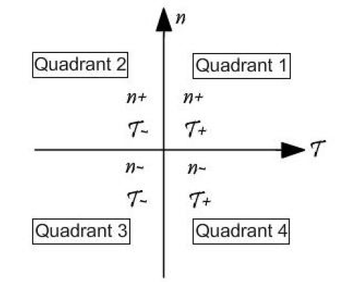
To get regenerative operation of a drive you need operation in four quadrant, that is a bidirectional energy flow. We will assume a induction machine for simplicity.
Four quadrant operation relates to the signs of the speed (n) and torque (t).
First quadrant: Positive torque, positive speed.
Motor fed by the batteries.
Second quadrant: Negative torque, positive speed.
Motor is braking and energy returns to batteries.
Third quadrant: Negative torque, negative speed.
Motor fed by batteries but backwards movement.
Fourth quadrant: Positive torque, negative speed.
Motor is braking, energy returning to batteries in backward movement.
It seems that only first and second quadrant should be needed in a KERS.

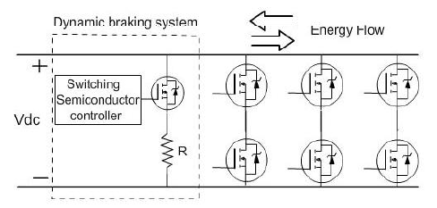
Changing the torque/speed references of the controller makes possible the regenerative operation of the bidirectional rectifier/inverter.
The converter used for this operation could be a bidirectional 6 switch bridge.

DC Side (left) is where batteries should be connected (or supercapacitors, flywheels or other DC storage) and AC side is where you put the motor/generator (right).
Its not clear in the drawing but the motor is connected in the middle points between the switches.
A three phase connection is used due to the big power transfer. A single phase converter need less components, but a semiconductor for this application could be non existant.
The dynamic braking system in the figure is there to absorb overcharging of the dc bus and acts as chopper regulating dc link instantaneous voltage. In this way excess power flow is burnt in the resistor in series with the switch.
I hope that this is useful for something... i just wanted to contribute something for the lots of things that i learn here related to mechanics

Note that the topology should be similar for a permanent magnet motor, but the control of the switches will change. If i have more time i will write something about it.
Regards
"We will have to wait and see".


