2 stroke thread (with occasional F1 relevance!)

All that has to do with the power train, gearbox, clutch, fuels and lubricants, etc. Generally the mechanical side of Formula One.
manolis
manolis
107
Joined: 18 Mar 2014, 10:00

Re: 2 stroke thread (with occasional F1 relevance!)

Post

Hello Tommy Cookers.

You write:

Quote from https://www.forza-mag.com/issues/154/ar ... ity-clause

Alfa Romeo Bimotore 1935

Image

Some more details:

Image

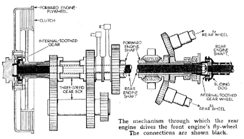
All this "complexity" was necessary in order to utilize two long engines: an in-line 8-cylinder engine in front of the driver and another in-line 8-cylinder engine behind the driver, with a common gearbox / differential at the middle of the car (the drive wheels were the rear wheels).

I can't see how this architecture affects the inertia torque on the engine casing.


You also write:
  • the point of the Mercedes axle is that each wheel/road contact load is unaffected by the engine power being used

Sorry but, again, I can’t get how the Mercedes axle eliminates the inertia torque on the engine casing and on the frame of the car.

A drawing / plot / photo would help.

Thanks
Manolis Pattakos

User avatar
Zynerji
110
Joined: 27 Jan 2016, 16:14

Re: 2 stroke thread (with occasional F1 relevance!)

Post

Mudflap wrote:
12 Dec 2020, 03:49
Hi Manolis,

See below a similar concept where the kinematics can be adjusted on the fly to reduce any order. Probably not much use in flatplane l4 where the 2nd order appears to dominate in most practical situations but more appropriate for engine configurations where the dominating excitation changes between inertia torques and gas pressure torques with engine speed.

https://www.google.com/url?sa=t&source= ... 27jRhp3VoZ
Doesn't the MGU-K do this in F1 now? I always thought the K would go into "recovery" mode at certain parts of rotation to counteract these harmonics...🤔

Tommy Cookers
Tommy Cookers
643
Joined: 17 Feb 2012, 16:55

Re: 2 stroke thread (with occasional F1 relevance!)

Post

Zynerji wrote:
08 Jan 2021, 06:21
Mudflap wrote:
12 Dec 2020, 03:49
Hi Manolis,
See below a similar concept where the kinematics can be adjusted on the fly to reduce any order. Probably not much use in flatplane l4 where the 2nd order appears to dominate in most practical situations but more appropriate for engine configurations where the dominating excitation changes between inertia torques and gas pressure torques with engine speed.
https://www.google.com/url?sa=t&source= ... 27jRhp3VoZ
Doesn't the MGU-K do this in F1 now? I always thought the K would go into "recovery" mode at certain parts of rotation to counteract these harmonics...🤔
it could do something at 1200 crankshaft rpm but seemingly little or nothing at 12000 crankshaft rpm

the K frequency response (wrt self and external load) limit will be about 5 Hz
but the K could be used as an active damper (of an externally-forced cycle)
because the K torque can always respond quicker if the K's not accelerating or decelerating itself


the recovery of the existing passive mechanical (isolation) effects under the conditions of interest is maybe 99.7%

are people thinking of an inline-4 F1 engine ?

NOTE to self - a '3 Hz' system I remember had its 1st order pole designed to 5 Hz (and a '2 Hz' was designed to 3 Hz)
Last edited by Tommy Cookers on 11 Jan 2021, 13:03, edited 3 times in total.

User avatar
Zynerji
110
Joined: 27 Jan 2016, 16:14

Re: 2 stroke thread (with occasional F1 relevance!)

Post

Honda said theirs switched 40Hz. Is that really too slow to have this effect? Maybe I'm remembering the MGUH numbers...

63l8qrrfy6
63l8qrrfy6
368
Joined: 17 Feb 2016, 21:36

Re: 2 stroke thread (with occasional F1 relevance!)

Post

The switching frequency is not the same as the torque control frequency.
PMSMs can and are sometimes used for active torsional vibration control at low frequencies (100s of hz)

Tommy Cookers
Tommy Cookers
643
Joined: 17 Feb 2012, 16:55

Re: 2 stroke thread (with occasional F1 relevance!)

Post

K generation equivalent to 40 Hz works as the rate of change of rpm applied by the ICE to the K is acceptable to the K
(ie the electric 'time constant' is small enough to allow 40 Hz - but the electromechanical 'time constant' wouldn't be)

the K won't do the job under discussion if the rate of change of rpm applied by the ICE to the K is unacceptable to the K
ie the K hasn't enough load rejection capability

a K-style electromagnetic 'inertial force absorber' is 95% efficient - a mechanical 'absorber' is eg 99.7% efficient
there's little or no 'inertial force' available to be absorbed in eg an F1 90 deg V6


regarding the Mercedes-style axle (eg in the Bimotore) ....
the axle is unrelated to the twin engines - it was used earlier (as I said) in the Tipo B cars
the twin CWPs appeared in 1914 in what was the first Mercedes GP propshaft-driven axle (1913 M GPs used chain drive)
the twin CWPs were (then) apparently to allow (positive) camber to match perfectly the road camber
we can still wonder what (the honorary Dr and onetime Merc TD) Porsche did for the Mercedes axle design pre 1924
my view (on the axle's USP) came iirc (via sources eg Pomeroy, Clutton ?, and Karslake) from the Posthumous book
eg Pomeroy's book has only the 1914 car
btw Mercedes and Benz nominally had some co-operation from 1924 but actually merged in 1926

manolis
manolis
107
Joined: 18 Mar 2014, 10:00

Re: 2 stroke thread (with occasional F1 relevance!)

Post

Hello Zynerji

You write:
  • "Doesn't the MGU-K do this in F1 now? I always thought the K would go into "recovery" mode at certain parts of rotation to counteract these harmonics..."
    and
    "Honda said theirs switched 40Hz. Is that really too slow to have this effect? Maybe I'm remembering the MGUH numbers..."

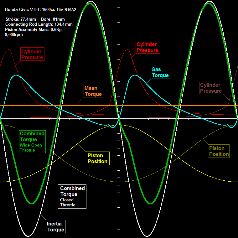
The plot at the top of the last page:

Image

explains the case.

The gas torque (cyan curve), i.e. the (per crank rotation) mechanical energy provided to the set of the four pistons by the working gas, is seven times (or so) smaller than the inertia torque (white curve), i.e. seven times smaller than the (idling) mechanical energy oscillating between the set of the four pistons and the crankshaft / flywheel / transmission / drive wheels.

Subtracting the gas torque from the inertia torque, it results the combined torque (green curve). The green and white curves are similar in size and shape (i.e. the "counteraction" from the gas is too small).

As for the mechanical energy that can be "milked" from the exhaust gas, it is smaller than the mechanical energy provided by the gas to the pistons.


Regarding the frequency:

At 9,000rpm (i.e. at 9,000/60=150 crank rotations per second, i.e. at 150Hz) where the 1600cc four-cylinder engine operates in the video, the frequency of the inertia torque is 2*150Hz=300Hz.


So, it is not only that the energy contained in the gas (and in the exhaust gas) is too small to seriously counteract (somehow) the inertia torque, but it is also that the required frequency of the "counteraction" is too high to be impemented by some kind of "MGU-K".

Thanks
Manolis Pattakos

J.A.W.
J.A.W.
109
Joined: 01 Sep 2014, 05:10
Location: Altair IV.

Re: 2 stroke thread (with occasional F1 relevance!)

Post

Have any hi-performance 2T designs considered/utilized this set-up from ram-jet
practice, with an (external coolant fed) 'bullet' placed in the throat of the exhaust,
so as to prevent the near sonic 'choke' of flow, (but not overheat the return pulse,
perhaps by a timed shot of refrigerant, recycled through a heat-exchanger?)

A moveable device might accommodate flow rates for max-output over an rpm range?

Scroll across to 1:25 in this vid, to see a graphic of the internal 'shock-body':

"Well, we knocked the bastard off!"

Ed Hilary on being 1st to top Mt Everest,
(& 1st to do a surface traverse across Antarctica,
in good Kiwi style - riding a Massey Ferguson farm
tractor - with a few extemporised mod's to hack the task).

manolis
manolis
107
Joined: 18 Mar 2014, 10:00

Re: 2 stroke thread (with occasional F1 relevance!)

Post

Hello J.A.W.

You write:
"Have any hi-performance 2T designs considered/utilized this set-up from ram-jet
practice, . . .
A moveable device might accommodate flow rates for max-output over an rpm range? "


Here is a two-stroke design wherein by throttling / restricting the exhaust end (exhaust throat), the power output can be increased:


Quote from page 232:

For instance, think the PatOP wherein the scavenge pump capacity is 850cc while the cylinder capacity is only 635cc (scavenge ratio: 850cc/635cc = 1.34).
It doesn't matter it is a Diesel. It could operate as a carbureted 2-stroke petrol, too.

Here it is shown the big bore of the built-in scavenge pump of the PatOP, more at https://www.pattakon.com/pattakonPatOP.htm ) :
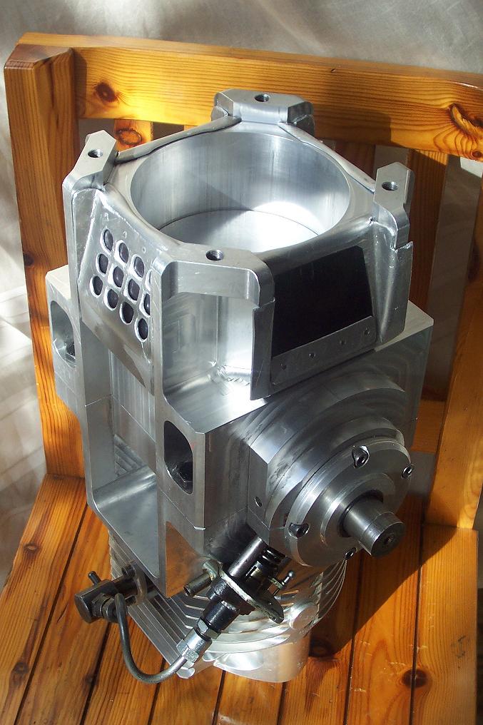
Image

Normally the exhaust ports close after the transfer ports.

So the surplus of air in the cylinder escapes through the exhaust (this is not bad if you think that the additional air, among others, cools down the exhaust piston crown and the exhaust ports on the cylinder).

But if you put a restriction / an obstacle at the end of the exhaust pipe, you can keep the pressure of the exhaust substantially higher than ambient (say, at 1.3 bar when the exhaust ports finally close). Yes, the scavenge pump will absorb more power from the crankshaft, however the trapped air in the cylinder will be much more than 635cc (nearly 850cc) and the power output will increase substantially.

End of Quote.


In the following photo it is shown the diameter of the combustion cylinder versus the diameter of the scavenge pump cylinder:
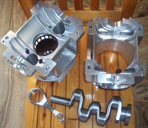
Image

The overall stroke in the combustion cylinder is 64+64=128mm versus the only 64mm stroke of the scavenge piston, however the bore of the combustion cylinder is only 79.5mm while the bore of the scavenge cylinder is 130mm, resulting in a scavenge ratio of:

Scavenge Ratio = (64 * 130^2) / (128 * 79.5^2)=1.34

By putting a displaceable 'bullet' (ram-jet, as in your post) in the throat of the PatOP exhaust (or any other kind of throttle), substantially more fresh air can be trapped into the cylinder allowing more fuel to be injected and burnt (and so more output power to be provided).

Thanks
Manolis Pattakos

Brake Horse Power
Brake Horse Power
18
Joined: 25 Oct 2017, 21:36

Re: 2 stroke thread (with occasional F1 relevance!)

Post

Nicely made engine block you got there! 👌👌

Another project i came across (again) is this guy working on a 50cc engine with oval exhaust port at 100% of cylinder bore width. Radical transfers, head, exhaust channel. Well basically everything
Was

https://youtu.be/c92CQuHdP1Q

J.A.W.
J.A.W.
109
Joined: 01 Sep 2014, 05:10
Location: Altair IV.

Re: 2 stroke thread (with occasional F1 relevance!)

Post

manolis wrote:
25 Feb 2021, 07:25
Hello J.A.W.

You write:
"Have any hi-performance 2T designs considered/utilized this set-up from ram-jet
practice, . . .
A moveable device might accommodate flow rates for max-output over an rpm range? "


Here is a two-stroke design wherein by throttling / restricting the exhaust end (exhaust throat), the power output can be increased:


Quote from page 232:

For instance, think the PatOP wherein the scavenge pump capacity is 850cc while the cylinder capacity is only 635cc (scavenge ratio: 850cc/635cc = 1.34).
It doesn't matter it is a Diesel. It could operate as a carbureted 2-stroke petrol, too.

Here it is shown the big bore of the built-in scavenge pump of the PatOP, more at https://www.pattakon.com/pattakonPatOP.htm ) :

https://www.pattakon.com/patop/PatOPpro4.jpg

Normally the exhaust ports close after the transfer ports.

So the surplus of air in the cylinder escapes through the exhaust (this is not bad if you think that the additional air, among others, cools down the exhaust piston crown and the exhaust ports on the cylinder).

But if you put a restriction / an obstacle at the end of the exhaust pipe, you can keep the pressure of the exhaust substantially higher than ambient (say, at 1.3 bar when the exhaust ports finally close). Yes, the scavenge pump will absorb more power from the crankshaft, however the trapped air in the cylinder will be much more than 635cc (nearly 850cc) and the power output will increase substantially.

End of Quote.


In the following photo it is shown the diameter of the combustion cylinder versus the diameter of the scavenge pump cylinder:

https://www.pattakon.com/patop/PatOPpro2.jpg

The overall stroke in the combustion cylinder is 64+64=128mm versus the only 64mm stroke of the scavenge piston, however the bore of the combustion cylinder is only 79.5mm while the bore of the scavenge cylinder is 130mm, resulting in a scavenge ratio of:

Scavenge Ratio = (64 * 130^2) / (128 * 79.5^2)=1.34

By putting a displaceable 'bullet' (ram-jet, as in your post) in the throat of the PatOP exhaust (or any other kind of throttle), substantially more fresh air can be trapped into the cylinder allowing more fuel to be injected and burnt (and so more output power to be provided).

Thanks
Manolis Pattakos
Thanks for the consideration/reply Manolis.

I expect that an exhaust port-obtunding timed 'bullet' shape design-flow factored to
prevent 'sonic-choke' in high-Mach port-flows could be fitted in multiples, as might be
required by the number of ports (& timed/staged accordingly as well), & yet may even
be usefully constructed from a ceramic-foam matrix - which will not tend to retain/transfer
any unwanted exhaust heat via the 2T return boost-flow pulse - in an expansion chamber pipe.
"Well, we knocked the bastard off!"

Ed Hilary on being 1st to top Mt Everest,
(& 1st to do a surface traverse across Antarctica,
in good Kiwi style - riding a Massey Ferguson farm
tractor - with a few extemporised mod's to hack the task).

manolis
manolis
107
Joined: 18 Mar 2014, 10:00

Re: 2 stroke thread (with occasional F1 relevance!)

Post

Hello J.A.W.

And if the movable / controllable "bullet(s)" are used to add (and remove) additional volumes / lengths to the basic exhaust chamber?

Wouldn't the exhaust resonate at a wider range of revs (and loads)?

Thanks
Manolis Pattakos

J.A.W.
J.A.W.
109
Joined: 01 Sep 2014, 05:10
Location: Altair IV.

Re: 2 stroke thread (with occasional F1 relevance!)

Post

manolis wrote:
02 Mar 2021, 05:59
Hello J.A.W.

And if the movable / controllable "bullet(s)" are used to add (and remove) additional volumes / lengths to the basic exhaust chamber?

Wouldn't the exhaust resonate at a wider range of revs (and loads)?

Thanks
Manolis Pattakos
Hi Manolis, that should be a reasonable expectation, but of course pressure/pulse-effects
must also be duly factored in, for utilization as advantageous/nullification when not.

Perhaps internal cones of the ceramic-matrix material within the pipe might withstand
potential fatigue fractures (due to the pulse/pressure waves), or may be used as a kind of
sleeve, or cone-valve to open & close ports within a double-skinned exhaust, or even as a
'blind' (yet mobile) inner-skin, utilizing the both the pulses to 'power' timed movement, plus
offering the heat-rejection differential (exhaust gas temp) for sonic frequency tuning?
"Well, we knocked the bastard off!"

Ed Hilary on being 1st to top Mt Everest,
(& 1st to do a surface traverse across Antarctica,
in good Kiwi style - riding a Massey Ferguson farm
tractor - with a few extemporised mod's to hack the task).

manolis
manolis
107
Joined: 18 Mar 2014, 10:00

Re: 2 stroke thread (with occasional F1 relevance!)

Post

Hello J.A.W.

You write:

  • Perhaps internal cones of the ceramic-matrix material within the pipe might withstand potential fatigue fractures (due to the pulse/pressure waves), or may be used as a kind of sleeve, or cone-valve to open & close ports within a double-skinned exhaust, or even as a 'blind' (yet mobile) inner-skin, utilizing the both the pulses to 'power' timed movement, plus offering the heat-rejection differential (exhaust gas temp) for sonic frequency tuning?


All these can, reasonably, improve the operation of the 2-stroke.

However the added complexity, cost and weight may cancel out the main advantages of the 2-stroke: simplicity, low cost, lightweight and compactness.


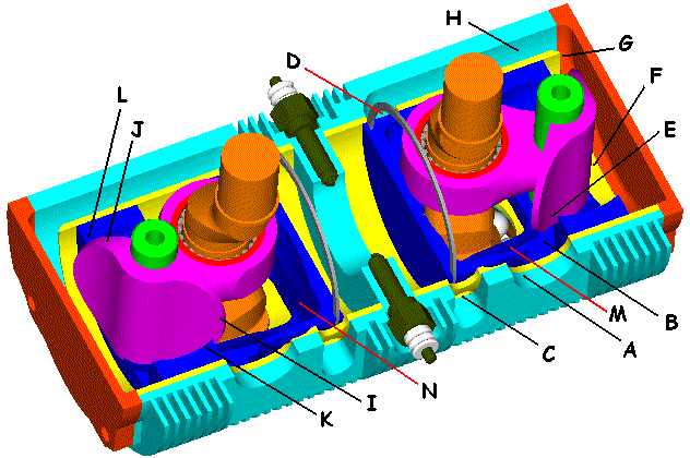
In the case of the unconventional OPRE_Tilting:

Image

(more at https://www.pattakon.com/pattakonTilting.htm )

the transfer does, more or less, what the exhaust in the conventional 2-stroke:


Quote from https://www.pattakon.com/tilting/pattak ... s_FLow.htm
  • TUNING

    The "tuning" depends more on the intake and transfer, than on the exhaust.

    With the exhaust ports already opened, the transfer ports open and the scavenging begins.
    The transfer ports open earlier than in a conventional 2-stroke. The pressure into the "scavenge pump" (sealed by the "back-side" of the piston whereon the tilting valve is still closed) allows such timing.

    Later the tilting valve opens and the scavenging continues based on the inertia of the gas column formed along:
    the open tilting-valve-port on the piston,
    the space into the scavenge pump,
    the transfer passageways,
    the transfer ports,
    the combustion chamber,
    the exhaust ports,
    and the exhaust.

    Fresh charge from the "crankcase" (i.e. from the space inside the piston) feeds this "inertia" column, while the crankcase is fed from the intake, through the intake port, with fresh charge (air-fuel-oil mixture).

    When the piston finally closes the transfer ports, the suction of air-fuel-oil-mixture from the intake continues due partly to the sub-pressure created into the scavenge pump space as the piston (with the tilting valve open) moves towards the TDC, and partly to the inertia of the gas column formed along:
    the intake,
    the intake port,
    the crankcase,
    the scavenge pump space,
    and the scavenge passageways.

    After the TDC the tilting valve closes and the air-fuel-oil-mixture trapped inside the "scavenge pump" is compressed waiting the transfer ports to open again by the piston.
    And so on.

With the specific energy (energy to weight ratio, typically in kWh/Kg) of the contemporary batteries being several times lower than the specific energy of the HydroCarbon fuels, the flying vehicles / devices will continue to need internal combustion engines, especially those with higher specific power (power to weight ratio, typically in kW/Kg, with the weight of the required fuel for a specific range included), like the two strokes:


Thanks
Manolis Pattakos

J.A.W.
J.A.W.
109
Joined: 01 Sep 2014, 05:10
Location: Altair IV.

Re: 2 stroke thread (with occasional F1 relevance!)

Post

Hi Manolis, no designer who is serious about improving the high-performance S.I. 2T,
can blithely ignore the tremendous effects on power/efficiency of a tuned exhaust.

By addressing the limitations of a static 'shaped-charge' pipe via sonic-flow/temperature
control/volumetric shift to extend the effective rpm range to maximise power/efficiency
- is already proven to be worthwhile - where usage permits the application thereof.

Putting together fairly recently readily available technical sophistications as used elsewhere
to progress the form & function of the 2T, will certainly be on the agenda of F1 engineers if
the mooted move to allow 2T power by the FIM pans out, in the now not-too-distant future...
"Well, we knocked the bastard off!"

Ed Hilary on being 1st to top Mt Everest,
(& 1st to do a surface traverse across Antarctica,
in good Kiwi style - riding a Massey Ferguson farm
tractor - with a few extemporised mod's to hack the task).