Safety Factors Used in Formula One

Post here all non technical related topics about Formula One. This includes race results, discussions, testing analysis etc. TV coverage and other personal questions should be in Off topic chat.
flyboy2160
flyboy2160
84
Joined: 25 Apr 2011, 17:05

Re: Safety Factors Used in Formula One

Post

the previous posts about manned aircraft having a government mandated 1.5 FOS are correct.

composites are even worse in that situation: 2.0 the last time i checked. this is due the the higher perceived manufacturing defects/anamolies in composites. look at the sectioned pushrod in a thread on this forum. notice all those bubbles and voids and fiber wrinkles which theoretically detract from the parts' strength. bonded composite joints may have much, much, higher FOS. it would not be unusual to have a hundred times the bondline area required.

the 1.1 FOS in the original post is more applicable to unmanned missiles that are going to be fired away at bad guys and to some unmanned spacecraft.

who outside the teams knows what FOS are employed in F1? the teams aren't going to post them. but given how newey was griping about the little bit of weight in a vanity panel, it wouldn't surprise me if F1 FOS are much less than manned aircraft and closer to unmanned missile FOS except for some single point failure critical parts, say like a suspension pushrod.

User avatar
Ciro Pabón
106
Joined: 11 May 2005, 00:31

Re: Safety Factors Used in Formula One

Post

bhallg2k wrote:This is only to see how many times you edit. :D
Three and counting.
Ciro

Lycoming
Lycoming
106
Joined: 25 Aug 2011, 22:58

Re: Safety Factors Used in Formula One

Post

Factor of ignorance is right; part of it is down to materials. You can be pretty well assured that two pieces of aluminum billet will have pretty much the same mechanical properties, provided the lable is correct (that is, it is the alloy and heat treat it's supposed to be). If you're working with lumber, it's a different story; you'll probably find yourself using a larger FoS, especially if you've seen data on the distribution of mechanical properties between lumber samples. A civil engineering prof of mine gave us a list of FoS for certain materials for reference; it went as high as 8 for old fashioned masonry.
flyboy2160 wrote: who outside the teams knows what FOS are employed in F1? the teams aren't going to post them. but given how newey was griping about the little bit of weight in a vanity panel, it wouldn't surprise me if F1 FOS are much less than manned aircraft and closer to unmanned missile FOS except for some single point failure critical parts, say like a suspension pushrod.
I'd be more curious as to which/how many of their parts are stiffness limited. With the loads they see, I wonder if they run into the strength limit first in any of their suspension parts. I would also be curious as to their criteria for driveshaft design.

flyboy2160
flyboy2160
84
Joined: 25 Apr 2011, 17:05

Re: Safety Factors Used in Formula One

Post

Lycoming wrote:....I'd be more curious as to which/how many of their parts are stiffness limited. With the loads they see, I wonder if they run into the strength limit first in any of their suspension parts...
i mentioned the suspension pieces as maybe needing a higher FOS given the suspension failures last year by several teams...lotus, caterham, toro rosso?? it may be harder to get a real maximum load case for those parts from running over curbs, so maybe you'd jack up the FOS.

edit: and let's not forget that there are crash tests that must be passed, which makes the running FOS moot....

Richard
Richard
Moderator
Joined: 15 Apr 2009, 14:41
Location: UK

Re: Safety Factors Used in Formula One

Post

Ciro - thank you for mentioning force redistribution. As you say, if the applied force exceeds the elastic limit then structures can distribute the load somewhere else. It’s a neat way to evade ultimate failure,cunningly wriggling away from failure.

That's how we can have nice clear long span flat slabs without downstand beams. Downstand beams are so 20th century, unless you're in Austin ....

Image

The key is that designing for ultimate failure requires demonstration of a credible load path for ultimate load with its onerous FoS. It doesn't matter if we use all the tricks in the book such plastic hinges, seismic fuses, and force redistribution. It doesn't matter if several other load paths fail before our preferred load path comes into play. What counts is that the structure will not fall down. Admittedly its going to look ugly and need to be demolished, but we've met the code requirements for the worse case scenario.

Having got the ultimate failure out of the way as if it s the overweight chap at work with bad BO who also smells of fags*, we can then have fun with serviceability or deflection with no FoS and reduced loading. We're teasing and toying with standard distributions & probabilities, flirting and being coy. Like a cat with a mouse. It doesn't matter if we don’t get it quite right, the sky isn't going to fall on our heads. As you say, the result is that there are load states with FoS much less than 1. It doesn't matter because we've got the back up of a credible failure mode. It's like a little child teasing a bee hive to get a taste of sweet nectar, if it goes wrong he's got his big brother standing by with a flame thrower. Admittedly the flame thrower will destroy the honey, but the kid will live to tell the tale.

Anyway, here's another old picture, this is the 60m span Mannheim gridshell.

Image

It was designed on the basis of dynamic relaxation, not just the dull plastic relaxation we have in steel or concrete. The really clever bit is that each element is just 50mm square. So instead of making elements stronger to withstand higher forces, the elements were kept at the same size and the forces were told to go away. It’s the structural equivalent of "am I bovered" or "whatever". The result is that large parts of that structure are deliberately undersized.

I also realise that this example is counter to what we've been talking about, because it’s a completely elastic system with no plastic deformation. However, the point is that under conventional static analysis it'd fail, but we find it actually stands up.

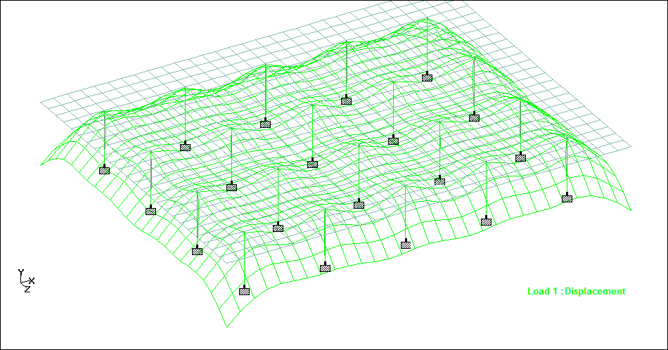
Here's an image of the analytical model.

Image

It’s a real model. Made out of string hanging from a wire frame. It makes one wonder why we bother with modern FEA other than to squeeze out incremental savings on materials. Which brings me onto the principle that calculation is not design, the role of calculation is to help verify design. Note the important word "help". That brings us neatly back to F1 and Newey's fabled drawing board. We're back on topic!

Now for some rapid fire examples....

Here's a temporary structure built when people didn't understand materials or analysis, so they had generous factors of ignorance. I found a 3d image, apparently it's all the rage in picture houses nowadays.

Image

Here's a permanent structure designed with all the power of modern computing and thorough non-destructive testing. Unfortunately one of the hangers failed when the bridge was empty due to crack propagation in the casting. This was despite thorough materials documentation in the supply chain.

Image

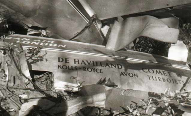
Talking of crack propagation, here's an embarrassing example:
Image

However good things come out of disasters when if we're humble enough to learn the lesson. The lesson from the Comet that led to this. Although we found out many years later that robustness was overlooked in one key area.

Image

Finally there's the spectre of fatigue mentioned by kilcoo316. Fatigue has no respect for FoS. I'll let kilcoo explain that one.


The lesson is that no matter how accurately we can analyse and test things there is always something unforeseen. That brings us onto the matter of robustness which is far more important in my mind than mere FoS. One could say FoS is a comfort rag for insecure engineers, those with the confidence to build focus on robustness every time. Unfortunately 114 people died in the Hyatt Regency collapse in Kansas in 1981 when robustness was overlooked. The calcs were probably immaculately laid out on the page and FoS careful applied.

Image

So for those skim reading....

Calculation is not design, the role of calculation is to help verify design


....


Oh, and I do love Nervi but I'm surprised you did not mention the Eladio Dieste. He used simple clay bricks made on site, none of that pretentious prefabricated post tensioning used by Nervi. .... and Dietse was South American. ;)

Image


* I usually do try to be inclusive of all cultures, but I left that word in place for the amusement of Americans. What word I hear you ask? Look again.

Smokes
Smokes
4
Joined: 30 Mar 2010, 17:47

Re: Safety Factors Used in Formula One

Post

Factor of safety is not just to do materials, it also has to do with risk of failure, i.e what happens if somthing does fail, will it be an enviromental catastrophe like the chernobyl power plant. How many people will get killed if a plane fell out of the sky. You can build something with a low FOS it will be a light structure but it will be expensive to maintain and run like and airplane or a F1 car, you may need to build sometime that operates in a harsh enviroment for 30 years with no downtime and maintenace these things tend to be big and heavy with a large corrsion allowance and have a very high initial investment cost.

User avatar
Ciro Pabón
106
Joined: 11 May 2005, 00:31

Re: Safety Factors Used in Formula One

Post

Lycoming, I do not know where your teacher got the design code you mention, but it is possible. Here you have the Irish one (very good) for masonry, first table contains safety factors for forces, second one (Table 4) for material resistance.

Because masonry is usually used in compression it has the same safety factors of other materials:
Image

Note that material resistance is rarely taken to the limit, bending is the limit (usually). The most important tool of a mason is the plumb.

Hi, forum masons!
Image

If you want to use masonry in areas with risk of earthquake (that is, the planet Earth, if you ask me) then you can avoid the problem of safety factors and use anchors.

Sections of masonry in Washington Monument anchored after damage by earthquake. Tunnels into the White House and Dick Cheney's office not depicted.
Image
Thanks, Richard, pretty nice explanation.

You mention dynamic relaxation. As I understand it, it is a method to do calculations, not a philosophy of design. It's a little cumbersome if you use it by hand, but it also allows you to calculate shells. It was one of the initial methods used to calculate them, do not be fooled by computer graphics: Gaudi, the Catalonian architect used it but he used real fabrics and weights hanging from them.

Dynamic relax
Image

I do not use it frequently because it is somewhat limited to cable and fabrics, so the size of the elements you mention (0.5 m) is a precondition of this method.

In bridges few elements can be treated solely in that way, we always have compression and bending moment.

Now, to answer the question, the factors of safety for plastic design should be:

For the material: 1

... if the material has well known properties, you test a part identical to the one you'll use and you use loads that represent well the load you will expect.

For the load: 1

... if the load is static or fluctuating, there are no shock loads and you use an accurate method to analyze the stress

For the geometry: 1

... if the manufacturing tolerances are tight and well held.

For the analysis: 1

... if the failure analysis you will use is derived from the state of stress, as in multiaxial static stress or fully reversed uniaxial fatigue stress.

For the reliability: 1

... if the reliability for the part is not high, for example 80% is required.

Hence, as Smokes points out (kind of) you can use a 1 "factor of safety" IF YOU COMPLY WITH THE ABOVE REQUIREMENTS. That is, you can use no safety factor to design the seat, the water tube (it always fails) the decals and the nose cone (people will break it anyway on the start).
Ciro

User avatar
Callum
6
Joined: 18 Jan 2009, 15:03
Location: Edinburgh, Scotland

Re: Safety Factors Used in Formula One

Post

Wow, there have been some fantastic and very interesting comments, thanks to all. It's nice to know there are some genuinely intelligent people here...

flyboy2160
flyboy2160
84
Joined: 25 Apr 2011, 17:05

Re: Safety Factors Used in Formula One

Post

richard_leeds wrote:...

Anyway, here's another old picture, this is the 60m span Mannheim gridshell...
richard, thanks for the mention of that very interesting structural concept. it reminds me of the lancaster bomber fuselage, the brainchild, i think, of the great barnes wallace:

Image

aral
aral
26
Joined: 03 Apr 2010, 22:49

Re: Safety Factors Used in Formula One

Post

flyboy2160 wrote:
richard_leeds wrote:...

Anyway, here's another old picture, this is the 60m span Mannheim gridshell...
richard, thanks for the mention of that very interesting structural concept. it reminds me of the lancaster bomber fuselage, the brainchild, i think, of the great barnes wallace:

http://i227.photobucket.com/albums/dd67 ... elage1.jpg
That was not the Lanc. It was the Wellington!

flyboy2160
flyboy2160
84
Joined: 25 Apr 2011, 17:05

Re: Safety Factors Used in Formula One

Post

gilgen wrote:....That was not the Lanc. It was the Wellington!
:lol: Thanks! I was going just by past reading memory, not an inet lookup - a sin nowadays. Ha! Did I get the Barnes Wallace part right? (Again just going by past reading memory...) He really was a very smart guy!

Greg Locock
Greg Locock
235
Joined: 30 Jun 2012, 00:48

Re: Safety Factors Used in Formula One

Post

Gaudi used the string method for the Sagrada Família, and there's a reasonable probability that it was used for gothic cathedrals as well.

There's a rather similar technique called membrane analsysis, where you take a rubber sheet, put a spare wheel in it (or other load), and then use the resulting shape for your steel for the spare wheel well. GM used that. It is rather an extravagant way of using up packaging volume, but it is a very economical use of steel.

We do use a factor of ignorance for fatigue - if we are designing for 50000 km of real world testing at the PG, the FEA target for durability might be 200000, ie a factor of 4 on cycles (not the actual numbers we use). That does NOT mean that everything is understressed by a factor of 4, as roughly, for steel construction as used in cars, a 10% reduction in stress doubles the life, in other words, in that example, the fatigue limited parts of the car would be generally 20% thicker than it needs to be. The reason that large FoI are used for fatigue is that the analysis method used is still rather iffy (best practice is iffy) given that the main thing we need to think about are spotwelds. Each spotweld is modeled with umpty elements, even so that isn't good enough.

Luckily, between the stiffness limited parts, and crash, and abuse strength tests such as bloody great potholes and kerbing, most of the car is overdesigned for fatigue anyway.

aral
aral
26
Joined: 03 Apr 2010, 22:49

Re: Safety Factors Used in Formula One

Post

flyboy2160 wrote:
gilgen wrote:....That was not the Lanc. It was the Wellington!
:lol: Thanks! I was going just by past reading memory, not an inet lookup - a sin nowadays. Ha! Did I get the Barnes Wallace part right? (Again just going by past reading memory...) He really was a very smart guy!
Yep, spot on. But oddly, have a look at the url quoted....this also says Lanc! So you are not the only one confused by WW11 bombers! Wasn't the form of construction referred to as "geodic"?

Richard
Richard
Moderator
Joined: 15 Apr 2009, 14:41
Location: UK

Re: Safety Factors Used in Formula One

Post

flyboy2160 wrote:richard, thanks for the mention of that very interesting structural concept. it reminds me of the bomber fuselage,
Aha, I'm glad you mentioned that because it is quite different. The bomber has a rigid geodetic* structure with fixed nodes. Actually looking at the node detailing I think it is more like a lamella shell. It acts like a rigid shell that happens to have holes. The nodes are firmly fixed in location and rotation.

The difference with the timber gridshells is that they deflect to distribute the forces, the square holes warp and slide so they are no longer square.

They are a highly visible way of explaining the force redistribution mentioned by Ciro. That's how we get rid of annoying FoS so we can focus on sexy slender slabs.

So this stress diagram ...

Image

Tells us that the slab is distributing forces like this ...

Image

We can use that knowledge of redistribution to develop structures that dynamically relax like this ...

Image

So what is happening in a concrete flat slab is identical to that floppy gridshell. The structure gets overloaded (typically at the support) but instead of exceeding the FoS and failing, the structure says "You silly numpty, what are you doing here? Go over to the midpsan, there's loads of spare capacity."

It's like the difference between a rigid beam axle on leaf springs compared to independent suspension with dampers. The springs are elastic while the dampers could be likened to plastic behaviour (if you squint on a foggy day).

* Thanks Greg - also you've not seen me on Friday night!

Greg Locock
Greg Locock
235
Joined: 30 Jun 2012, 00:48

Re: Safety Factors Used in Formula One

Post

geodetic. And wiki tells me that diagonal ribs were used in 18th century ships to brace the hulls (it wasn't a closed form trellis in that case, the skin of the hull was still stressed).

Nice thread chaps and chappesses (fat chance).