Energy storage theory.

Here are our CFD links and discussions about aerodynamics, suspension, driver safety and tyres. Please stick to F1 on this forum.
User avatar
Ciro Pabón
106
Joined: 11 May 2005, 00:31

Re: Energy storage theory.

Post

Please, take in account that I haven't seen drawings, but the explanantion I've read is a CVT with two disks, one for input (connected to the engine) and one for output (connected to the rotational or storage disk).

The input disk turns at the gearbox rpm speed. The output disk is coupled to the storage disk using a gear (let's say, with a 3:1 gear ratio) to increment the rpms of the storage disk.

The CVT works like this: the input and output disks are coupled by a viscous liquid. The closer the input and output disk are, the faster the output disk rotates. You have a mechanism to close the gap between input and output disks: the viscous liquid works like a clutch or an hydraulic automatic transmission.

Those rotational speeds you mention are nothing new. There are UPSs (Uninterrupted power supply) for computers based on flywheels that, from memory (we talked about them in the first KERS threads, a couple of years ago) reach 200,000 rpm since the 90's.

They are larger than the dimensions you mention. The storage disks are made of carbon fiber to withstand rotational forces at larger radii. The storage disk is within a cilinder that is able to contain the shards produced if the storage disk disintegrates.

Those units are used (like batteries) in computer rooms without any problem that I know. It could be argued that regular batteries are as dangerous as flywheels: what if a hydrogen-producing battery explodes and throws acid to the driver? :)

Actually, those flywheels are pretty clever: they don't use regular but magnetic bearings and the sleeve of the bearings works as a molecular air pump to keep the vacuum inside the storage disk. The magnetic bearings have circuitry that senses if the flywheel deviates from its axis and correct it in real time, and, if it senses that the flywheel is out of balance and it's going to break, stop the unit.

Pentadyne flywheel and magnetic levitating circuitry; they call units using steel disks "first generation flywheels" ;)
Image
Ciro

xpensive
xpensive
214
Joined: 22 Nov 2008, 18:06
Location: Somewhere in Scandinavia

Re: Energy storage theory.

Post

Thank you Ciro, this certainly explains a few things on the transmission to and from the enery-storage flywheel.

A crusial factor however, is of course the power-loss of the viscous-coupling. Having worked with similar arrangements within the area speed-control in the past, I know that it can be rather power consuming if the spped differential is high.

Simply explained, if the output speed is half of the input speed, efficiency is only 50%, when the Torque will be the same on in and out, remember Power = Torque*angular speed.
"I spent most of my money on wine and women...I wasted the rest"

User avatar
machin
162
Joined: 25 Nov 2008, 14:45

Re: Energy storage theory.

Post

I'd be surprised if a fluid clucth was used... as you say the efficiencies just aren't there..... Bearing in mind that the engine is already turning at 19,000 rpm its not a big ratio to get to 65,000 rpm -so as long as the KERS is connected at the right end of the gearbox it shouldn't be a big problem I guess....
COMPETITION CAR ENGINEERING -Home of VIRTUAL STOPWATCH

User avatar
ackzsel
0
Joined: 15 Nov 2005, 15:40
Location: Alkmaar, NED

Re: Energy storage theory.

Post

How about not only using the energy released from braking but also letting the engine help the flywheel/generator+battery to load? I don't know how much is possible with KERS being controlled by SECU but I think it would really add a lot of energy to the storage system if the engine could help when it's not needed.

User avatar
Ciro Pabón
106
Joined: 11 May 2005, 00:31

Re: Energy storage theory.

Post

machin wrote:I'd be surprised if a fluid clucth was used... as you say the efficiencies just aren't there.....
Well, I went into Torotrak site, to prove you wrong, because that's what I read (I repeat, read) at Autosport. However, machin is right (altough, curiously, Autosport is right too). Read on if you want to know why:
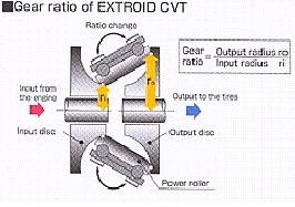
The components within each variator include an input disc and an opposing output disc. Each disc is formed so that the gap created between the discs is "doughnut" shaped; that is, the toroidal surfaces on each disc form the toroidal cavity.

Two or three rollers are located inside each toroidal cavity and are positioned so that the outer edge of each roller is in contact with the toroidal surfaces of the input disc and output disc. As the input disc rotates, power is transferred via the rollers to the output disc, which rotates in the opposite direction to the input disc.

The angle of the roller determines the ratio of the variator, and therefore a change in the angle of the roller results in a change in the ratio. So, with the roller at a small radius (near the center) on the input disc and at a large radius (near the edge) on the output disc, the variator produces a "low" ratio.

Moving the roller across the discs to a large radius at the input disc and corresponding low radius at the output produces the "high" ratio, and provides the full ratio sweep in a smooth, continuous manner.

The transfer of power through the contacting surfaces of the discs and rollers takes place via a microscopic film of specially developed long-molecule traction fluid. This fluid separates the rolling surfaces of the discs and rollers at their contact points.

The input and output discs are clamped together within each variator unit. The traction fluid in the contact points between the discs and rollers become highly viscous under this clamping pressure, increasing its "stickiness" and creating an efficient mechanism for transferring power between the rotating discs and rollers.
I guess I misunderstood the guys at Autosport when they claimed that the viscous fluid was the only mean of transferring power: actually, it is, but it's not the way to change the CVT ratio, as machin intuitively understood. Thanks, pal. However, I still think (from the previous description) that the fluid offers some kind of clutch, because it (probably) allows some slippage between input and output, depending on the "clamping pressure".

I would be very grateful to anyone who can post a drawing (worth a thousand words or, in my case, more like two or three thousand... :)).
ackzsel wrote:How about not only using the energy released from braking but also letting the engine help the flywheel/generator+battery to load?
As we said, it's forbidden by regulations. Sad: it would allow for a lot of efficiency, like the diesel-electric locomotives do. Besides, electric motors have a lot of torque, as discussed here.

A perfect solution would be something like a micro-turbine charging some energy storage system and an electric motor moving the wheels. Unfortunately, enough energy density for that kind of storage doesn't exist yet (that I know).

Fantasy, you say? No, I say: fantastic, but no fantasy. ;)
Ciro

User avatar
machin
162
Joined: 25 Nov 2008, 14:45

Re: Energy storage theory.

Post

The transfer of power through the contacting surfaces of the discs and rollers takes place via a microscopic film of specially developed long-molecule traction fluid
... this is basically the same as any "metal to metal" contact within a properly engineered machine... if everything is lubricated properly there is actually NO metal to metal contact at all.... the metal parts are held apart by a microscopic film of oil... so all those gears aren't actually touching eachother.. until something goes wrong...
COMPETITION CAR ENGINEERING -Home of VIRTUAL STOPWATCH

User avatar
machin
162
Joined: 25 Nov 2008, 14:45

Re: Energy storage theory.

Post

Good diagram showing Toroidal CVT:-

Image
COMPETITION CAR ENGINEERING -Home of VIRTUAL STOPWATCH

pipex
pipex
6
Joined: 31 Jul 2008, 09:27
Location: The net

Re: Energy storage theory.

Post

Nice information about the flywheels Ciro, Thanks :)
"We will have to wait and see".

xpensive
xpensive
214
Joined: 22 Nov 2008, 18:06
Location: Somewhere in Scandinavia

Re: Energy storage theory.

Post

Just a few observations, as for Toyota's claim of an energy-storage of 400 kJ giving 80 Hp for 6.8s, that is not an estimation, rather very simple physics.
400 kJ is the same energy amount as 400Ws, equally spent over 6.8s (400 000 over 6.8) equals 58.8 kW or 80 Hp. But that's in a perfect world, after that you have the issue of efficiency ratio between the storage and the rear wheels.

Ciro wrote earlier:
The CVT works like this: the input and output disks are coupled by a viscous liquid. The closer the input and output disk are, the faster the output disk rotates. You have a mechanism to close the gap between input and output disks: the viscous liquid works like a clutch or an hydraulic automatic transmission.
I am happy that this was cleared up, when such a way of regulating the output speed is most inefficient, which is also down to simple laws of physics.
Before the age of frequency converters, this method was sometimes used as a simple way to control the rotational speed of pumps and fans in industry.
But again, as input and output torque will be the same, efficiency is directly proportional to the difference in Rpm.

Thanks for the pic of the Toroidal CVT, machine, in a way a variable planetary-gear.
"I spent most of my money on wine and women...I wasted the rest"