2014-2020 Formula One 1.6l V6 turbo engine formula

All that has to do with the power train, gearbox, clutch, fuels and lubricants, etc. Generally the mechanical side of Formula One.
Tommy Cookers
Tommy Cookers
643
Joined: 17 Feb 2012, 16:55

Re: Formula One 1.6l V6 turbo engine formula

Post

wuzak wrote:A diagram showing the Rolls-Royce Crecy 2 stroke sleeve valve turbocompound engine.

Not sure how much power the turbine gave, but the Crecy had a lot of exhaust energy.

The Allison V-1710-127 (-E27) also had a single stage axial turbine. The base engine was 2000-2200hp, the turbocompound was 2900-3000hp. About 50% power improvement!
IIRC the Crecy had a lot of exhaust massflow but the exhaust was not particularly energetic
there being a large surplus of air going through the engine

the compounded Allison was made to use specially high grade Triptane-based fuel eg 200 PN
to give higher power via specially high mep, via 108" Hg induction pressure, (the CR being left as standard for this purpose)
ie your 50% (really 40%) improvement in max power was mostly due to the fuel, and mostly piston-to-crankshaft not compound
the same fuel allowed raised CR on the base engine, improving both power and efficiency
(this fuel was never used in service)
RETRO EDIT (for self)
the above paragraph is wrong re Triptane
wuzaks post at 1126 this day is correct re the genesis of the Allison compound
thanks for that, w


all these WW2 era aircraft engines had low CR ie 6:1-7:1 (sub-optimal in cruise) to allow temporary very high mep and power
(the Wright TC that was used in the real world gave 6% gain in cruise and 17% at takeoff power)
Wright stated that the TC benefit was to crankshaft power at low altitude and speed (the TC was for US Navy patrol aircraft)
ie that at high altitude and speed an engine would naturally convert exhaust energy into jet thrust without the TC
(so the base Allison and others would have more propulsion power in use than your testbench power would suggest)

they all had much more energetic exhaust than the 2014 F1, which will have one job to do, and about a 12:1 CR for that job
the TC recovery in these engines will be about 10%
Last edited by Tommy Cookers on 03 Mar 2013, 11:05, edited 2 times in total.

User avatar
pgfpro
75
Joined: 26 Dec 2011, 23:11
Location: Coeur d' Alene ID

Re: Formula One 1.6l V6 turbo engine formula

Post

WhiteBlue wrote:
matt21 wrote:
wuzak wrote:The idea of the twin scroll turbo is that there aren't two exhaust streams overlapping at the same time - which can cause loss of scavenging.
I´m aware of this.
You´re right that the mass flow is the same, but the volumetric flow is different.
So if you get all the exhaust gases in one scroll you can achieve a higher exhaust gas velocity which in effect gives you a higher momentum.

Second idea:
Is a bypass of the intercooler allowed? I canot find anything in the rules.
Back in the 80ies Honda had this in order to achieve better throttle response.
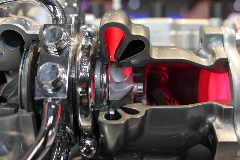
The twin scroll has only advantages however you look at it. A single scroll would have to distribute one mass flow 360° around the turbine entry with a fairly long path. The twin scrolls have only to cover 180°. So they can be shorter. The exhaust pipes also can be shorter for the engine with exhaust ports on the outside of the V. And it makes for a more compact packaging of the exhaust routes as well. So however you look at it twin scroll has only advantages unless you look at the fabricating costs which are slightly higher. But that has no priority for an F1 project if you can gain some power and better packaging. So I'm fairly sure that all manufacturers will design twin scroll turbine entries.
A twin scroll can be just one inlet that's divided. This is the most used type today.
Example:Image

WB I see what your saying IMHO as a bad design. I want the exhaust to be attach between each turbine blade as long as possible. This gives it enough time to pull the energy out of the exhaust gas (thermal and mass flow). To fast and your wasting useful exhaust gas energy. As the exhaust gas is carried from inducer to the exducer @ almost 360* it will have a nice pressure drop. This will result in a higher pressure gradient then if dump at 180* or less. If we dump the exhaust gas off the turbine wheel to soon we will produce a higher post turbine pressure. Not good.

The mono turbo is what I would call a dual inlet twin scroll hybrid. Because of its duel entry you will have less then 180* of exhaust to be attach between each turbine blade. So now you have to dump the exhaust off the turbine wheel faster. The mono turbo pictures even show the turbine wheel design to make this happen.

Now the kicker. I think what you see in the Renault turbo picture is a twin scroll turbo. Look closely at the turbine housing. They don't show us the down pipe. :?: I wonder why.
Last edited by pgfpro on 01 Mar 2013, 23:31, edited 1 time in total.
building the perfect beast

User avatar
WhiteBlue
92
Joined: 14 Apr 2008, 20:58
Location: WhiteBlue Country

Re: Formula One 1.6l V6 turbo engine formula

Post

pgfpro wrote:
WhiteBlue wrote:
matt21 wrote:I´m aware of this.
You´re right that the mass flow is the same, but the volumetric flow is different.
So if you get all the exhaust gases in one scroll you can achieve a higher exhaust gas velocity which in effect gives you a higher momentum.

Second idea:
Is a bypass of the intercooler allowed? I canot find anything in the rules.
Back in the 80ies Honda had this in order to achieve better throttle response.
The twin scroll has only advantages however you look at it. A single scroll would have to distribute one mass flow 360° around the turbine entry with a fairly long path. The twin scrolls have only to cover 180°. So they can be shorter. The exhaust pipes also can be shorter for the engine with exhaust ports on the outside of the V. And it makes for a more compact packaging of the exhaust routes as well. So however you look at it twin scroll has only advantages unless you look at the fabricating costs which are slightly higher. But that has no priority for an F1 project if you can gain some power and better packaging. So I'm fairly sure that all manufacturers will design twin scroll turbine entries.
A twin scroll can be just one inlet that's divided. This is the most used type today.
Example:http://i147.photobucket.com/albums/r312 ... a79436.jpg

WB I see what your saying IMHO as a bad design. I want the exhaust to be attach between each turbine blade as long as possible. This gives it enough time to pull the energy out of the exhaust gas (thermal and mass flow). To fast and your wasting useful exhaust gas energy. As the exhaust gas is carried from inducer to the exducer @ almost 360* it will have a nice pressure drop. This will result in a higher pressure gradient then if dump at 180* or less. If we dump the exhaust gas off the turbine wheel to soon we will produce a higher post turbine pressure. Not good.

The mono turbo is what I would call a dual inlet twin scroll hybrid. Because of its duel entry you will have less then 180* of exhaust to be attach between each turbine blade. So now you have to dump the exhaust off the turbine wheel faster. The pictures even show the turbine wheel design to make this happen.

Now the kicker. I think what you see in the Renault turbo picture is a twin scroll turbo. Look closely at the turbine housing. They don't show us the down pipe. :?: I wonder why.
Your picture shows nothing how this particular turbine intake is designed. All we see is that there is some overlap. So it is not 180°. But that does not change much of the disputed conditions. And your reasoning is still invalid if you design feed angle of the scroll in another way. The turbine will always get the same mass feed. When it is fed by two scrolls you will always have the shortest flow pathes in the tubes and in the intake. That will also give you the best power and the least cross influence between the V banks of cylinders.
Formula One's fundamental ethos is about success coming to those with the most ingenious engineering and best .............................. organization, not to those with the biggest budget. (Dave Richards)

User avatar
pgfpro
75
Joined: 26 Dec 2011, 23:11
Location: Coeur d' Alene ID

Re: Formula One 1.6l V6 turbo engine formula

Post

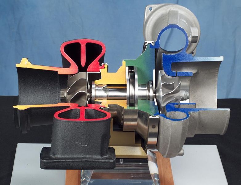
Your picture shows nothing how this particular turbine intake is designed. All we see is that there is some overlap. So it is not 180°. But that does not change much of the disputed conditions. And your reasoning is still invalid if you design feed angle of the scroll in another way. The turbine will always get the same mass feed. When it is fed by two scrolls you will always have the shortest flow pathes in the tubes and in the intake. That will also give you the best power and the least cross influence between the V banks of cylinders.
Another pic in a single inlet twin scroll turbo cut away.
This pic shows the inlet better.
Image
building the perfect beast

wuzak
wuzak
467
Joined: 30 Aug 2011, 03:26

Re: Formula One 1.6l V6 turbo engine formula

Post

Tommy Cookers wrote:IIRC the Crecy had a lot of exhaust massflow but the exhaust was not particularly energetic
there being a large surplus of air going through the engine
Exhaust thrust was equivalent to 30% of the engine's power. There was a lot of air pumped through the engine, and it required a lot of power to drive the compressor. The turbine recovered that power and then some.

Tommy Cookers wrote:the compounded Allison was made to use specially high grade Triptane-based fuel eg 200 PN
to give higher power via specially high mep, via 108" Hg induction pressure, (the CR being left as standard for this purpose)
ie your 50% (really 40%) improvement in max power was mostly due to the fuel, and mostly piston-to-crankshaft not compound the same fuel allowed raised CR on the base engine, improving both power and efficiency
(this fuel was never used in service)
No, the turbo compound Allison only ran on standard PN130 or PN150 grade fuel. The base engine could achieve 2000hp on PN150 fuel with ADI (water injection), with later variants taking this up to 2200hp.

The CR on the turbocompound remained at 6:1 as it allowed more boost and higher power. Earlier V-1710s used 6.65:1 and the V-3420, basically two joined V-1710s, had a CR of 8.5:1, being for use with long range bombers.

A non-compound Allison was tested to 3000hp using triptane based fuel. This was a different engine and program to the E27 turbo compound.

Tommy Cookers wrote:all these WW2 era aircraft engines had low CR ie 6:1-7:1 (sub-optimal in cruise) to allow temporary very high mep and power (the Wright TC that was used in the real world gave 6% gain in cruise and 17% at takeoff power)
Wright stated that the TC benefit was to crankshaft power at low altitude and speed (the TC was for US Navy patrol aircraft)
ie that at high altitude and speed an engine would naturally convert exhaust energy into jet thrust without the TC
(so the base Allison and others would have more propulsion power in use than your testbench power would suggest)
Daimler-Benz engines had higher compression ratios - DB 601s had CRs of just under 9. The Napier Sabre had 7:1. The Merlin and Griffon used 6:1, and some Allison V-1710s.

wuzak
wuzak
467
Joined: 30 Aug 2011, 03:26

Re: Formula One 1.6l V6 turbo engine formula

Post

pgfpro wrote:
Your picture shows nothing how this particular turbine intake is designed. All we see is that there is some overlap. So it is not 180°. But that does not change much of the disputed conditions. And your reasoning is still invalid if you design feed angle of the scroll in another way. The turbine will always get the same mass feed. When it is fed by two scrolls you will always have the shortest flow pathes in the tubes and in the intake. That will also give you the best power and the least cross influence between the V banks of cylinders.
Another pic in a single inlet twin scroll turbo cut away.
This pic shows the inlet better.
http://i147.photobucket.com/albums/r312 ... 27b93a.jpg
Doesn't show whether the flange has one hole or it is divided to the flange at which two separate exhaust are connected.

User avatar
pgfpro
75
Joined: 26 Dec 2011, 23:11
Location: Coeur d' Alene ID

Re: Formula One 1.6l V6 turbo engine formula

Post

wuzak wrote:
pgfpro wrote:
Your picture shows nothing how this particular turbine intake is designed. All we see is that there is some overlap. So it is not 180°. But that does not change much of the disputed conditions. And your reasoning is still invalid if you design feed angle of the scroll in another way. The turbine will always get the same mass feed. When it is fed by two scrolls you will always have the shortest flow pathes in the tubes and in the intake. That will also give you the best power and the least cross influence between the V banks of cylinders.
Another pic in a single inlet twin scroll turbo cut away.
This pic shows the inlet better.
http://i147.photobucket.com/albums/r312 ... 27b93a.jpg
Doesn't show whether the flange has one hole or it is divided to the flange at which two separate exhaust are connected.
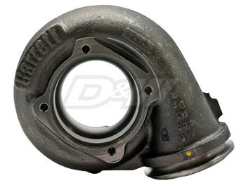
It's just a normal everyday T3 or T4 divided inlet flange. The exhaust manifold would also have the same type of divided flange. The collector would be designed in a fashion that would keep exhaust pluses from interfering with each other.
building the perfect beast

wuzak
wuzak
467
Joined: 30 Aug 2011, 03:26

Re: Formula One 1.6l V6 turbo engine formula

Post

autogyro wrote:Nice to see the RR Crecy again Wuzak.
Makes you think that perhaps they have cottoned on to using the turbo outlet for thrust.
The Crecy gave a huge amount of its performance from exhaust thrust.
I dont think the coander effect will be enough to redirect the exhaust for downforce under braking though.
It is a big angle from the regs.
Should keep Adrian, Rory and the others busy until 2014.
I think they will direct the exhaust to the beam wing and then try to get that to influence teh diffuser and/or rear wing.

wuzak
wuzak
467
Joined: 30 Aug 2011, 03:26

Re: Formula One 1.6l V6 turbo engine formula

Post

pgfpro wrote:It's just a normal everyday T3 or T4 divided inlet flange. The exhaust manifold would also have the same type of divided flange. The collector would be designed in a fashion that would keep exhaust pluses from interfering with each other.
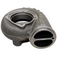
So, much like the "mono turbo", only with the two entries together.

That is what the turbo on the Mercedes-Benz looks like. It idn't what the turbo in the Ranult picture looks like.

autogyro
autogyro
53
Joined: 04 Oct 2009, 15:03

Re: Formula One 1.6l V6 turbo engine formula

Post

Anybody got any exhaust gas flow diagrams for a turbocharger.
I cant see why the flow has to go 360 degrees to extract all the energy.
The shape of the blades will deflect the gas to outlet long before that IMO.

User avatar
pgfpro
75
Joined: 26 Dec 2011, 23:11
Location: Coeur d' Alene ID

Re: Formula One 1.6l V6 turbo engine formula

Post

wuzak wrote:
pgfpro wrote:It's just a normal everyday T3 or T4 divided inlet flange. The exhaust manifold would also have the same type of divided flange. The collector would be designed in a fashion that would keep exhaust pluses from interfering with each other.
So, much like the "mono turbo", only with the two entries together.

That is what the turbo on the Mercedes-Benz looks like. It idn't what the turbo in the Ranult picture looks like.
Yes sir.

Here's a better picture of a divided twin scroll that looks more like the Renault turbo picture.

Image
Image
building the perfect beast

rjsa
rjsa
51
Joined: 02 Mar 2007, 03:01

Re: Formula One 1.6l V6 turbo engine formula

Post

Image
http://www.modified.com/tech/modp-0906- ... ewall.html

Failed to see where it was defined that a twin scroll turbine needs to have more than one exhaust intake. Much to the contrary, work is done at length to assure equal length paths from every cylinder to the intake.

Image

User avatar
pgfpro
75
Joined: 26 Dec 2011, 23:11
Location: Coeur d' Alene ID

Re: Formula One 1.6l V6 turbo engine formula

Post

rjsa wrote:http://image.modified.com/f/tech/modp-0 ... t_away.jpg
http://www.modified.com/tech/modp-0906- ... ewall.html

Failed to see where it was defined that a twin scroll turbine needs to have more than one exhaust intake. Much to the contrary, work is done at length to assure equal length paths from every cylinder to the intake.

http://image.modified.com/f/tech/modp-0 ... nifold.jpg
Thanks for the pic. That's one of the pictures I was looking for and couldn't find? lol
building the perfect beast

wuzak
wuzak
467
Joined: 30 Aug 2011, 03:26

Re: Formula One 1.6l V6 turbo engine formula

Post

rjsa wrote:http://image.modified.com/f/tech/modp-0 ... t_away.jpg
http://www.modified.com/tech/modp-0906- ... ewall.html

Failed to see where it was defined that a twin scroll turbine needs to have more than one exhaust intake. Much to the contrary, work is done at length to assure equal length paths from every cylinder to the intake.

http://image.modified.com/f/tech/modp-0 ... nifold.jpg
The problem is that some engine formats will have overlap between exaust events for two or more cylinders. By seprating the exhaust flows into two and using a twin scroll turbo you can avoid this and get better results.

And equal length exhausts only work at certain engine speeds.
Last edited by wuzak on 03 Mar 2013, 01:32, edited 1 time in total.

rjsa
rjsa
51
Joined: 02 Mar 2007, 03:01

Re: Formula One 1.6l V6 turbo engine formula

Post

Ok, I got that, but nothing says two separate entries at different phases in the turbine cycle, right? Because I was being led to believe that it was the only way to do it a few pages back.