The formula given in the previous page uses theta, not phi.
The derivative of the sine is the cosine.
The scale for Chris's graphic is on the left. It's in mm/s2 (curious units) and the numbers go from -1250 mm/s2 to +750 mm/s2.
(very low, roughly a tenth of a G: why? What kind of engine is that, Chris? A Wartsila at 75 rpm? What am I missing here?).
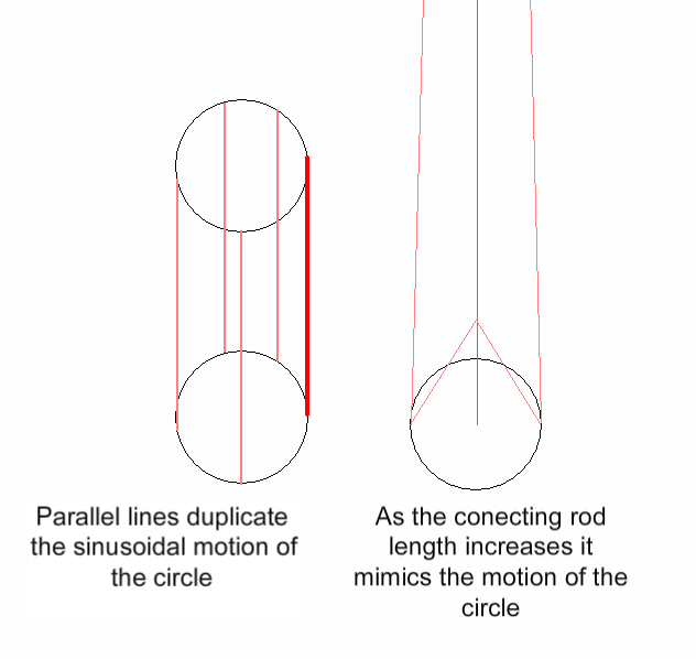
I'm afraid it's so long ago I can't really remember. Looking back on it, it's a bit of a crap graph really. But it does show that as rod length to stroke ratio affects peak forces, and affects the shape of the acceleration curve.
That particular graph isn't of any real engine, it used arbritrary values to test if a model worked. I did so many similar things back than, that this could either be an engine that is rotating slowly or I labelled the graph wrong. If the scale were m/s^2 it would give peak figures of 125g and 75g which are more sensible.
With the figures quoted, i'd guess I messed up the axis units.
I did make and and post it whilst I was drunk!


