Innovo 2012 F1 Car - Tozza Mazza and JordanGP

Post here information about your own engineering projects, including but not limited to building your own car or designing a virtual car through CAD.
User avatar
Tozza Mazza
1
Joined: 13 Jan 2011, 12:00
Location: UK

Re: Innovo 2012 F1 Car

Post

wesley123 wrote:I personally am in the opinion you should add at least a piece of floor in front of it, for example make the floor really short with the floor's splitter, I think by that way you get an idea and decent results of how your floor will work and it's interaction with the wing. An diffuser does barely anything without the floor properly simulated and the floor attached to it.

Also it is great to say you want to learn! Being quite similair here I came to the forum in 08 barely knowing anything about aerodynamics, now 3 years later I know I have learned a lot, too bad I could not apply this to my study since I do not meet the requirements to do such an study. I really hope you will be able to do the study, and maybe in 10 years or so we have a new Newey on the grid.
Thanks, I've whipped up a basic floor, and we're going to run an analysis, using the ground also, should give the initial result we wanted :)

wesley123
wesley123
204
Joined: 23 Feb 2008, 17:55

Re: Innovo 2012 F1 Car

Post

Do not forget the rake you plan to run! Forgot that in my post lol
"Bite my shiny metal ass" - Bender

User avatar
Tozza Mazza
1
Joined: 13 Jan 2011, 12:00
Location: UK

Re: Innovo 2012 F1 Car

Post

wesley123 wrote:Do not forget the rake you plan to run! Forgot that in my post lol
Gonna keep it flat on the first analysis, then maybe try couple of degrees on the next one. Should increase diffuser efficiency due to higher pressure difference, but it will lose out a bit on the ground effect. Wing's will also get a higher AoA, so we will see more drag, in theory, if we run more AoA.

Will be an interesting analysis when we run it.

User avatar
ringo
230
Joined: 29 Mar 2009, 10:57

Re: Innovo 2012 F1 Car

Post

Tozza there is a very critical thing that you are leaving out.

You need to create a track surface. The aero will look weird because you have a car floating in mid air.
There needs to be a ground to get ground effect.

The floor can be a rectangular block. Create it as a separate part, then make an assembly then import the block into the assembly.
Make about 5 cm of ground clearance to begin with and then you are good to go.

Oh yeah, increase your floor length. The diffuser will behave more realistically if you have at least 1.5 meters of floor attached to it.
For Sure!!

User avatar
Tozza Mazza
1
Joined: 13 Jan 2011, 12:00
Location: UK

Re: Innovo 2012 F1 Car

Post

ringo wrote:Tozza there is a very critical thing that you are leaving out.

You need to create a track surface. The aero will look weird because you have a car floating in mid air.
There needs to be a ground to get ground effect.

The floor can be a rectangular block. Create it as a separate part, then make an assembly then import the block into the assembly.
Make about 5 cm of ground clearance to begin with and then you are good to go.
We have it :D

It was left out for the wing, as they were just 'test' analysis' as we weren't sure if our CAD formats being exchanged was working, and were just trying out the analysis.

It's all systems go on development at the moment. A very basic, yet hopefully effective front wing is reaching the end of initial design. This design is much better than the last, due to its massive scope for developement.

The Survival cell and nose have been changed majorly since before, taking major influences from the RB7 (especially with the aerodynamically shaped fuel tank, which we lacked before), allowing our relatively short (3300mm) wheelbase to just fit.

I have done a couple of drawings of sidepods (Red Bull style), but still remain intrigued by the Toro Rosso Double Floor design, does anyone know which design works best for the car as a whole. (U pods are too ugly for me, and have little room for developement).

The simplification of our design will hopefully help us in our ability to develop the car, using the available CFD.

I'd post pics but it's got big gaps so looks too weird.

P.S Ringo, if you could post a pic of just your fuel tank, it'd be really great, I'm just so confused as to what the top of it behind the cockpit entry template looks like, I've made loads of drawings and looked at pictures, and they never seem to match! :?

User avatar
ringo
230
Joined: 29 Mar 2009, 10:57

Re: Innovo 2012 F1 Car

Post

here is a hint:
Image
The tank is everything bellow the roll hoop.
I used this as a guide.

But mine was a little difficult to align with the engine cover and tub. Mimicing the rebull will be even harder as well if you are strictly making the tank big enough to do a race distance, while having a short wheel base.
The tank has to be T shaped at the base as well to sit on the floor.
For Sure!!

User avatar
Tozza Mazza
1
Joined: 13 Jan 2011, 12:00
Location: UK

Re: Innovo 2012 F1 Car

Post

Image

This is our fuel tank, it's close, I know that much, to what is considered conventional, as I said, there are no images of the top bit, and my drawings and pictures of real cars, never match no matter how many times I ammend them.

(ignore the hole, its not finished, I'm hesitant to continue when I am doubting its correct - ness)

EDIT: Also ignore the step, it will have the 2 25mm radii, when finished.

User avatar
ringo
230
Joined: 29 Mar 2009, 10:57

Re: Innovo 2012 F1 Car

Post

It looks correct. It may petrude into the side pod space a bit depending on how you shift the volume, but it looks pretty much like what i have.
The top of mine is just shaped to the exact contour of the outer skin.

It was a PITA though to get it matching smoothly with the sidepods and engine cover.
You will find the cockpit makes it difficult to get a nice taper in the side view.

Studying the shoulder of the toyota could give a sound solution.
For Sure!!

User avatar
Tozza Mazza
1
Joined: 13 Jan 2011, 12:00
Location: UK

Re: Innovo 2012 F1 Car

Post

ringo wrote:It looks correct. It may petrude into the side pod space a bit depending on how you shift the volume, but it looks pretty much like what i have.
The top of mine is just shaped to the exact contour of the outer skin.

It was a PITA though to get it matching smoothly with the sidepods and engine cover.
You will find the cockpit makes it difficult to get a nice taper in the side view.

Studying the shoulder of the toyota could give a sound solution.
Is the top, semi circular section, similar to yours, this is the bit I struggled with most, as all my pictures were contradicting, and I got all confused?

If it is, Then I'll just finish the design off!

There are next to no pictures of F1 fuel tanks on the internet (especially 2010-2011 designs!)

User avatar
Tozza Mazza
1
Joined: 13 Jan 2011, 12:00
Location: UK

Re: Innovo 2012 F1 Car

Post

As an idea, could brake callipers be placed at the bottom of the brake drum, to lower CofG just a tiny amount?

Could be worth a few thousandths a lap :lol:

Is this practical, or even possible?

User avatar
ringo
230
Joined: 29 Mar 2009, 10:57

Re: Innovo 2012 F1 Car

Post

Tozza Mazza wrote:
ringo wrote:It looks correct. It may petrude into the side pod space a bit depending on how you shift the volume, but it looks pretty much like what i have.
The top of mine is just shaped to the exact contour of the outer skin.

It was a PITA though to get it matching smoothly with the sidepods and engine cover.
You will find the cockpit makes it difficult to get a nice taper in the side view.

Studying the shoulder of the toyota could give a sound solution.
Is the top, semi circular section, similar to yours, this is the bit I struggled with most, as all my pictures were contradicting, and I got all confused?

If it is, Then I'll just finish the design off!

There are next to no pictures of F1 fuel tanks on the internet (especially 2010-2011 designs!)
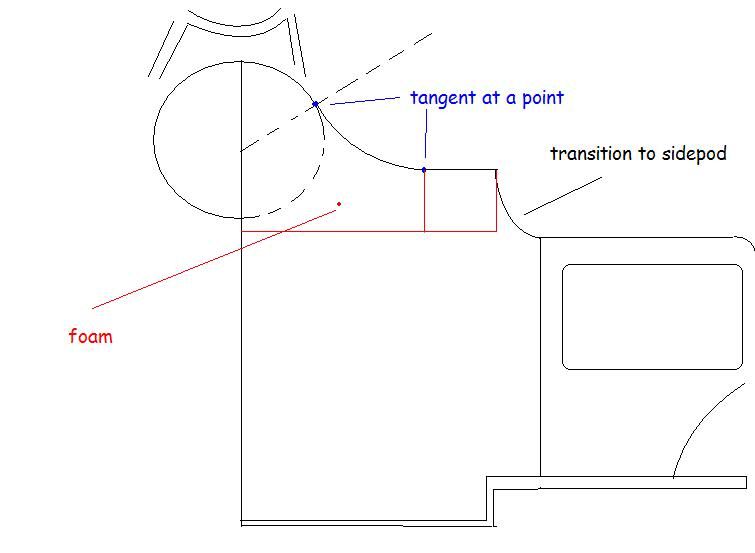
You should widen the top semi circular bit a little and make it tangential to the flat shoulder.
Image

I may have to roll back my model so you can see the shape.
For Sure!!

User avatar
Tozza Mazza
1
Joined: 13 Jan 2011, 12:00
Location: UK

Re: Innovo 2012 F1 Car

Post

ringo wrote:
Tozza Mazza wrote:
ringo wrote:It looks correct. It may petrude into the side pod space a bit depending on how you shift the volume, but it looks pretty much like what i have.
The top of mine is just shaped to the exact contour of the outer skin.

It was a PITA though to get it matching smoothly with the sidepods and engine cover.
You will find the cockpit makes it difficult to get a nice taper in the side view.

Studying the shoulder of the toyota could give a sound solution.
Is the top, semi circular section, similar to yours, this is the bit I struggled with most, as all my pictures were contradicting, and I got all confused?

If it is, Then I'll just finish the design off!

There are next to no pictures of F1 fuel tanks on the internet (especially 2010-2011 designs!)
You should widen the top semi circular bit a little and make it tangential to the flat shoulder.
Image

I may have to roll back my model so you can see the shape.
So does the semi circle section shrink into the flat section, like in my current design?

Sorry about the many questions, this is the only confusing part of the whole car, the rest, bar the sidepod design (which is many, many drawings so far, and I have no CAD yet!).

Tom.

User avatar
ringo
230
Joined: 29 Mar 2009, 10:57

Re: Innovo 2012 F1 Car

Post

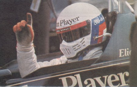
Here is front view.
Image

The circle needs to have big radius, as you can see from the ferrari shot.
Draw something like this in a plane. Draw something similar at the face of the engin then loft it.

A easier approach to this is to make the whole body of the car one piece, which is carved down.

I found out that doing the car piece by piece is more difficult.
For Sure!!

User avatar
Tozza Mazza
1
Joined: 13 Jan 2011, 12:00
Location: UK

Re: Innovo 2012 F1 Car

Post

So the circle section of the tank is still there by the engine, or is it flat at the front of the engine?

:?

I am so sorry for dragging this out!

The whole tank is being designed around the shape of the sidepods, so the car is being designed as one piece, just split into section.

In the survival cell area there are 4 main sections, bulkheads, splitter, cockpit and fuel tank, but the design of these is obviously influenced by the sidepods, engine cover, floor and nose cone.

Thinking of the car as a whole, and not of seperate sections does wonders for the design.

User avatar
ringo
230
Joined: 29 Mar 2009, 10:57

Re: Innovo 2012 F1 Car

Post

Tozza Mazza wrote:So the circle section of the tank is still there by the engine, or is it flat at the front of the engine?
depends on the shape of your car. You could keep it there, but smaller radius.
Or to make life easier just do the body as one piece, with the knowledge that the tank can fit in the body.

:?

The whole tank is being designed around the shape of the sidepods, so the car is being designed as one piece, just split into section.

In the survival cell area there are 4 main sections, bulkheads, splitter, cockpit and fuel tank, but the design of these is obviously influenced by the sidepods, engine cover, floor and nose cone.

Thinking of the car as a whole, and not of seperate sections does wonders for the design.
Yeah then you are good to go. Best to draw your geometry before trying to make it work on the CAD.

Mine is multi bodied, but it takes too much effort to do it this way, hence my slow update rate.
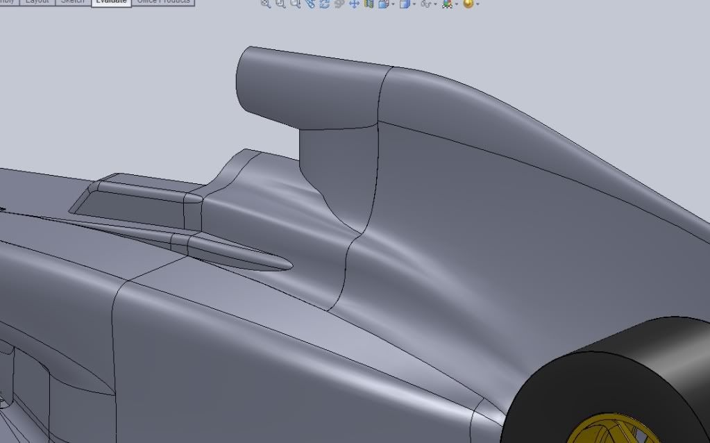
Here you see that i have a profile in a plane ahead of the engine. This is lofted to the plane at the rear of the entry template.
Image

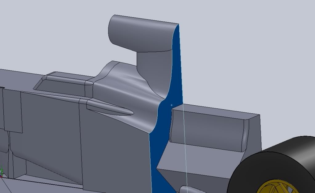
removing sidepod and engine cover....
Image
Be careful with these curves as they determine how good the car looks. Many 3d models tend to have a weird looking gas tank area, especially where the sidepods slope down and taper inward.

Note however that the air intake is not a part of the tank profile. I did the tank first, with a similar look to yours, then built, extruded, the air intake on top of it into the same body.
For Sure!!