Fiberglass composite study in SolidWorks, Help !

Post here information about your own engineering projects, including but not limited to building your own car or designing a virtual car through CAD.
firasf1dream
firasf1dream
4
Joined: 18 Apr 2014, 21:26

Fiberglass composite study in SolidWorks, Help !

Post

hello guys,
i hope you all having a good day :)
well i need some help in a study of composite parts, to be specific Fiberglass composite in SolidWorks Simulation, i made many research and found the properties for E-Glass, i will be building my part with Chopped Strand Mat from Owen Corning, E-Glass below the information i got on the packages:
- Fibre:
Chopped Strand Mat Emulsion
Product: 300G/M2-125CM
Type: E-Glass
Batch No: LCL/JA/126
Gross Weight: 48 KGs
Net Weight: 46 KGs

Explanation:
Weight: 300g/m2
Width: 125 cm

- Resine:
Resin Crystic 125 PA (CS)
R2030740225
(PRE ACCELERATED)
Batch No: 3187524
Net Weight: 225KGs
Manufactured: 02.09.2014

So I need help please on how to work with Chopped Strand Mat in solidworks how to study the part using this material ?

sgth0mas
sgth0mas
3
Joined: 18 Mar 2015, 03:42

Re: Fiberglass composite study in SolidWorks, Help !

Post

Firas,

Composites are a massive challenge to simulate to be honest with you. There are a lot of various properties to consider and they are not truly isotropic (even chopped fiber), so you will want lots of margin and testing to prove the design. To help you out, we will need a bit more information:

1) what type of study are you performing? Structural, thermal, manufacturing....etc.

2) what are the operating parameters? Temperature, use case, environmental...etc

3) If structural or Dynamic, do you have a free body diagram or a list of input shock, vibe and other dynamic loadings?

4) can you share you part geometry?

All of this information will help with problem set up, but again I will mention it is very difficult to analyze composites to the level of accuracy you can analyze metals, plastics or any other homogeneous and isotropic material. Composites, especially layups, depend greatly on the direction of the layup as well as many other manufacturing parameters. Injection molded chopped glass will almost certainly have wide variations from region to region because of the orientation of fibers moving as a result of flow direction. Unidirectional composites are much easier, but rarely are they truly only loaded in the long axis so the matrix binding strength becomes an issues.

Adding to the difficulty of analysis, many resins are affected by heat much sooner than metals.

Your analysis will probably have to be non-linear as well due to the behavior of plastics under load.

firasf1dream
firasf1dream
4
Joined: 18 Apr 2014, 21:26

Re: Fiberglass composite study in SolidWorks, Help !

Post

thanks sgthomas for the reply :)
well let's see, i am a mechanical engineering student, i finished all my courses for the master degree which includes only 1 course about composites and talks about unidirectional and now i am making a project, so what i am doing is designing and will be building a F1 steering wheel like which i will study the case structure based on the FIA regulations not necessary by the regulations but based on it, the material used to build this is Fiberglass chopped strand mat, why ? because it's my only available option in the workshop which i will be working with and there is no other workshop around here :( so i must go with this option, and it will be hand made and not injected, the fiber is layers tissues E-Glass
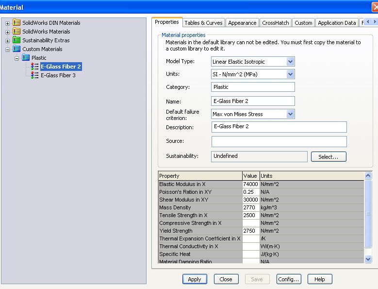
i would like to know please if the properties which i entered in the material e-glass in solidworks are for the fiber only ? or for the fiber with the resine ?

so here is a picture of my steering wheel case which i had to draw in SolidWorks Features
Image
Image

and this is the properties which i entered for glass fiber
Image

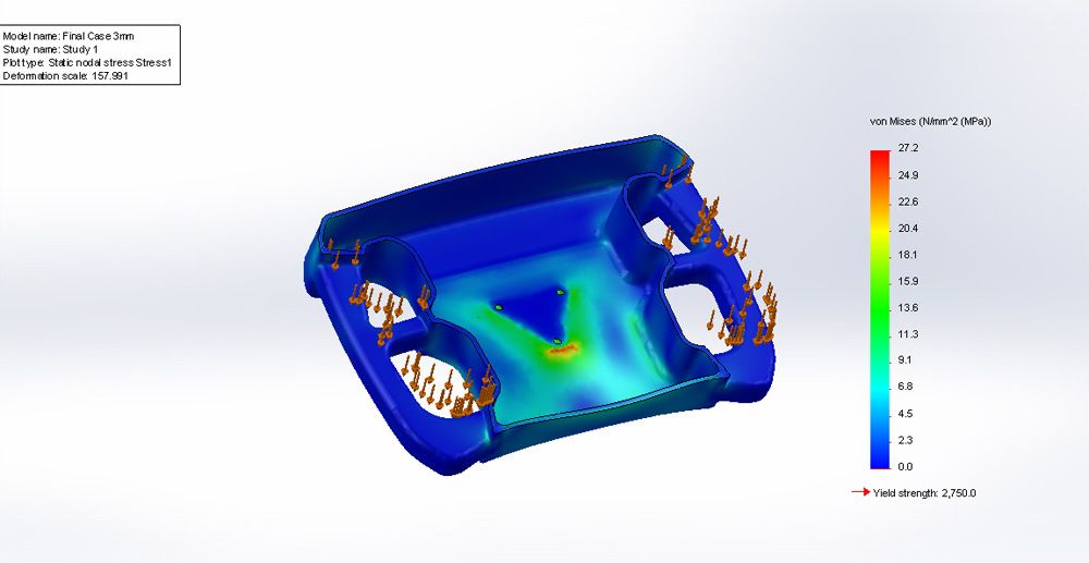
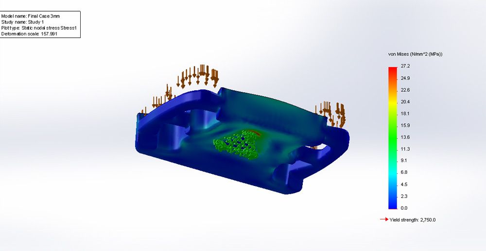
and here is my simulation results choosing the material i made above and a force on where the hand will be places using a force of 100N
Image
Image

so is it possible to make Chopped Strand Mat with solidworks simulation and study it ?

Cold Fussion
Cold Fussion
93
Joined: 19 Dec 2010, 04:51

Re: Fiberglass composite study in SolidWorks, Help !

Post

Do you have much experience working with composites (as in actually building with them)? I ask because the actual layup with composites is a 'dark art' so you might struggle to layup in a representative way to your simulation. Having done a little composite work for FSAE (emphasis on a little), my experience using fibre-glass chopped strand is that you will use a lot of epoxy and probably have a lot of trouble trying to maintain your fibre to matrix ratio. If your goal is to match the simulation to reality, my suggestion would be to get yourself some fibre glass cloth and investigate making your own prepregated fibreglass as you will have a much tighter control of the composition (while also making the final layup much more straight forward). Fibreglass cloth is very cheap, all up the cloth and resin will cost you less than $100 US to mold the steering wheel. I personally hate working with chop strand, it's thick, soaks up a lot of epoxy, is very iritating on the skin and the final results are not very nice.

If you have experience working in composites then ignore everything I've said, as I'm only a beginner.

User avatar
mep
29
Joined: 11 Oct 2003, 15:48
Location: Germany

Re: Fiberglass composite study in SolidWorks, Help !

Post

1. You need to use the material properties of the layup; so the fibres + resin. These will be significantly lower than the fibre properties. Ideally you obtain them from a test part.

2. Is your FE software able to calculate nonlinear and anisotropic materials?
If not you can still use it but you can take the results as rough guide only. The safety margin should be increased quite a lot and lower material properties used.

firasf1dream
firasf1dream
4
Joined: 18 Apr 2014, 21:26

Re: Fiberglass composite study in SolidWorks, Help !

Post

@Cold Fussion i will not be making this myself, i will do it at a professional workshop, i checked his work the guy who owns that workshop it's nice work, he makes part for cars and other than cars

firasf1dream
firasf1dream
4
Joined: 18 Apr 2014, 21:26

Re: Fiberglass composite study in SolidWorks, Help !

Post

mep wrote: 1. You need to use the material properties of the layup; so the fibres + resin.
you mean in the properties in Solidworks the picture i showed ?
mep wrote: These will be significantly lower than the fibre properties. Ideally you obtain them from a test part.
what do you mean lower ?! you mean the material will get closer to the failure value ?!

mep wrote: 2. Is your FE software able to calculate nonlinear and anisotropic materials?
yes it can, i can choose this in the material properties in the picture i showed
mep wrote: If not you can still use it but you can take the results as rough guide only.
the most important is the study and my report, the production is on me it's not necessary to present with the production process but me i choosed to produce this project
mep wrote: The safety margin should be increased quite a lot and lower material properties used.
before i game a thickness of 5mm but i saw the maximum stress value is waaaay far from the yield value so i decided to lower the thickness, you mean should i keep it 5mm in case this simulation is just a guide ?

User avatar
Tim.Wright
330
Joined: 13 Feb 2009, 06:29

Re: Fiberglass composite study in SolidWorks, Help !

Post

100N isn't really a realistic loadcase. Consider the high forces that a steering wheel sees in an impact.

CSM is probably the worst material to choose from both a mechanical performance point of view and also an analysis point of view. Its performance is totally dependent on the type of glass, the size of the strands, the resin used, the layup type (vacuum consolidated or open) and the curing process. Then its heavy, uses a lot of resin and is very weak in comparison with every other material. Also I think you are going to struggle to get such fine geometry with a CSM mat.

There is no datasheet that will tell you how your CSM will behave. You need to make a test part to understand how it behaves. If you are lucky it will behave relatively isotropic because the fibres are randomly oriented.
Not the engineer at Force India

firasf1dream
firasf1dream
4
Joined: 18 Apr 2014, 21:26

Re: Fiberglass composite study in SolidWorks, Help !

Post

Tim.Wright wrote: 100N isn't really a realistic loadcase. Consider the high forces that a steering wheel sees in an impact.
ah ok, well in fact i got that value from F1 regulations article 16.6 it talks about the steering column but i decided to take it as basic value, it says : "The test structure must be solidly fixed to the ground and a solid object, having a mass of 8kg (+1%/-0) and travelling at a velocity of not less than 7meteres/second, will be projected on it."
so from here i made my calculation using the 2nd law of newton and i calculated the force for 1 second
Tim.Wright wrote: CSM is probably the worst material to choose from both a mechanical performance point of view and also an analysis point of view. Its performance is totally dependent on the type of glass, the size of the strands, the resin used, the layup type (vacuum consolidated or open) and the curing process. Then its heavy, uses a lot of resin and is very weak in comparison with every other material. Also I think you are going to struggle to get such fine geometry with a CSM mat.

There is no datasheet that will tell you how your CSM will behave. You need to make a test part to understand how it behaves. If you are lucky it will behave relatively isotropic because the fibres are randomly oriented.
well i when i found myself having only this option, i made some research and asking about the material itself, they told me it's strong because it's in random directions :| ! why ?!
so you suggest i make my study on a unidirectional material ??

about the unidirectional in solidworks, if i defined a thickness of 5mm lets say, then i must decide the thickness of every laminate myself ? if i chose 6 layers, then 5/6mm will be the thickness of every layer ?

User avatar
mep
29
Joined: 11 Oct 2003, 15:48
Location: Germany

Re: Fiberglass composite study in SolidWorks, Help !

Post

You asked if you need to use the material properties of the fibres or fibres + resin. The answer to the question is the later (combined properties of fibres and resin). You will need to present a source for that (important). Those will be different from the properties of the fibres only. I think you can ignore the fact that the material is anisotropic. It seems to be for an academic study only and the chopped strand mats could be seen as quasi isotropic. Makes life easier and you can focus more on the basics. This also means you don’t need to think about individual layers.
Tim is right you should spend some time thinking about your load case. Judging from your pictures it is really not realistic at all. Think that the wheel will experience a moment and that the hand will try to compress it.

firasf1dream
firasf1dream
4
Joined: 18 Apr 2014, 21:26

Re: Fiberglass composite study in SolidWorks, Help !

Post

mep wrote:You asked if you need to use the material properties of the fibres or fibres + resin. The answer to the question is the later (combined properties of fibres and resin). You will need to present a source for that (important). Those will be different from the properties of the fibres only. I think you can ignore the fact that the material is anisotropic. It seems to be for an academic study only and the chopped strand mats could be seen as quasi isotropic. Makes life easier and you can focus more on the basics. This also means you don’t need to think about individual layers.
Tim is right you should spend some time thinking about your load case. Judging from your pictures it is really not realistic at all. Think that the wheel will experience a moment and that the hand will try to compress it.
aha so no layers just go with the thickness ?

about the properties i have those for fibers alone and those of the resine alone so are these you asking about ?

about the steering wheel you mean a torque force ? if a torque force i did some research and made my study based on the regulations of FSAE which says a torque around 660N

firasf1dream
firasf1dream
4
Joined: 18 Apr 2014, 21:26

Re: Fiberglass composite study in SolidWorks, Help !

Post

Guys,
i am thinking about some solution so i came up with this:
what if i made a study with unidirectional fiberglass composite and made every ply in a direction trying to predict in a way or another the attitude of a Chopped Strand Mat, example : [90/67.5/45/22.5/0/0/-22.5/-45/-67.5/-90] for a 10mm thickness laminate and a 1mm for each lamina, it's oriented in many directions, so you thoughts please ?

sgth0mas
sgth0mas
3
Joined: 18 Mar 2015, 03:42

Re: Fiberglass composite study in SolidWorks, Help !

Post

I'm going to add to what a lot of people have said as well as correct/clarify a few points from people.

You have to take the mechanical properties of the COMPOSITE. Using just the glass will be artificially optimistic. Furthermore, the mechanical properties will be largely dependent on the fiber volume fraction. I would actually test a coupon in multiple directions, but it sounds like you may have to just take a VERY conservative guess or contact a few vendors if you don't have the test equipment. I have calculated this for unidirectional fibers and actual woven mat layups, but never chopped so I'm not sure on the formulae. This will NOT behave isotropically because the fibers are only oriented in the X-Y direction for the most part. This composite will also not behave linearly. If this is a masters level class, I cannot imagine they expect you to simplify it down to a linear isotropic problem, but maybe this is not a mechanical/materials degree. I say this because the part will see tension and compression, as well as loads transverse to the fiber orientation. If you treat that isotropically, you will get incorrect answers in the compressive and transverse simulations. If your professor is weak in composites...well then maybe you can rely on over designing the part and forcing a few calculations in the report.

Solidworks actually has a composite layup solver, but I'm not sure if it's a special package. If you have this package, learn to use it as it will help you correlate your proposed hand calculation method of approximating based on Unidirectional fiberglass. If you are familiar with developing the mechanical properties of Ud composites based on volume fraction and resin/fiber properties, then you at least have an idea of what the combining of properties means. But compression and transverse loads are still a different story. If your Vf is around 50% you may try approximating the transverse tensile and all compressive loads as just the resin properties.

Sorry if this is more confusing.

Also, you may want to mount with 4 holes on a square since there is an unbalanced moment about the horizontal axis of the steering wheel when looking at it dead on. This will help the stress riser that is at the lower tip of the "triangle".

firasf1dream
firasf1dream
4
Joined: 18 Apr 2014, 21:26

Re: Fiberglass composite study in SolidWorks, Help !

Post

well yes a bit confusing :( i had only 1 class in composite and i am the first here in my university CNAM to have ever make a composite project, it's not gonna be only steering wheel, i will make a car f1 model from fiberglass, my degree is in Systems
i am really struggling with the material stuff :( and for the properties i had hours of research on the internet to be able to find the properties needed and the most reliable ones,

about solidworks solver what is the exact name of this add in ?

and about the oriented in all directions don't you it will work fine ?

sgth0mas
sgth0mas
3
Joined: 18 Mar 2015, 03:42

Re: Fiberglass composite study in SolidWorks, Help !

Post

firasf1dream wrote:well yes a bit confusing :( i had only 1 class in composite and i am the first here in my university CNAM to have ever make a composite project, it's not gonna be only steering wheel, i will make a car f1 model from fiberglass, my degree is in Systems
i am really struggling with the material stuff :( and for the properties i had hours of research on the internet to be able to find the properties needed and the most reliable ones,

about solidworks solver what is the exact name of this add in ?

and about the oriented in all directions don't you it will work fine ?
Firas, Being a systems guy, I can understand that this is probably quite foreign then. Materials are very difficult, and composites have to be the worst. There is just too much variability based on the layup design and the manufacturing process. It's much easier to use a metal or homogeneous plastic. Knowing that this will not be centered around a mechanical or materials program means you are probably ok to use a lot more assumptions and generalizations. I am sorry for going so technical, I was thinking this was a course based more on mechanical engineering.

Assuming this to be Ud fibers all arranged in random orientations will not work because composites that are continuous fiber are much much MUCH stronger than composites that are chopped fiber (can be over an order of magnitude). This is because of the manner in which the loads are transferred through the resin, the fact that the chopped fibers are relying much more on the resin fiber bond, the fiber density in each direction will not be close to that of a continuous weave with respect to volume fraction...and a host of many other factors.

So my advice to you would be to look up properties of a similar CHOPPED composite and decrease them even more to give yourself margin as has already been suggested by a few of us here. If your design will pass with the strength of just the the resin, then analyze using that too just to detail the amount of margin in your design.

I don't know the name of the solidworks solver...sorry, I use ANSYS almost exclusively.

In short:

-redefine all mechanical loads, as a systems guy you're probably quite familiar with requirements development
-Find the properties of a comparable chopped fiberglass composite (in composite form...not the mat), reduce those properties to give yourself margin, and analyze that. DO NOT USE FIBER STRENGTH OR AN EQUIVALENT Ud COMPOSITE
-Run your simulations based on the loads and parameters you just developed

If you want to post up the results and input parameters again, we can probably give it a shakedown to see if it seems in the ballpark.

Another tip, it is actually possible to make the tensile strength of a plastic lower by adding fibers. In the oil and gas industry, we often use PEEK because it can perform in the environment we need. Many times Fiber filled PEEK is weaker than Virgin Extruded PEEK. The fibers are added for different mechanical reasons aside from pure tensile.