asdf10101 wrote:Hi all
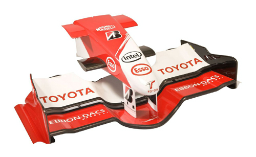
i want to ask for help about my FYP.. im doing a CFD study on the differences between 2008 and 2009 regulations.. i wanted to do a simulation using star-cd star ccm and star design.. my target was to used a simplified front and rear wing.. for example for front wing, i will only use 1 airfoil.. and for rear wing i will use multiple airfoil possibly 3..
so basically i will have 2 front wing (1 for 2008 dimension and 1 for 2009 dimension)
same goes to rear wing..
the aim is to find drag coefficient and lift coefficient and also downforce.. but the problem is
1. i dont know whether it is capable to make FYP not based on publish journal
2. i dont know which airfoil to be used (front and rear)
3. i wanted to prove that 2009 regulation increase the overtaking opportunities but how do i know about it? from Cd or Cl?
another thing i want to ask is.. does the height of a wing affect the downforce? i mean same airfoil size but from different height.
1. let say 1 meter
2. 0.2 meter
and the width does it play a role in downforce?
i think my title will not be successful.. please help me

Sorry, I think your going about it in the wrong way, and I think you've made a bad assumption in choosing a single element front wing.
In this instance, I feel you need to diagnose the problem, and then try to quantify it.
So, we know the front wing downforce dropping off in a car's wake was and still is the problem.
Consider the front wing in isolation, make a proper elemented wing - here are a few profiles to get you going:
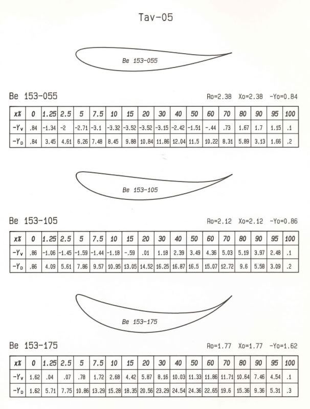
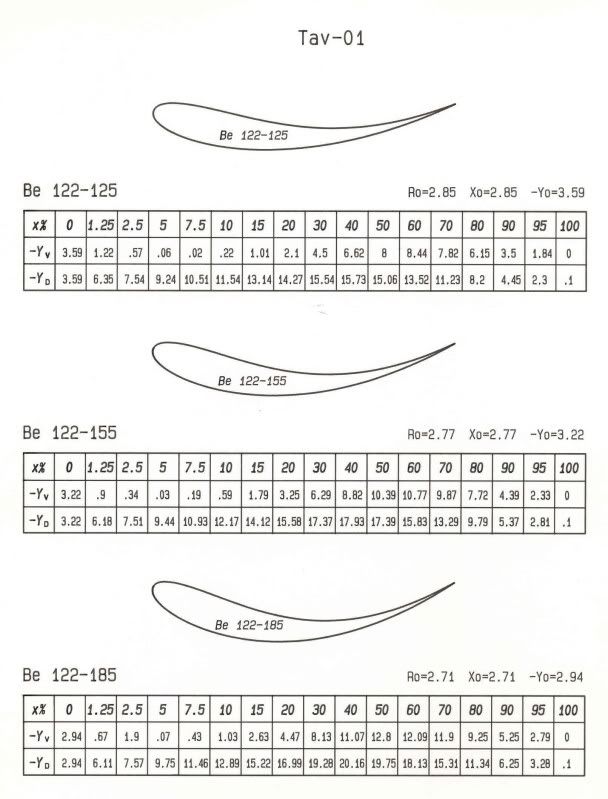
You can build your own basic multi-element wing from this in any CAD package, or probably better, a mesher directly.
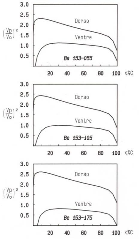
Validate your CFD based on isolated aerofoil performance at 0 degrees angle of attack:
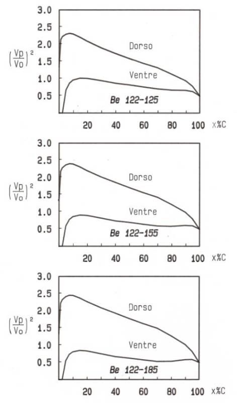
You can then look at the sensitivity of the multi-element wing to both turbulence intensity, and local angle of incidence (different from angle of attack!). I would recommend keeping these as boundary conditions you can explicitly impose, rather than use an upstream diffuser/rear wing combination (although you might want to make one to get an idea of the effects of an upstream diffuser/rear wing on the flow stream.
You need to be careful to avoid your problem growing to unmanageable mesh sizes. So I wouldn't look far beyond an isolated front wing assembly and vary the boundary conditions upstream of it (using set boundaries) to see the effects.
Bite off more than you can chew and you'll make a balls of the whole thing. Keep it simple and compact, then you can properly investigate the area.


