Advantages:
rotary design means more energy efficientcy (regular four or two stroke loses energy when it has to move the piston up and down rapidly - here the piston is revolving evenly)
less vibration (the piston my look offset, but you could make holes in it, so the weight would be even on both sides of the piston - also many pistons would cancel out each other’s vibrations)
The fact that the engine is split-cycle means an even number of cylinders (2, 4, 6, 8 etc.). But since two cylinders in one “pair” are only 1/8 of the cycle away from each other, the two, four or six-cylinder designs may not be possible or may require a flywheel. With 8 cylinders this problem is no longer present, as there is always a piston in every position in the cycle at any given time.
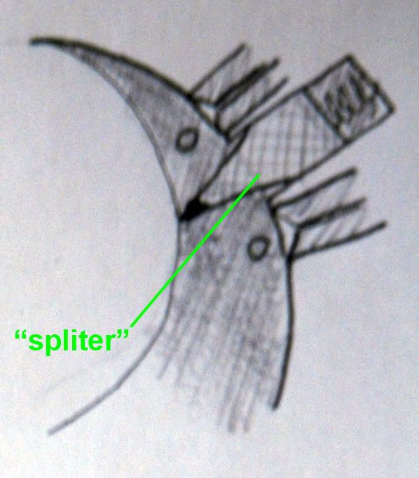
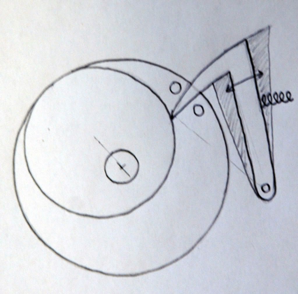
When it comes to number of moving parts both engines (traditional four-stroke and split-cycle rotary) are very similar. A very unique engine part in this design is the “spliter” (pic. 9 and 10). Many designs are possible, but it must always maintain a reliable seal between the chambers (by moving up and down, of course!)
The cycle (see pictures):
1) in the top right we can see the moment of ignition. The compressed fuel-air mixture came from one of the other pistons, due to the split-cycle combustion method (through the opening C - A,B,D are closed). The mixture burns between the piston and the “spliter”, which splits the chamber around the piston into two parts (see pictures 9 and 10). While combustion is taking place in one part of the chamber, the air-fuel mixture is starting to be compressed in the other.
2-3) The pressurized gases continue to push the piston around and compress the air-ful mixture used for combustion in one of the other cylinders. All openings are closed.
4) We can see the pressurized air-ful mixture being forced through D which connects to one of the other pistons (opening C in that other piston). That’s where the compressed mixture from picture 1 comes from. The engine does require some sort of a valve system, which opens and closes the openings and canals.
5-8) Fresh fuel-air mixture is being pumped into the engine through A. The pistons continues to revolve as it pushes the exhaust gases out through B.
If you have any questions or might want to add something, please comment


