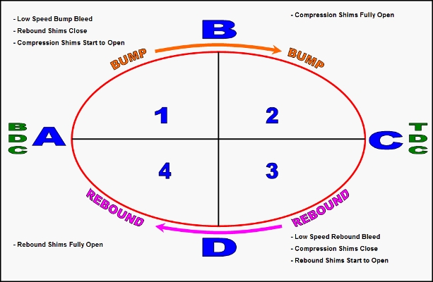
DaveW wrote: I can't think that 747's interpretation is correct (with apologies), because damper displacement was nominally identical for all runs.
No apologies needed Dave, may I expressed myself wrong or maybe I´m completly wrong on this one - it´s quite possible.
What I meaned to say, if I understand the force vs. displacement graph correctly is that to me the graph starts on the left at the BDC (let´s say -25 mm for the sake of the example) then at the middle it passes the 0 point at which you usally have the highest velocity (and therefore in a "normal/perfect" damper the highest force value)
then it continues to the TDC on the far right side (+25 mm).
Therefore we have an (assumed) total displacement of 50 mm going from -25 mm on the far left to +25mm on the far right side of the graph(circle).
As we see higher forces for bump damping with an increase in compression (area from 0mm to +25mm we have a displacement component which seems to give highest value at ~ +8mm of compression.
Your thought of an flexing connection hose/line, or flexing damper body is (as usual) very creditable.
Another possible explainantion is a too low gaspessure, meaning that due to the nonlinearity of an gasspring we see displacement of the seperation piston unless we have a sufficient force to resist the damping forces.


