Exhaust Blown Floor - Forward Exhaust Exit

Here are our CFD links and discussions about aerodynamics, suspension, driver safety and tyres. Please stick to F1 on this forum.
Sayshina
Sayshina
1
Joined: 04 Mar 2011, 21:58

Re: Exhaust Blown Floor - Forward Exhaust Exit

Post

Ringo, that's not a Gurney flap, it's a fence. They're placed parallel to flow to generate a vortex. Also, it could be slotted, but what you're calling a slot gap I suspect is just the reflection off the edge of the matereal it's attacked to.

Mareck, we know this solution is NOT "very powerful". When the high nose first came on the scene, other designers scratched their heads, the originator said "we don't know exactly why it works but it does", and that concept, all by itself, made an otherwise nice handling but very underpowered car a frontrunner. There is no evidence to date that Renault has jumped to the front of the grid, and we know that it's NOT very underpowered. At best it's a small net gain.

When it first showed up on the grid one of the rivals said something along the lines of "with the rules so restrictive this year some teams are going to be chasing some very high risk low reward concepts".

Regarding the machine gun analogy, I see some validity but I should point out that 1100 rounds per minute is pretty much the upper limit, and the gases move at well over supersonic speeds. The entire pulse is long over before the next one begins. The flow inside an exhause is vastly more complex. As but 1 example designers try to tune the sound pulse that comes the exhause valve closing.

User avatar
ringo
230
Joined: 29 Mar 2009, 10:57

Re: Exhaust Blown Floor - Forward Exhaust Exit

Post

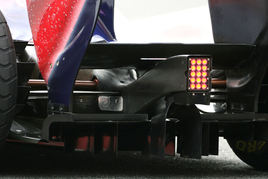
That is not a fence. Nice try though.
Not everything on the car is to generate vortices.

That is a slotted gurney, no different than what you see on the edges of the diffusers and wings.

That little thing wont generate any meaningful vortex.

more examples:

Image

Image
For Sure!!

volarchico
volarchico
0
Joined: 26 Feb 2010, 07:27

Re: Exhaust Blown Floor - Forward Exhaust Exit

Post

ringo wrote:That is not a fence. Nice try though.
Not everything on the car is to generate vortices.

That is a slotted gurney, no different than what you see on the edges of the diffusers and wings.

That little thing wont generate any meaningful vortex.
I agree it's a gurney. Even without the exhaust though, wouldn't the flow in this area have an outward component due to the barge boards and sidepods turning the flow outward and around?

@godlameroso: Unfortunately, I don't think you can discretize air into "bullets". Any subsonic flow has influence upstream and downstream. Sound waves ARE pressure waves so I think they would be fairly analogous.

shelly
shelly
136
Joined: 05 May 2009, 12:18

Re: Exhaust Blown Floor - Forward Exhaust Exit

Post

Agree with volarchico and ringo: it is a gurney.
In that zone of the car, in front of the sidepod, air flows with a very big lateral component, so it really flows form centerline to lateral , and that carbon piece acts like a gurney for the local flow, so volarchico is right.

So who thinks it is not a gurney because it is aligned with the flow is wrong; also it is not correlated with r31 exhaust layout, because every car on the grid sports it: it works witha normal flow, even if its effect will be bigger on r31.

Ringo, you should see these in cfd, it is a very basic flow feature.

As far as the points of the discussion:

-agree that baptising is not that important, but maybe from definition comes information; later we should cover also the pulsation issue

-I think marekk is underestimating, and ringo a bit overestimating. Output density and diameter estimate influence too directly the result- For example I think thet 5cm radius is much bigger than r31 output area, which seems more, for example, a 5x8 axis ellipse. I think that from 38 to 220 we should all converge to one value-range

-behaviuor: it is very complex, but we just need to set some points. For example we can use images like van dyke's or th ones volarchico and marekk posted, to see very roughly how long the coherence of the exahust flow is kept in a free environment(1cm? 1 foot? just the order of magnitude)

-we should figure out, of the exhaust energy, what part is kinetic, what part is pressure, and what part is temperature, and see what is the exploitation of any of these part. What advantage is given by high temperture? What by velocity? and so on.


Then I think we can discuss each car's arrangement, having found a base of shared (maybe not right) estimations
twitter: @armchair_aero

tok-tokkie
tok-tokkie
37
Joined: 08 Jun 2009, 16:21
Location: Cape Town

Re: Exhaust Blown Floor - Forward Exhaust Exit

Post

Sayshina wrote: Regarding the machine gun analogy, I see some validity but I should point out that 1100 rounds per minute is pretty much the upper limit, and the gases move at well over supersonic speeds. The entire pulse is long over before the next one begins. The flow inside an exhause is vastly more complex. As but 1 example designers try to tune the sound pulse that comes the exhause valve closing.
Is this not correct? :
Sound waves are pressure pulses and have nothing to do with fluid flow. Sound travels at the speed of sound irrespective of the fluid flow rate. Silencers (mufflers) do mix the air flow up to even out the pulses in an exhaust so that the noise from the exhaust outlet is reduced - caused by the pulse amplitude.

marekk
marekk
2
Joined: 12 Feb 2011, 00:29

Re: Exhaust Blown Floor - Forward Exhaust Exit

Post

ringo wrote: -what speed could they have

2.4 lt engine
exhaust stroke every 2 cycles which is 9,000 cylces per minute gives 150 exhaust events per second.
for half the engine it's 1.2lt of air per side.

so it's 150 events every second x 1.2 lt = 180 l/s being pumped out

180lt = .18 m3 times the density of air at ambient which is 1.2kg/m3 = 0.216kg/s using density at ambient.

mass flow does not change, so we use ambient to find unchanging mass of air and we stick with this mass from now on.

at 850 degrees, density of air is now 0.31kg/m3 , mass is still the same.


for a pipe diameter of 2.5 inch, it's area = 0.00316 m2

using our known and constant mass of air passing this crossection of exhuast pipe everysecond,

it's velocity = mass flow/[density (at 850C) x area] = 0.216 / 0.31 x 0.00316 = 220m/s

this is maximum speed, but it's a linear relationship. so at 14,000rpm the speed would be 171m/s.
@ringo: are you realy sure there is 850 degree celsius at pipe's exit ?
What is your combustion temperature then ?

By the rules, max combined pipe's exit area is 50,000 mm^2 = 0,05 m^2.
Do you realy think, they'll use 7 times less ?
Last edited by marekk on 19 Mar 2011, 17:54, edited 2 times in total.

marekk
marekk
2
Joined: 12 Feb 2011, 00:29

Re: Exhaust Blown Floor - Forward Exhaust Exit

Post

Sayshina wrote: Mareck, we know this solution is NOT "very powerful". When the high nose first came on the scene, other designers scratched their heads, the originator said "we don't know exactly why it works but it does", and that concept, all by itself, made an otherwise nice handling but very underpowered car a frontrunner. There is no evidence to date that Renault has jumped to the front of the grid, and we know that it's NOT very underpowered. At best it's a small net gain.
My definition of "quite powerful" for F1 car is 0,5s gain in lap time.
Renault may or may not jump to the front of the grid, but they'll did one year ago some serious calculations/simulations and decided to throw a few (tenths ?) millions of dollars at it. R31 is built around this concept, and if they'll manage to close the gap to 0,5s (3-4 tenths still missing because of RK not on the grid this year), then i call it success.

xpensive
xpensive
214
Joined: 22 Nov 2008, 18:06
Location: Somewhere in Scandinavia

Re: Exhaust Blown Floor - Forward Exhaust Exit

Post

If "Renault" is seriously and conciously, injecting their xhausts under the sidepods from the front edge, boy, they're playing around with Bernoulli big-time.

Typically, all you ever do around those sidepods is to make the speed under them higher than overer them, basic stuff.

delta p = rho * (v^2 - v1^2) / 2; Then the downforce will obviously follow as delta p times xposed area.

But that simple formula always had the condition of the same density (rho) on both sides, if you begin to meddle with that, at least I don't have a clue, but perhaps the CFD people at Enstone does?
"I spent most of my money on wine and women...I wasted the rest"

User avatar
ringo
230
Joined: 29 Mar 2009, 10:57

Re: Exhaust Blown Floor - Forward Exhaust Exit

Post

shelly wrote:Agree with volarchico and ringo: it is a gurney.
In that zone of the car, in front of the sidepod, air flows with a very big lateral component, so it really flows form centerline to lateral , and that carbon piece acts like a gurney for the local flow, so volarchico is right.

So who thinks it is not a gurney because it is aligned with the flow is wrong; also it is not correlated with r31 exhaust layout, because every car on the grid sports it: it works witha normal flow, even if its effect will be bigger on r31.

Ringo, you should see these in cfd, it is a very basic flow feature.
Show examples of other cars with this slotted gurney in this same position. And what's the reason for renault not using it until they upgraded the pipes?

The air flow goes laterally but not that far out to the edge of the floor. The latteral motion is closer to the surface of the sidepod. The exhaust is enhancing that component of velocity going over and under the gurney.

That gurney is correlated with the exhuast, it is an attemp to create downforce from the high speed flow over and under that very cambered airfoil shape at the edge of the floor. They are trying to fully exploit every drop of energy from the exhaust.


As far as the points of the discussion:


-I think marekk is underestimating, and ringo a bit overestimating. Output density and diameter estimate influence too directly the result- For example I think thet 5cm radius is much bigger than r31 output area, which seems more, for example, a 5x8 axis ellipse. I think that from 38 to 220 we should all converge to one value-range
I am using a 2.5 inch pipe. if it's 4 inch the speed would be 86 m/s, so yes it is dependent on the diameter of the pipe. But that is still far from 38m/s
But it is understood that the exhaust will be more effective with increased speed. I don't see the desperation to slow it down to 38m/s.


-behaviuor: it is very complex, but we just need to set some points. For example we can use images like van dyke's or th ones volarchico and marekk posted, to see very roughly how long the coherence of the exahust flow is kept in a free environment(1cm? 1 foot? just the order of magnitude)

-we should figure out, of the exhaust energy, what part is kinetic, what part is pressure, and what part is temperature, and see what is the exploitation of any of these part. What advantage is given by high temperture? What by velocity? and so on.


Then I think we can discuss each car's arrangement, having found a base of shared (maybe not right) estimations

You can't figure out these things that you are asking for. Bernouli does not apply or any of those steady state principles and assumptions. They only act as loose guidelines.
The mathematics describing the behavior that the CFD models adhere to is pretty heavy.

The CFD is the best representation, and a speed of 220m/s is correct for a 2.5inch pipe, it's the mass flow that matters.
That speed can't be reduced if there is no increase in the size of the pipe accordingly. If it's 4 inches, which is huge, it's 86m/s.
It can't be 2.5 inch and 38m/s. There is no support for that logic. And if we are looking at average engine speed, the F1 car hardly goes bellow 16,000 rpm in gear change for a fast turn. In a slow turn it could be anywhere between 10,000 and 12,000 rpm.
As it is i am working with maximum engine speed to see the full effect.

Renault would want it to be as hot as possible as well and they probably have the pipes insulated. For full and clear understanding the pipes should be looked at with maximum flow and temperature.

Why the hesitance to believe this thing is blowing along the sides? :)

This is a very consistent and logical theory. Too much evidence for it, and too little evidence against it.

evidence: temperature stickers on top of the floor, wishbones and diffuser end plates.
slotted gurney, similar to those on cars with exhaust blown diffusers.
Temperature chalk on the floor near turning vanes.

this was the first cfd i did for this thread, though the angle of pipe and floor airfoil were arbitrary at the time.
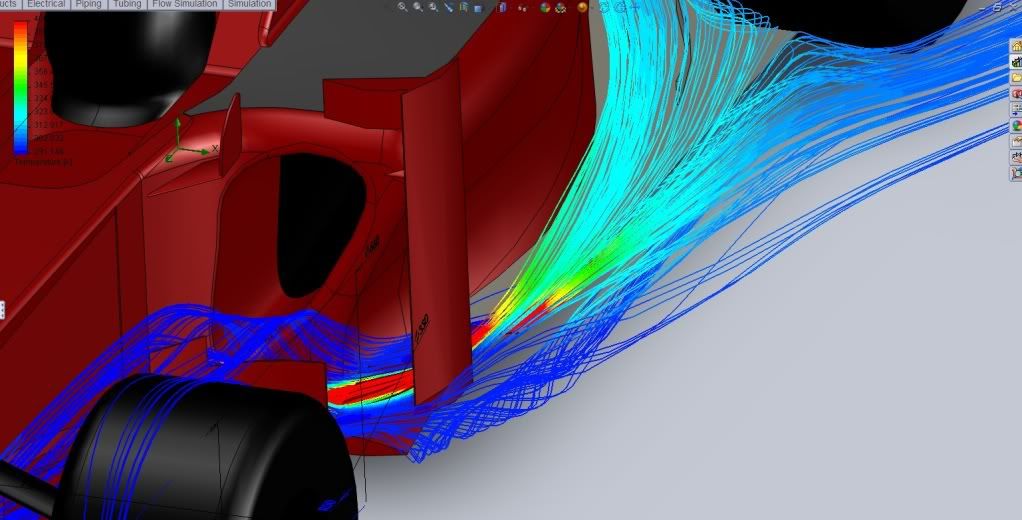
Image
it still goes hand in hand with the gurneys, temp stickers and temp chalk.
For Sure!!

User avatar
ringo
230
Joined: 29 Mar 2009, 10:57

Re: Exhaust Blown Floor - Forward Exhaust Exit

Post

marekk wrote:
@ringo: are you realy sure there is 850 degree celsius at pipe's exit ?
What is your combustion temperature then ?

By the rules, max combined pipe's exit area is 50,000 mm^2 = 0,05 m^2.
Do you realy think, they'll use 7 times less ?


Yep it's 850 degrees from the engine, that's a good estimate. I calculated it at 896 degrees, using some thermodynamics calculation and adiabatic flame temperature.

half the pipe area is 0.025 m2. I simply used a common pipe size which is 2.5 inch.

0.025 m2 is equivalent to a 7 inch diameter per side. Renaults pipe is far from 7 inches. They wouldn't use that anyway, they want to exhuast to be as fast as possible.
For Sure!!

xpensive
xpensive
214
Joined: 22 Nov 2008, 18:06
Location: Somewhere in Scandinavia

Re: Exhaust Blown Floor - Forward Exhaust Exit

Post

ringo wrote: Yep it's 850 degrees from the engine, that's a good estimate. I calculated it at 896 degrees, using some thermodynamics calculation and adiabatic flame temperature.
This would be so impressive if you just for once managed to submit your input data in an orderly fashion.

But that would take an engineer I guess? :lol:
"I spent most of my money on wine and women...I wasted the rest"

BreezyRacer
BreezyRacer
2
Joined: 04 Nov 2006, 00:31

Re: Exhaust Blown Floor - Forward Exhaust Exit

Post

Ringo

Why do you take it from these guys? It's all just a bunch of hyper speculation on their part because they cannot see what the goal is in this design, or refuse to believe it.

Let them do their own research .. oh yaeh, they can't! They just want to chime in about how what you've done has to be wrong .. a bunch of d**ks if you ask me ..

User avatar
ringo
230
Joined: 29 Mar 2009, 10:57

Re: Exhaust Blown Floor - Forward Exhaust Exit

Post

You think this is a talent show case!!?

The exhuast is around 850, and if someone ask me how i get it then i'll say. No sense in show and tell if it doesn't add to the discussion.

ok since it's a show and tell. :roll:

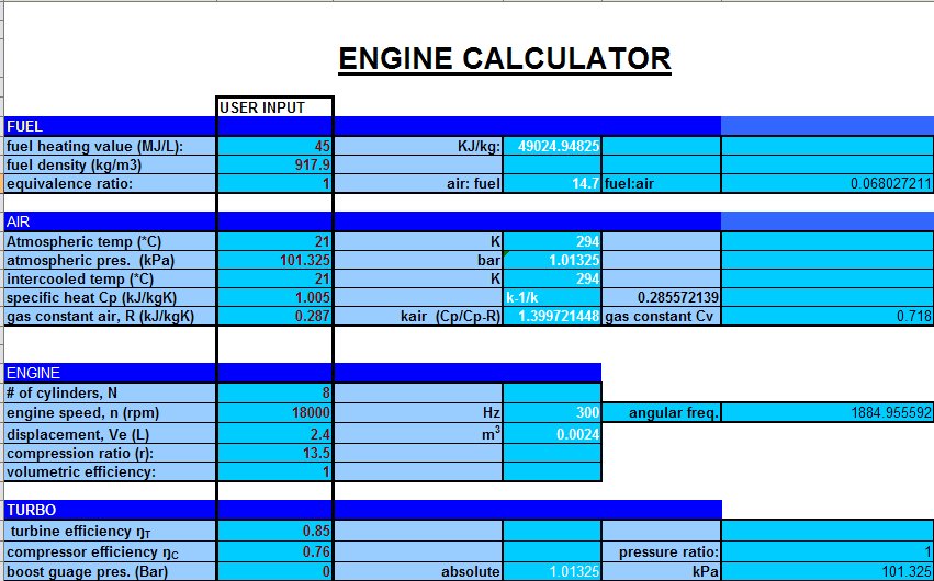
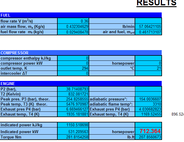
Image
Image

simply little excel file and it's pretty accurate, basic thermodynamics theory.
This was for the 2013 engine thread, it's good for both turbo and non turbo calculation.

What have you contributed Mr. Xpensinve engineer? You're suppose to be expensiive, why all the cheap talk? :mrgreen:
For Sure!!

xpensive
xpensive
214
Joined: 22 Nov 2008, 18:06
Location: Somewhere in Scandinavia

Re: Exhaust Blown Floor - Forward Exhaust Exit

Post

No-no-no, my ambitous friend, that is just some odd engine-chart, which is completely un-interesting for the issue at hand.

What data did you use for what came out of the xhaust-pipes, in other words the input-data for your plots?

Do I have to draw you a map?

-Flow (m^3//s),
-Density(kg/m^3),
-Temperature (K),
-Thermal capacity (Ws/kg*K)
-Thermal conductivity (W/m*K)


Would do fine thank you, unless you want us all your images was just from some software you downloaded from the web?.
"I spent most of my money on wine and women...I wasted the rest"

User avatar
ringo
230
Joined: 29 Mar 2009, 10:57

Re: Exhaust Blown Floor - Forward Exhaust Exit

Post

Odd engine chart. :lol:
You're purposely doing this aren't you?

as for these:

-Flow (m^3//s), I don't use this for the exhaust, i use mass flow.
-Density(kg/m^3), preset by the program, i can change it if i feel. program has materials library with physical properties of different materials.
-Temperature (K), 303 Kelvin for ambient
-Thermal capacity (Ws/kg*K) I don't alter this, this is preset.
-Thermal conductivity (W/m*K) I don't alter this for the air. In fact i run the CFD as adiabatic, meaning only thermal interaction of the air is calculated.
It doesn't calculate for conduction in the car body itself. It's not necessary and my PC would struggle.
Then there're other little things like surface roughness, and turbulence intensity.
humidity.

Here's an example of what can be done.
http://www.youtube.com/watch?v=vIxK6K-X ... re=related
Solid works is pretty simple to use and the inputs are straight forward.
The inputs is the critical part. Garbage in garbage out. I guess this guy is using is odd intake pressure chart as his inputs.
For Sure!!