shelly wrote:Agree with volarchico and ringo: it is a gurney.
In that zone of the car, in front of the sidepod, air flows with a very big lateral component, so it really flows form centerline to lateral , and that carbon piece acts like a gurney for the local flow, so volarchico is right.
So who thinks it is not a gurney because it is aligned with the flow is wrong; also it is not correlated with r31 exhaust layout, because every car on the grid sports it: it works witha normal flow, even if its effect will be bigger on r31.
Ringo, you should see these in cfd, it is a very basic flow feature.
Show examples of other cars with this slotted gurney in this same position. And what's the reason for renault not using it until they upgraded the pipes?
The air flow goes laterally but not that far out to the edge of the floor. The latteral motion is closer to the surface of the sidepod. The exhaust is enhancing that component of velocity going over and under the gurney.
That gurney is correlated with the exhuast, it is an attemp to create downforce from the high speed flow over and under that very cambered airfoil shape at the edge of the floor. They are trying to fully exploit every drop of energy from the exhaust.
As far as the points of the discussion:
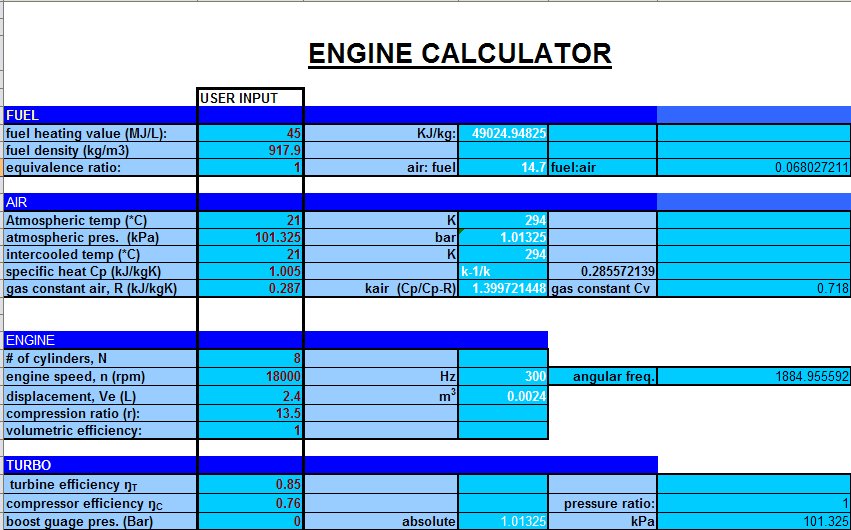
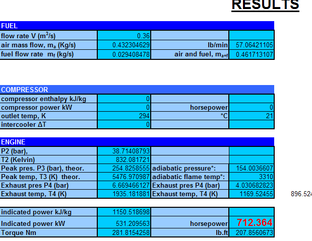
-I think marekk is underestimating, and ringo a bit overestimating. Output density and diameter estimate influence too directly the result- For example I think thet 5cm radius is much bigger than r31 output area, which seems more, for example, a 5x8 axis ellipse. I think that from 38 to 220 we should all converge to one value-range
I am using a 2.5 inch pipe. if it's 4 inch the speed would be 86 m/s, so yes it is dependent on the diameter of the pipe. But that is still far from 38m/s
But it is understood that the exhaust will be more effective with increased speed. I don't see the desperation to slow it down to 38m/s.
-behaviuor: it is very complex, but we just need to set some points. For example we can use images like van dyke's or th ones volarchico and marekk posted, to see very roughly how long the coherence of the exahust flow is kept in a free environment(1cm? 1 foot? just the order of magnitude)
-we should figure out, of the exhaust energy, what part is kinetic, what part is pressure, and what part is temperature, and see what is the exploitation of any of these part. What advantage is given by high temperture? What by velocity? and so on.
Then I think we can discuss each car's arrangement, having found a base of shared (maybe not right) estimations
You can't figure out these things that you are asking for. Bernouli does not apply or any of those steady state principles and assumptions. They only act as loose guidelines.
The mathematics describing the behavior that the CFD models adhere to is pretty heavy.
The CFD is the best representation, and a speed of 220m/s is correct for a 2.5inch pipe, it's the mass flow that matters.
That speed can't be reduced if there is no increase in the size of the pipe accordingly. If it's 4 inches, which is huge, it's 86m/s.
It can't be 2.5 inch and 38m/s. There is no support for that logic. And if we are looking at average engine speed, the F1 car hardly goes bellow 16,000 rpm in gear change for a fast turn. In a slow turn it could be anywhere between 10,000 and 12,000 rpm.
As it is i am working with maximum engine speed to see the full effect.
Renault would want it to be as hot as possible as well and they probably have the pipes insulated. For full and clear understanding the pipes should be looked at with maximum flow and temperature.
Why the hesitance to believe this thing is blowing along the sides?

This is a very consistent and logical theory. Too much evidence for it, and too little evidence against it.
evidence: temperature stickers on top of the floor, wishbones and diffuser end plates.
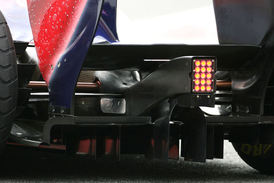
slotted gurney, similar to those on cars with exhaust blown diffusers.
Temperature chalk on the floor near turning vanes.
this was the first cfd i did for this thread, though the angle of pipe and floor airfoil were arbitrary at the time.
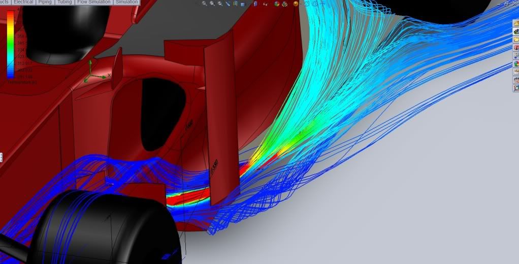
it still goes hand in hand with the gurneys, temp stickers and temp chalk.