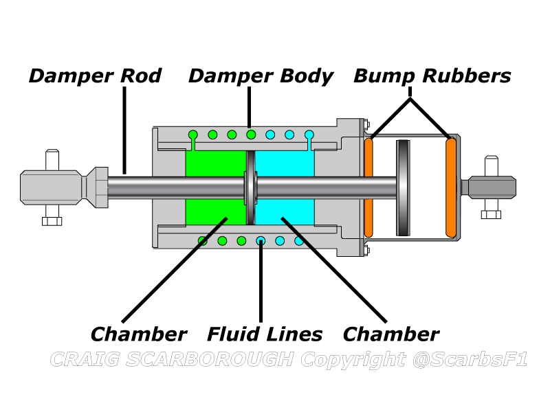
thisisatest wrote:the thing works by pushing mercury around. the mercury exits one chamber and goes on a roller coaster ride around and around the inerter body, re-entering at the other side. they picked mercury because it's very heavy.
during shaft acceleration, the piston accelerates mercury through the tubes. the mercury's inertia provides resistance. at a constant shaft speed, the resistance should be close to zero. (i wonder about the size of the orifice for the coiled tubes, and how much resistance is created there).
it is the fluid version of the inerter that pushes a threaded shaft that in turn spins a mass. i find it easier to see how the mechanical one works, and to see how the fluid one resembles the mechanical one, than to see how the fluid one works directly. like i said, i get stuck on the port size to the coiled tube, seems to me it would provide some damping there where the mechanical one would not...
or does the mechanical one suffer from some friction on its threads, bearings notwithstanding? the article did mention frequent regreasing...
Your post doesn't seem very sure. I want to learn this thing you see.
The problem is the word inerter. I am thinking of vibration absorber.
I will show the theory behind the vibration absorber, but i'll first read on the inerter and see if it's the same thing. See if i'm lost in translation.
edit:
a good read for those interested:
http://www-control.eng.cam.ac.uk/~mcs/lecture_j.pdf
need to brush up on your maths to fully appreciate it. I learned that what i was proposing was an older method to a similar problem, but the inerter is different in principle.
Hope this is good raw information for those who might want to do a little tinkering.
I am reading the first article posted by bryan as well. The thing is basically a capacitor.
That's all i was asking. There was too much techno jargon for such a straight and direct answer.
Conclusion the benefits of a capacitor in an electrical circuit should apply to a mechanical system as well.


