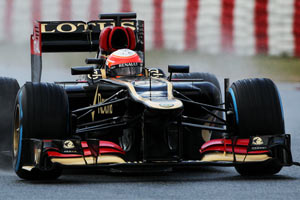
Lotus E21 Renault

A place to discuss the characteristics of the cars in Formula One, both current as well as historical. Laptimes, driver worshipping and team chatter do not belong here.
korzeniow
korzeniow
24
Joined: 03 Feb 2010, 03:51
Location: Cracow/Poland

Re: Lotus E21 Renault

Post

csponton wrote:is this what you mean?
The air intakes on the sides of the airbox ("ears in the case of Lotus, slit for Mercedes) gather a flow of air that is led by means of appropriate internal passages in the end region of the bonnet to be ejected in the area of the monkey seat . in this particular area of the car it will then create a low pressure that is exploited to draw air from the slots and through a tube, inserted inside the central support of the wing, is ejected. and where it is expelled? This low pressure will be created only at high speeds when the air flow rate will have an elevated pressure. In this way, the system will operate in a straight line while when the car has need of downforce (the slower parts) the system will not work because the low pressure that creates us in the area of the Monkey seat will not be such as to "activate" the aspiration. So there would be two separate channeling: the first port that air daii'air box towards the terminal part of the car and the second that draws air from the bottom of the wing profile and exploiting the support of the latter expels. The quantity of sucked air is minimal compared to what comes from the "ears" on the sides of the air box but is such as to create a disturbance in the affected area to create the "stall"
How come the air from the ears create low pressure at exit? It's definatelly high pressured air that comes out with high speed, given the size of the ears.

Monkey seat is too small (10 centimeters wide) to create any significant low presure zone. And it is in "open environment" contrary to the diffuser for example, where the low pressure is between ground and the floor.
It's been a long time since we drove last time, but it has also been a short time at the same time
Roam Grosjean ponders the passing of time on the first day of testing at Jerez
February 5, 2013

Matt Somers
Matt Somers
179
Joined: 19 Mar 2009, 11:33

Re: Lotus E21 Renault

Post

Shelly's sucking version holds some similarities to my original musings on the E20's DRD - http://somersf1.blogspot.co.uk/2012/09/ ... ction.html However I'm reliably informed that when I made the assumption that using the periscope to keep flow attached at lower speed only for it's task to be overwhelmed at higher speed would cause the Wing to stall is incorrect. The simple explanation in this case appears to be the correct one - Airflow enters the 'Ears' and is sent down the engine cover to the rear of the car where it's extracted with the normal airflow (where it would appear there are 2 exits, splitting the flow internally)
Image
When the outlet reaches a point at which it cannot extract the air quick enough it allows the airflow to travel up the Periscope to the under side of the Mainplane disturbing the airflow in that region and stalling the wing.
Image

I've done my best to explain this in my most recent post: http://somersf1.blogspot.co.uk/2013/02/ ... -drag.html
Catch me on Twitter https://twitter.com/SomersF1 or the blog http://www.SomersF1.co.uk
I tweet tech images for Sutton Images

User avatar
amouzouris
105
Joined: 14 Feb 2011, 20:21

Re: Lotus E21 Renault

Post

Matt Somers wrote:Shelly's sucking version holds some similarities to my original musings on the E20's DRD - http://somersf1.blogspot.co.uk/2012/09/ ... ction.html However I'm reliably informed that when I made the assumption that using the periscope to keep flow attached at lower speed only for it's task to be overwhelmed at higher speed would cause the Wing to stall is incorrect. The simple explanation in this case appears to be the correct one - Airflow enters the 'Ears' and is sent down the engine cover to the rear of the car where it's extracted with the normal airflow (where it would appear there are 2 exits, splitting the flow internally)
http://1.bp.blogspot.com/--fbtWsK3OXI/U ... 419+x2.jpg
When the outlet reaches a point at which it cannot extract the air quick enough it allows the airflow to travel up the Periscope to the under side of the Mainplane disturbing the airflow in that region and stalling the wing.
http://4.bp.blogspot.com/-6mBTNTEe8cU/U ... am-2-5.png

I've done my best to explain this in my most recent post: http://somersf1.blogspot.co.uk/2013/02/ ... -drag.html
Completely agree with you!

korzeniow
korzeniow
24
Joined: 03 Feb 2010, 03:51
Location: Cracow/Poland

Re: Lotus E21 Renault

Post

Matt Somers wrote:Image
I don't get this picture. If author assumes that the air from airbox exits trough the mokney seat (orange color) then from where the engine gets its air necessary for the combustion?
It's been a long time since we drove last time, but it has also been a short time at the same time
Roam Grosjean ponders the passing of time on the first day of testing at Jerez
February 5, 2013

User avatar
Lurk
2
Joined: 13 Feb 2010, 20:58

Re: Lotus E21 Renault

Post

It is ok if we assume a splited airbox; it was not uncommon. The upper part was used for cooling the gearbox while the lower part get to the engine. Ferrari even had a problem some years ago (maybe F60?), the split panel was impacting engine performance and they redesigned it during the season.

User avatar
hollus
Moderator
Joined: 29 Mar 2009, 01:21
Location: Copenhagen, Denmark

Re: Lotus E21 Renault

Post

Image (Thanks to F1fanatic)

In this picture it almost looks like those ears are not covering future channels, but already building very thin channels themselves. Alternatively, the first 3 cm or so might be detachable to uncover the real channels, but the ears are not a quick add-on for testing, look how seamlessly they integrate with the main air intake above Romain's "a".
In either case, they are significantly behind the main intake, and I can only think of a good reason for that: to be shadowed by the engine's main intake. It is plausible that they might act as a directional control for the passive DRD:
a) If the car is turning with significant yaw, one of them will get shadowed and ingest significantly less air. I assume that they merge further down and in that case the additive flow is less than without yaw. This would reduce the tendency of the system to activate while cornering.
b) If the throttle if off, as Zonk suggests, the main air intake will suffer spillage, ruining the flow into these eras. This would also reduce the tendency of the system to activate while cornering (if you corner at full throttle, then you don't care too much if it activates), and it would also disable the system while braking.
Both effects would favor adjusting the system with a lower activation speed. Did Lotus shine in the speed traps in Jerez when they tested it?
Rivals, not enemies.

User avatar
Blackout
1566
Joined: 09 Feb 2010, 04:12

Re: Lotus E21 Renault

Post

The 'ears' could feed the gearbox's rad AND the DRD. Ferrari and Mclaren did that in 2010 AfAIR

Arunas
Arunas
4
Joined: 29 Oct 2010, 22:14

Re: Lotus E21 Renault

Post

Blackout wrote:The 'ears' could feed the gearbox's rad AND the DRD. Ferrari and Mclaren did that in 2010 AfAIR
If these "ears" are necessary for cooling of anything or dealing with air spillage from main airbox, they would be not closed in testing and during half of last season, seems to me. These definitelly must be for other purposes.

User avatar
RicerDude
27
Joined: 10 Sep 2012, 20:21

Re: Lotus E21 Renault

Post

Image

Surely an intake like this would produce less drag?

Neno
Neno
-29
Joined: 31 May 2010, 01:41

Re: Lotus E21 Renault

Post

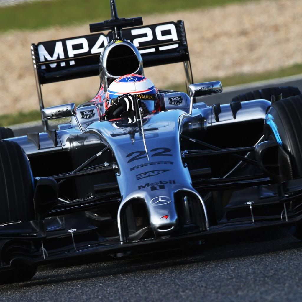
Every team has is own philosophy, this picture of Mclaren "ears" is special for them, because mclaren always using low profile chassis this was their design until this year, giving their philosophy of air going over, not under chassis work for them better if "ears" are up not aside like on Lotus.
Lotus on other side, have philosophy of higher chassis, air going under the car and aside, not over. if they adapt mclaren design of ears chassis aleady highed would not work with ears ahed airbox because of air resistance.

this is only logical explanation for me.

User avatar
hollus
Moderator
Joined: 29 Mar 2009, 01:21
Location: Copenhagen, Denmark

Re: Lotus E21 Renault

Post

This is what I mean. Blue is flow for the engine, red for the DRD.

Image
Rivals, not enemies.

User avatar
TEHNOS
8
Joined: 03 Nov 2011, 19:02

Re: Lotus E21 Renault

Post

Image

Image

Image

shelly
shelly
136
Joined: 05 May 2009, 12:18

Re: Lotus E21 Renault

Post

I will try to explain myself better I have seen that some of the things I have said are not clear.

In my opinion the small periscope pipe draws air in, does not blow it out. I have come to that idea after reading some other posts and blogs, like somers' (which I liked) or scarbs', without being able to fix some things that seems inconsistent to me. If I tried to reverse, all the pieces I was missing seem to find their place.
I will try to itemize the things I did not understand:

- slot position: the f-duct in 2010 used blowing to stall the wing, but since then the rules have banned slots in the wings - so to go around that rule, the slots are placed in a different place, under the wing. In the first e20 drd version they were like this
Image
on the e21 there is a slot pointing upwards (maybe some piece has not been shown yet?), like on the w03.
With the slots being placed there, to me it seems easier to cause stall if you get some air to go into the slit instead of blowing. The trajectory of the flow along the lower surface of the wing is curved, so to cause stall you have to disurb this curved path by putting in place an opposite pressure gradient, with lowered pressure on the outside of the curved trajectory. Thsi can be seen as a local increase in angle of attack. By blowing, you instead decrease this angle - create more favourable conditions for attachment.
Having the wing blown at low speeds to help

- stall behaviour: If I suppose that stall is achieved by blowing out of the slot, after stalling the suction peak on the wing is lost, so the pressure is higher and the hypotetical blowing is less effective, which could lead to reattachment. That seems undesirable. By sucking instead, the higher the pressure on the lower part of the wing, the greater the suction effect

-flow viz: though I am not an expert in interpreting flow viz, in the picture above that shows the separated wing I did not recognize a separation pattern on the slotted pillar, which I expected if the slots were blowing. )But maybe I have wrong expectation - this is not a strong point)

-pipe sizes: when I took a look at renault's f-duct on another thread here http://www.f1technical.net/forum/viewto ... 0&start=15, I noticed that the pipes were sized very differently:
Image
the ears were much smaller, the pipe blowing on the wing and the other pipe discharging between mainplane and beamwing had more or less the same section. On the drd there are much bigger ears, that feed a big main duct, with a much smaller pericope duct - if the working principle is the same, expect for the "passive" switching instead of driver operated, why are the pipes' sizes that different?

-fluidic switch: I have seen no hypotesis about how it could work, and it is difficult for me to imagine one. If I suppose that the periscope is drawing air in, there is no need for a fluidic switch, you need just a venturi section (from there comes the analogy with a mr proper spray)

-monkey seat on the outlet: if the periscope is blowing above a certain speed when the main pipe cannot expel any more flow, why is the big monkey seat needed? In 2013 lotus have got rid of the big monkey seat, but they still need the tongue after the exit of teh main pipe to drive the fluid. If the periscope is sucking and there is a throat in the main pipe to achieve the lower pressure needed, then the monkey seat is necessary to pull the flow out from the throat

-shape of the periscope / main pipe junction: it seems consistent with a 90° connection between periscope and main pipe, which is not necessary if the slots are blowing, whereas it is if the slits are sucking it is needed. But it is difficult to detect the exact shape of teh joint, so this is not a strong point either.

Sorry for the long post
twitter: @armchair_aero

miguelalvesreis
miguelalvesreis
17
Joined: 12 May 2012, 13:38

Re: Lotus E21 Renault

Post

Pressure below the wing, even after being stalled will be always greater or equal to the one on the edge of the pipe.

On the other way, sucking will only be real and effective with pressure differential present. If stall occur then you'll have a near zero velocity in that area (just outside the edge of the pipe) therefore, ambient pressure. You will only have sucking if you can have less pressure on the outside of the pipe exit then on the pipe itself, as saying, if you have RAM effect on the pipe.

I'm not sure if this is the base of what you are saying. But makes sense to me.

They will feed air to a pipe and the output is due to the sub-pressure on the boundary. without any sub-pressure the air would spill to areas with lesser pressure, like the monkey seat area.

User avatar
raymondu999
54
Joined: 04 Feb 2010, 07:31

Re: Lotus E21 Renault

Post

I wonder - could the reason for using 2 inlets instead of 1 be that instead of some pressure level trigger, they're using yaw as a triggering mechanism? In yaw one side will probably get more air - and generally speaking, they'll get equal amounts of air on both sides when on a straight.
失败者找理由,成功者找方法