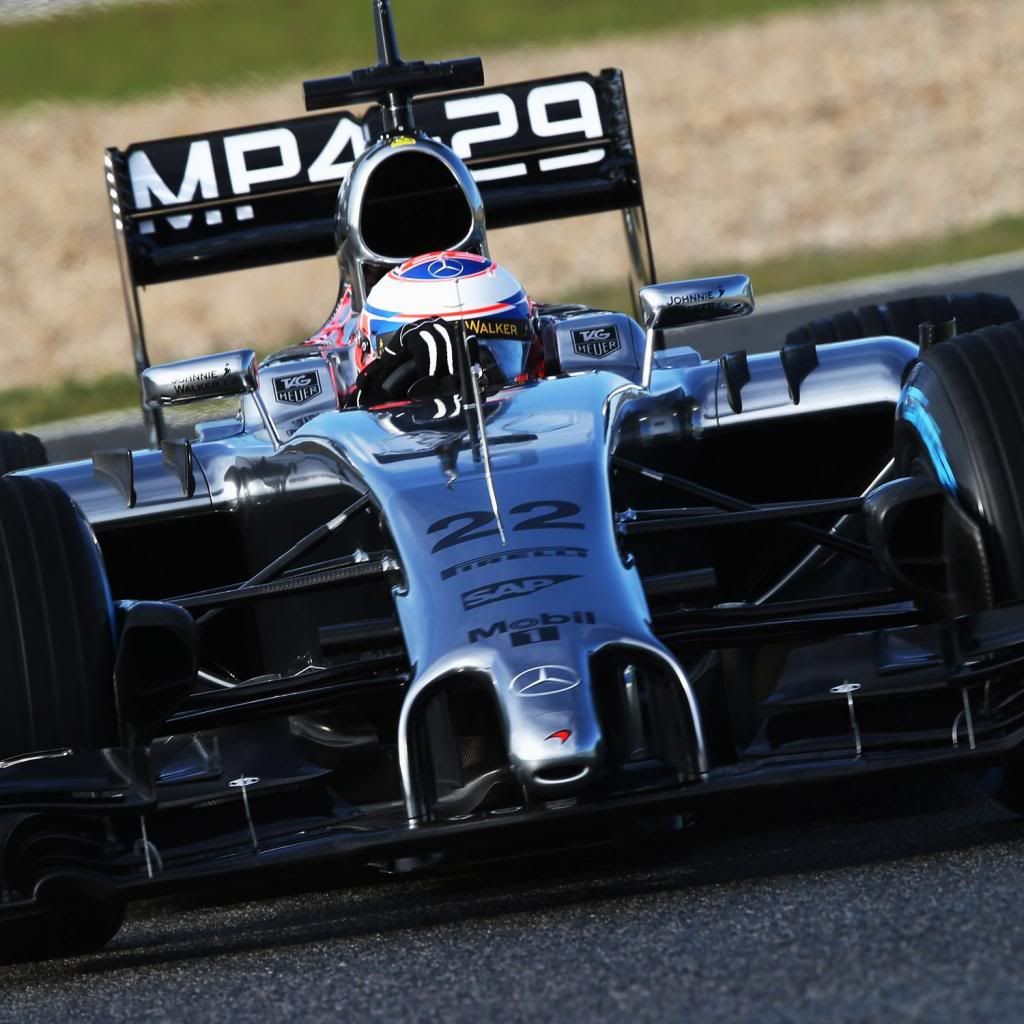

The FW took a big long narrow section off the underneath of the nose, the length pointed out by arrows. It's more obvious in the frame-by-frame.


No, the *upper* side is the modesty panel. The tip of the nose is meant to be the crash structure, and strong enough to actually absorb some energy from a crash.timbo wrote:Of course, as the tip of the nose is modesty panel.
The tip of the nose is higher than where actual nose can be. Anyway, from the pics it is clear that top of the nose incl tip is not bearing loads from the front wing, as it should be.beelsebob wrote:No, the *upper* side is the modesty panel. The tip of the nose is meant to be the crash structure, and strong enough to actually absorb some energy from a crash.timbo wrote:Of course, as the tip of the nose is modesty panel.


agreed. The construction behind the vanity panel, IMO, would never have held that wing in place with that remaining wing.turbof1 wrote:I think the pylons are still placed on the actual nose cone.
I think you're right. The load-bearing portion of the pylons does attach to the structural nose. The forward face of the pylons - down to a certain point - is part of the one-piece modesty panel in order for the whole solution of an effectively higher nose to satisfy 3.7.9's minimum concave radius requirements as well as the regulations which govern the placement of the wing.turbof1 wrote:I think the pylons are still placed on the actual nose cone.
Note the "non structural" in the rule – that means the front wing can not be attached to it... that would make it part of the car's structure.bhallg2k wrote:timbo was correct here. The tip of the structural nose is behind and below (or inside) that of the one on the modesty panel. It's an exploitation of this rule:
3.7.9
With the exception of an optional, single piece, non-structural fairing of prescribed laminate (whose precise lay-up may be found in the Appendix to the regulations) which may not be more than 625mm above the reference plane at any point, no bodywork situated more than 1950mm forward of rear face of the cockpit entry template may be more than 550mm above the reference plane.
The external surface of any longitudinal or lateral cross section taken through the above
fairing may contain no concave radius of curvature less than 50mm.
http://i.imgur.com/cb55oea.jpg
Well done.Huntresa wrote:So i was correct when i said they used the trick back when this car was rlsed...