2014 Design

Here are our CFD links and discussions about aerodynamics, suspension, driver safety and tyres. Please stick to F1 on this forum.
avatar
avatar
3
Joined: 13 Mar 2009, 22:01

Re: 2014 Design

Post

Going back a couple of pages onto intercooler positioning.

A couple of elements to consider:
- smaller engine
- less fuel- smaller fuel cell

Are the ERS/KERS/turbo turbine able/going to be in one unit? (excl. Batteries/control electronics/manifold)

If so, there's surely scope (assuming the turbo exhaust can be a bit on the short side) for using space freed up behind the driver?

I'm thinking wedge the IC slightly in front, but with airflow along the flanks of the engine (under the cylinders), raise the fuel cell (quite a bad idea) and feed as much channelled air (from upstream) as you can muster behind the driver into the gap under the fuel cell.

Rads may need to move backwards to open up a more direct inlet to go with other air channelled/ducted from upstream. Moving the rads backwards may choke off the coke-bottle area somewhat.

I like the neatness of stuffing the IC down there, but there's a couple of big compromises and I'm not sure where the turbo/airbox connection get routed, which may mean it's not workable.

Any thoughts from real engineers on that layout?

::stands back and waits to be shot down::

wuzak
wuzak
467
Joined: 30 Aug 2011, 03:26

Re: 2014 Design

Post

avatar wrote:Going back a couple of pages onto intercooler positioning.

A couple of elements to consider:
- smaller engine
- less fuel- smaller fuel cell

Are the ERS/KERS/turbo turbine able/going to be in one unit? (excl. Batteries/control electronics/manifold)

If so, there's surely scope (assuming the turbo exhaust can be a bit on the short side) for using space freed up behind the driver?

I'm thinking wedge the IC slightly in front, but with airflow along the flanks of the engine (under the cylinders), raise the fuel cell (quite a bad idea) and feed as much channelled air (from upstream) as you can muster behind the driver into the gap under the fuel cell.

Rads may need to move backwards to open up a more direct inlet to go with other air channelled/ducted from upstream. Moving the rads backwards may choke off the coke-bottle area somewhat.

I like the neatness of stuffing the IC down there, but there's a couple of big compromises and I'm not sure where the turbo/airbox connection get routed, which may mean it's not workable.

Any thoughts from real engineers on that layout?

::stands back and waits to be shot down::
Fuel tank and energy store will be in the survival cell. There isn't going to be any room to duct air through there, so air will have to come form the sidepods anyway.

Gaz.
Gaz.
4
Joined: 24 Jul 2010, 09:53

Re: 2014 Design

Post

avatar wrote:Going back a couple of pages onto intercooler positioning.

A couple of elements to consider:
- smaller engine
- less fuel- smaller fuel cell

Are the ERS/KERS/turbo turbine able/going to be in one unit? (excl. Batteries/control electronics/manifold)

If so, there's surely scope (assuming the turbo exhaust can be a bit on the short side) for using space freed up behind the driver?

I'm thinking wedge the IC slightly in front, but with airflow along the flanks of the engine (under the cylinders), raise the fuel cell (quite a bad idea) and feed as much channelled air (from upstream) as you can muster behind the driver into the gap under the fuel cell.

Rads may need to move backwards to open up a more direct inlet to go with other air channelled/ducted from upstream. Moving the rads backwards may choke off the coke-bottle area somewhat.

I like the neatness of stuffing the IC down there, but there's a couple of big compromises and I'm not sure where the turbo/airbox connection get routed, which may mean it's not workable.

Any thoughts from real engineers on that layout?

::stands back and waits to be shot down::
***caution, I don't know what I'm talking about***

Could the intercooler be positioned inside the current style airbox? The inlet air has to pass through the intercooler downstream of the turbo anyway which is being cooled by the ambient air and being drawn through by the intercooler fins by the turbocharger. Would the negatives of a higher intake temperature be outweighed by the aerodynamic positives of not requiring two extra holes to service & package the intercooler in one of the sidepods?

:::also stands back & waits to be shot down:::
Forza Jules

rjsa
rjsa
51
Joined: 02 Mar 2007, 03:01

Re: 2014 Design

Post

That would be the moto continuum of cooling.

piast9
piast9
20
Joined: 16 Mar 2010, 00:39

Re: 2014 Design

Post

I don't think you may cool the air with the air you wan to cool.

User avatar
markc
4
Joined: 08 Dec 2011, 01:30

Re: 2014 Design

Post

wuzak wrote:
trinidefender wrote:Well then here you have to figure out exactly where is considered the compressor inlet. The intake above the drivers head doesn't have to be the exact compressor inlet, it can just have an air path leading to it
Doesn't matter what is considered the compressor inlet.

The question was about using some of the compressed air from the turbo (ie off the compressor outlet) to do other things - like blow the diffuser or create a double DRS effect.

But since all the air that goes into the compressor has to go through the exhaust, you cannot siphon air off the compressor.

You could do what you suggest - but that is no different than now. Although they do not use air from the airbox to do that - they have a separate air inlet. And I would expect much the same in 2014.
Well, the question wasn't thought out fully when asked but I'd never intended to suggest using the turbo directly, the idea is to use the aspirator effect to suck more air in via the airbox thanks to the inlet of the compressor sucking in its air. I talked to an F1 chum who confirmed it's an option but the issue is too much air and what to do with it? Plus the issue of combined gas law previously implied; compressed air is hot. So you'd have a situation where you'd need to tune it to get the right effect, but in principle you can redirect the air (subject to rules governing the airbox / turbo inlet location) to cool the car even when the car isn't moving, but the turbo is working.

That's ultimately where the idea started from; cooling the car when stationary, given fans are banned but the turbo is a fan that runs as the engine runs.

henra
henra
53
Joined: 11 Mar 2012, 19:34

Re: 2014 Design

Post

One thing that crossed my mind regarding the general layout of next year's cars is whether we will see air intakes other than those above the drivers head like we see in today's cars.
With a Turbo engine that is not an absolute prerequsite any more and with the shallower rear wings getting as much uncompromised air to the rear wing as possible might be of some benefit. Extracting the air from the side(s) of the center section where the air is dirty anyway and no beam wing to feed anymore might be worth investigating.
Did I oversee something stating that this would be illegal under the new regs?

wuzak
wuzak
467
Joined: 30 Aug 2011, 03:26

Re: 2014 Design

Post

henra wrote:One thing that crossed my mind regarding the general layout of next year's cars is whether we will see air intakes other than those above the drivers head like we see in today's cars.
With a Turbo engine that is not an absolute prerequsite any more and with the shallower rear wings getting as much uncompromised air to the rear wing as possible might be of some benefit. Extracting the air from the side(s) of the center section where the air is dirty anyway and no beam wing to feed anymore might be worth investigating.
Did I oversee something stating that this would be illegal under the new regs?
3.16.1 With the exception of the opening described in Article 3.16.3, when viewed from the side, the car must have bodywork in the area bounded by four lines. One vertical 1330mm forward of the rear wheel centre line, one horizontal 550mm above the reference plane, one horizontal 925mm above the reference plane and one diagonal which intersects the 925mm horizontal at a point 1000mm forward of the rear wheel centre line and the 550mm horizontal at a point lying 50mm forward of the rear wheel centre line.

Bodywork within this area must be arranged symmetrically about the car centre line and, when measured 200mm vertically below the diagonal boundary line, must have minimum widths of 150mm and 50mm respectively at points lying 1000mm and 50mm forward of the rear wheel centre line. This bodywork must lie on or outside the boundary defined by a linear taper between these minimum widths.
So, even if you take the intake air from the sides of the cockpit you will have to have the roll over structure and engine cover much as it is now.

Plus, ram air is good. It perhaps won't give as much boost as it does now, but it could remove soem of the load off the compressor at high speeds and allow a little more power to be extracted by the MGUH.

henra
henra
53
Joined: 11 Mar 2012, 19:34

Re: 2014 Design

Post

wuzak wrote:
3.16.1 ...
Thanks a lot!
Basically that was what I was looking for.

So you won't gain too much by moving the ram air inlet.
Moreover this means that the bodywork 200mm below the upper end of the fin must already be 150mm wide. So anyway you could only chop off maybe the upper 150mm.
And you need a fin plus the roll hoop. That will probably indeed eliminate most of the benefit.
Maybe we will see something like Merc temporarily used it in the W01 again:
http://www.formula1nexus.com/wp-content ... -barca.jpg
Plus, ram air is good. It perhaps won't give as much boost as it does now, but it could remove soem of the load off the compressor at high speeds and allow a little more power to be extracted by the MGUH.
That's a valid point. Although I'm not sure you would effectively loose too much when moving the inlet to the side. For a naturally aspirated engine this loss will hurt significantly, for a Turbo I don't think it would have that much of an effect.

Still with all the required bodywork in that area I agree it probably doesn't make too much sense then.

wrcsti
wrcsti
0
Joined: 06 Apr 2009, 04:46

Re: 2014 Design

Post

I think the best course would be to use the scoop to feed a centrally mounted intercooler, while having a secondary duct like this fo the compressor intake.
Image

This would mean you can run two smaller radiators on each side nstead of configurations like in the 80s
Image

astracrazy
astracrazy
31
Joined: 04 Mar 2009, 16:04

Re: 2014 Design

Post

sorry, slightly off topic but still related

is the max tub height for 2014 still 625mm?

Cheers

User avatar
Blackout
1566
Joined: 09 Feb 2010, 04:12

Re: 2014 Design

Post

Some engineers said lately that some 2014 gearboxes will be much longer than the 2013 ones and not beacaue of the additional 8th gear. That's logical and beneficial for the 'coke bottle' shape but that means in 2014, the monocoque+the fuel tank+the engine will be shorter that in 2013 and that means the 2014 fuel tank volume + the batteries volume won't increase according to these engineers.
Do you think that will give the engineers some room of freedom about the fuel tank design? maybe that will help some other engineers designing lower but longer/or wider fuel tanks fot a lower COG and more...

And again, take a look at the intercoolers of the Honda powered turbo cars of the late 80s... they generally were a bit smaller and (much) thinner than the Renault, Ferrari (and Porsche AFAIR) ones. And those engines had two turbos blew with higher pressures than the 2014 turbo IMO. So I' still dont understand why the 2014 intercoolers would be so much larger...
The inlet manifolds/inlet system of those Honda V6 turbo engines were particularly small and thin too. So I think the 2014 ones wont be as big as the Renault and Merc pics showed, especially when you add the fact that no injectors will obstruct the way to the cylinders heads in 2014, like today...
So I think, more free space will be created behind the driver's head, above the fuel tank and the front of the engine, thanks to a smaller intake plenum and a lower fuel tank... A space where an intercooler might be fitted ?
http://i37.servimg.com/u/f37/14/79/55/26/chrome10.jpg
Last edited by Blackout on 24 Sep 2013, 15:10, edited 1 time in total.

ESPImperium
ESPImperium
64
Joined: 06 Apr 2008, 00:08
Location: Glasgow, Scotland

Re: 2014 Design

Post

astracrazy wrote:sorry, slightly off topic but still related

is the max tub height for 2014 still 625mm?

Cheers
Answer is yes, with a little more. With nose tips being 300mm above the reference plane, from the present 550mm.
3.7.9 No bodywork situated forward of the line A-A referred to Drawing 5 may extend above a diagonal line from a point on A-A and 625mm above the reference plane to a point 50mm rearward of the forward-most point of the impact absorbing structure defined in Article 15.4.3 and 300mm above the reference plane. No bodywork situated forward of the forward-most point of this diagonal line may be more than 300mm above the reference plane.
With the exception of a transparent windscreen, antenna or pitot tubes, no bodywork situated between the line A-A referred to in Drawing 5 and the secondary roll structure may lie more than 625mm above the reference plane.

Any bodywork situated above the impact absorbing structure defined by Article 15.4.3 or above the survival cell, and forward of the line B-B, must be of prescribed laminate, details of this laminate may be found in the Appendix to the Technical Regulations.
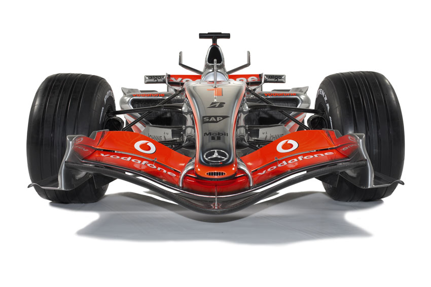
Noses i feel will look like this on the MP4/22:

Image
Image

However there will be a 2014 front wing and 2014 style 'walrus' style supports.

astracrazy
astracrazy
31
Joined: 04 Mar 2009, 16:04

Re: 2014 Design

Post

i know about the nose just couldn't remember if the tub was being lowered or now

cheers

ESPImperium
ESPImperium
64
Joined: 06 Apr 2008, 00:08
Location: Glasgow, Scotland

Re: 2014 Design

Post

The rumor is that the A-A line in 2015 will be lowered to 600mm for field of vision reasons. However with the 2016 rules posibly seeing wheels going to 16" diamater, the chassis will have to be at least 610mm there, so id suggest that 610mm will be adopted.

But thats in the future, 2014 is 625mm, with engineers saying that some of the noses will look ugly. Maybes a return to 2012 noses, but i doubt that.