Matt Somers wrote:@WPTFormula asked me to stop by and have a look at this and I have to applaud the thinking @turbof1, I must say I did have similar thoughts when I first drew a Walrus style nose.
Yeah thanks! I was looking at a different design (the one posted in the ferrari speculation topic), where they did something odd with the nose. I was thinking about how that could have been made legal, and then suddenly the assymetrical idea jumped on me. Then I took a look on the rule and suprisingly nothing is widstanding this.
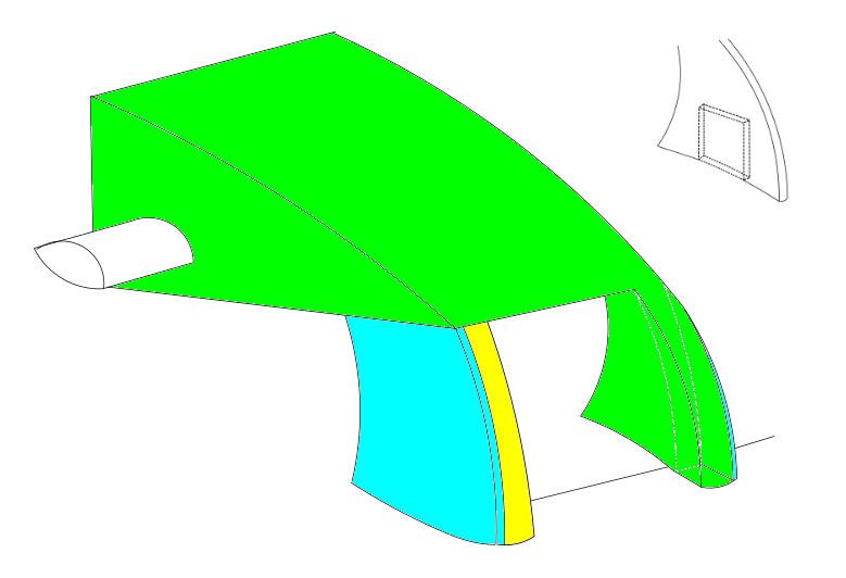
Firstly the nose tip that's adjoined to one side of the Y250 would create an inconsistent airflow pattern to that of the other side (unless of course you designed the nose tip to fit inside the pylon

)
I was thinking about using the vanity panel to mirror the nose to the other side. And yes, you could place the pylons behind the "teeth" and use them to smoothen out sharp edges.
I'm quite sure a clarification would quickly ensue from Charlie if anyone did try to run such a design as it would mean a complete rethink/redesign from everyone...
Yes, unfortunaly. It's quite an unsafe design; charley, and if not him the FIA, would do anything to get rid of it. I do feel though that other extreme designs like the "snowplough" nose will get the same fate.
Anyway, as a theoritical excercise I really enjoyed this.