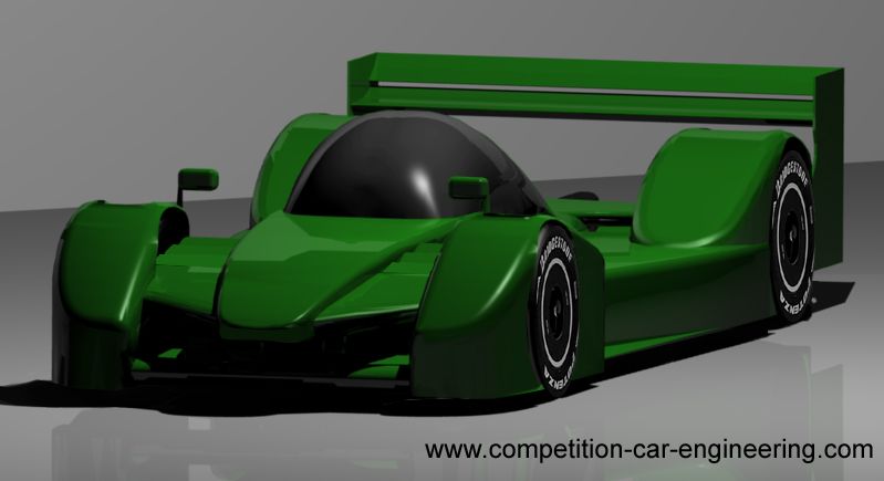
[KVRC ~ish] CCE LMP01

Post here information about your own engineering projects, including but not limited to building your own car or designing a virtual car through CAD.
User avatar
machin
162
Joined: 25 Nov 2008, 14:45

[KVRC ~ish] CCE LMP01

Post

Well all of these cars being released for the KVRC has inspired me to have a quick go and knocking one up myself, and hopefully inspire others to do likewise...

I'm going to do this without resorting to CFD analysis, using empirical data to show how it could be done if you don't have the time (or inclination) to learn and use CFD, and yet still get some rough estimates for aerodynamic coefficients. Many successful racing cars have been designed this way prior to the advent of CFD, and indeed it happens today in amateur motorsport... plus I think it is good to understand how the maths works rather than just expecting the answer from a computer.

I just want to make it clear that the car below is not specifically compliant with the KVRC regulations, or indeed the LMP1 regs themselves; it is the process that I was interested in, and the process itself could be applied to a KVRC compliant design. So whilst it looks like a KVRC car, please don't pick me up on non-compliant parts!

The first thing is to set out the "fixed points", all those things that you have no or little scope to change: Generally this might be the driver position, powertrain and the wheels/tyres. I've also added in a full tub and heat exchangers. (For the KVRC the tub, suspension powertrain and tyres are all available to download).
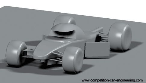
Image

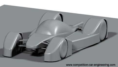
The next step is to start "clothing" those parts in aerodynamic fairings. At this point in time I'm not really thinking about downforce, just trying to provide a smooth path around these objects from front to rear; trying to avoid particularly sharp edges near the front. This should mean that when I come to design a low downforce design I have a nice low-drag base on which to work from.

First up are the wheel fairings. I've used a similar design at the front as at the rear.. I've done this because I know these fairings will likely produce some lift; by keeping them similar front to rear I should minimise the effect these parts have on the aerodynamic balance (front to rear downforce/lift).
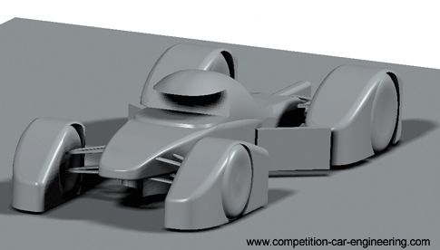
Image

I take a similar approach with the side pods and canopy: nice and smooth with no sharp edges where I can avoid it:-
Image

At this point I'm going to estimate the base car's lift and Drag... frontal area is about 1.6m^2. Because the shape is quite smooth, with no drag inducing elements yet, I'm going to estimate that the drag coefficient is about 0.55... hopefully that is a bit pessimisstic (a typical family car is around 0.3 these days, a Caterham 7 is about 0.65). I suspect that it generates some lift, so I'll say that is around 0.1 (upwards). So my starting coefficients, after multiplying by the frontal area, are going to be somewhere in the region of:-

Cd.A = 0.88
Cl.A = 0.16

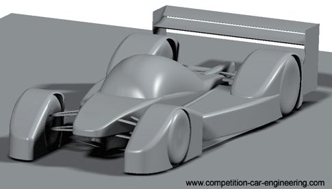
Next I will add a rear wing. Generally the rules for rear wings are that they are quite prescriptive; generally limiting the number of elements and the overall width, length and height that these elements can fit in. To design the rear wing I will use data from the North American Advisory Committee for Aeronautics; hundreds of reports can be obtained from their weibsite giving you access to a huge range of wing data. Here's a link to one such example: http://ntrs.nasa.gov/archive/nasa/casi. ... 090976.pdf

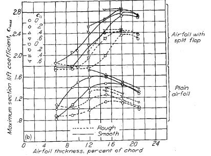
...Where you will find a whole heap of charts like this one from which you can obtain wing coefficients:
Image

I've selected a twin element NACA 4415 wing. The great thing about the NACA data is it tells you exactly the shape of aerofoil you need, slots gaps, and sizing of the flap relative to the main element. Because the first round of the KVRC is a high downforce round I need to get as much downforce as possible (see the Virtual Stopwatch lap time estimation tool: HERE), so I've set the Width, Chord and angle of attack of the wing assembly so it fills the allowable box as much as possible.

Looking at the data I see that this two element 4415 wing arrangement at my angle of attack results in a Cl of about -2.75 and a Cd. of 1.0. Now one point to remember is that wing coefficients generally work on the plan area, not the frontal area as for cars. In my case the plan area of the wing is 0.8m^2 and therefore the wing's total Cl.A would be 2.2m^2 and its Cd.A 0.8m^2.
Image

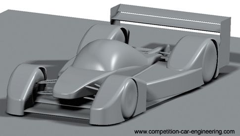
Now, the downforce at the front of my car needs to balance the rear. Because the mass balance of the car is slightly rearward (45:55 front:rear), my front downforce needs to be about 19% less than at the rear. Before I add my front downforce producing elements though I'm going to consider my diffuser. Most categories are again quite prescriptive in the allowance for diffsuers unless you can find a loop hole (as with F1's 2009 "Double diffuser" affair), so I'll just maximise the diffuser as much as I can within the rules. Data on diffuser downforce is quite rare, but we know in F1 that about 1/3 of the total car's downforce comes from the underfloor, and due to the position of the diffuser "kink line" this downforce is going to be nearer the rear of the car than the front, so I'm going to estimate that the front end of the car needs to balance all of the downforce from the two element rear wing, despite the mass distribution.

Again I turn to the NACA data and decide to fit a two element wing. For simplicity I'll use two 4415 section elements again (simply because I've already modeled them and can just copy the model!), but this time the flap angle will be slightly less to fit under the front suspension. The Cl. of this set-up I've chosen is again read off the NACA data, and turns out to be 2.0, so I'm going to need more area than the rear wing. To find the area I need I simply divide the Cl.A of the rear wing by the Cl. of the front wing (2.2 / 2 ) which turns out to be 1.1m^2). These elements, being positioned between the front wheels and in close proximity to the tub will lose some efficiency due to dirty air, but in their favour they are working in ground effect, so I'm going to assume that these two issues cancel each other out. The Cd of the front wing arrangement is about 0.6 (again, read off the NACA data tables), so the Cd.A is about 0.66 (the lower flap angle is a little more efficient in this case than the rear, hence lower drag). (EDIT: I might be tempted to increase the area slightly over the calculated 1.1m^2 because lap time simulation shows there is not much penalty for doing so)

Because we've multiplied the Cl and Cd wing values by the plan area we now have Cl.A and Cd.A values that can be directly added to the Cl.A and Cd.A values for the main part of the car itself, even though that part was worked out on its frontal area.

Main Body Cd.A = 0.88 Cl.A = 0.16
Rear Wing Cd.A = 0.8 Cl.A = -2.2 (note I've written the sign as negative here to differentiate from the main body lift)
Front Wing Cd.A = 0.66 Cl.A = -2.2
Underbody Cd.A = 0 Cl.A = -2.2 (underbody assumed to be about 33% of the total downforce, with no drag)

TOTAL Cd.A = 2.34 Cl.A = -6.44 COP ~ 1.65m
Image

Now I need to add all those elements that are required to make the car fit within the rules: wing mirrors, Suspension covers, etc. I add these parts in a way that I think will be not too detrimental to overall performance; i.e. trying to keep them aligned with what I think will be the local flow direction, and keeping these parts as smooth as possible. Even so I'm going to assume that these minor parts reduce my overall efficiency somewhat; increasing drag and reducing downforce, but hopefully not affecting balance too much.

Revised overall Coefficient estimates: Cd.A = 2.5 Cl.A = 6.2 (COP still ~1.65m)

And I have my "finished" car ready for submission to KVRC or whatever championship I'm intending to use the car in.
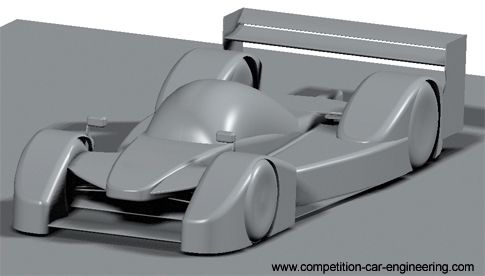
Image

The next installment of this mini-blog will come after the first round when all competitors will have received aero coefficients generated from their submitted cars by the KHAMSIN CFD program used by the KVRC organisors.

I hope that this little write up helps to inspire others to enter the KVRC, or even just to have a go themselves, and not to worry if they don't have CFD capability themselves. The car in these images was started from scratch and only took a few hours to make this afternoon (I already had the suspension and tyres from a previous model though), so there is still time to make a car.

Link to the KVRC main thread: HERE.
COMPETITION CAR ENGINEERING -Home of VIRTUAL STOPWATCH

User avatar
CAEdevice
49
Joined: 09 Jan 2014, 15:33
Location: Erba, Italy

Re: [KVRC ~ish] CCE LMP01

Post

Inspiring approach! I could learn very much reading this, thanks a lot.
I hope it could inspire new partecipants.

PS: The numbers are very reasonable

User avatar
machin
162
Joined: 25 Nov 2008, 14:45

Re: [KVRC ~ish] CCE LMP01

Post

Continuing from where I left off, as promised now that everyone in the KVRC championship has official CFD figures I'm going to run through the process I would use to improve my car, without resorting to my your own CFD.

From the official results you know how your car performed and it is likely that you have some aerodynamic imbalance.
Basically this imbalance means that one end of your car is making unnecessary drag since the the other end of the car doesn't make enough downforce to allow that end of the car to corner at the same speed as the one with more downforce...
So you have two options:

Increase downforce at the deficient end, or decrease downforce at the high end. For the high downforce rounds you ideally would bring up the deficient end, and you need to try and achieve a downforce split which matches the mass balance, so:

If your front downforce is highest:-
(Clf.A) x (55/45) = ideal Clr.A

If your rear downforce is highest:-
(Clr.A)x(45/55) = ideal Front Clr.A

Your Clf.A and Clr.A can be read off my chart on the KVRC thread: http://twitter.com/Comp_Car_Eng/status/ ... 6535191552 Now take your ideal Clf.A or Clr.A and subtract your actual Clf.A or Clr.A

(ideal Clf.A) - (actual Clf.A) = Additional Clf.A required.

This is what you need to add to your car.

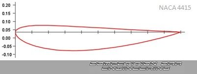
Now in my case I need to find an additional 0.5 Cl.A at the front of my car. So I'm going to turn to my trusty NACA 4415 section element, which has the following shape:-

Image

And reading off the NACA data this element has a Cl of 1.3 at 10 degrees. So I would need an additional NACA aerofoil at 10 degrees with a plan area of 0.38m^2 (0.5/1.3 = 0.38) in order to balance my car.

One point which I maybe didn't make too clear before was that when you use these NACA aerofoils, you need to make sure that the shape is scaled properly, and not "stretched". The image below shows what I mean, where the long but narrow front elements are considerably "thicker" than the short but wide elements used in the rear wing.

Image

You can see that I have chosen to fit my additional elements onto an extended version of the nose above the existing two elements, and I have replaced the original covers over the suspension with a series of louvres to hide the suspension from above whilst (hopefully!) not disturbing the air flow too much from the new upper element....

So you should now have a balanced car, and by adding your new Cl.A to your official results Cl.A you can estimate your new Overall Cl.A, but now you should have COP=1.65m.

You can also estimate your new Cd.A using the NACA data. My 10 degree NACA 4415 profile has a drag coefficient of 0.25, multiplied by the additional new area of 0.38m^2 means an additional Cd.A of 0.096m^2, which is added to the official CFD results to estimate your new overall Cd.A.

Image

In the next step I will look at how I would use my rival's cars to improve my own car even more.
COMPETITION CAR ENGINEERING -Home of VIRTUAL STOPWATCH

MadMatt
MadMatt
125
Joined: 08 Jan 2011, 16:04

Re: [KVRC ~ish] CCE LMP01

Post

Machin, fantastic work! Great job at your writing, I really like this academical way of thinking!

Plus your car looks awesome, keep up the good work! :D

People that are new to the aero world raed this thread, plenty of good things to take!

User avatar
RicME85
52
Joined: 09 Feb 2012, 13:11
Location: Derby

Re: [KVRC ~ish] CCE LMP01

Post

Is that NACA profile worth using?
Over the years with KVRC I have looked into loads of NACA profiles but never know which route to go down.

MadMatt
MadMatt
125
Joined: 08 Jan 2011, 16:04

Re: [KVRC ~ish] CCE LMP01

Post

It depends a lot of things, but if you check google for "high lift airfoils" it will give you good basic ones that you can investigate. If you want to try that, use JavaFoil (free web app). There you can either quickly simulate 2D NACA profiles, or custom profiles using coordinates. I had good success using Eppler profiles in the past, but there are other good ones as well!

I usually use NACA profiles for low drag airfoils.

User avatar
machin
162
Joined: 25 Nov 2008, 14:45

Re: [KVRC ~ish] CCE LMP01

Post

Machin, fantastic work! Great job at your writing, I really like this academical way of thinking
Thanks Matt. I think CFD is great... But I don't think it helps with the initial design... In fact, it could be detrimental to initial design... A good empirically based starting point... With later refinement in CFD if that is available to you... Will lead to the best performance in the shortest possible time, in my opinion...

Yeah, you can definitely get more downforce from a more highly cambered aerofoil profile... With more drag of course...

However.... I think a 4415 is infinitely better than a guessed profile... If for no other reason than you can at least use empirical data to estimate your performance (as above)... If you draw something that is vaguely "aerofoil shaped" there is a good chance you could guess wrong and have something which doesn't work at all....

Personally I'd say the 4415 is a good starting point....
COMPETITION CAR ENGINEERING -Home of VIRTUAL STOPWATCH

User avatar
CAEdevice
49
Joined: 09 Jan 2014, 15:33
Location: Erba, Italy

Re: [KVRC ~ish] CCE LMP01

Post

Hi Machin, I'm not used to aero coefficients, could you convert the Cl.A of the rear wing in force (N)?

User avatar
AratzH
9
Joined: 07 May 2013, 09:24
Location: Michigan

Re: [KVRC ~ish] CCE LMP01

Post

If Cl.A=Cl x S(platform area), then downforce = Cl.A x rho(air density) x V^2(velocity squared)

By the way comgrats to everybody, specially the top three. I hope to have ,y car a little clpser next rpund :p
MVRC -> TF

User avatar
CAEdevice
49
Joined: 09 Jan 2014, 15:33
Location: Erba, Italy

Re: [KVRC ~ish] CCE LMP01

Post

Thank you AratzH, so, let's try with the rear wing:

Rw Cl.A = 2.2 m2
DF of teh rear wing = (2.2 m2) * (1.2 kg/m3) * (44.7 *44.7 m2/s2) = 5274 N ??? What I did wrong?

User avatar
AratzH
9
Joined: 07 May 2013, 09:24
Location: Michigan

Re: [KVRC ~ish] CCE LMP01

Post

The only thing I can think of is an error in the Cl.A calculation. I think thak the Cl that appears in the NACA plots is not so but cl instead (coefficient of lift per section).
The problem is that cl == Cl only for wings of infinite length. Due to the wingtip vortices that are created in a real wing, the Cl is usually lower than cl.
MVRC -> TF

User avatar
CAEdevice
49
Joined: 09 Jan 2014, 15:33
Location: Erba, Italy

Re: [KVRC ~ish] CCE LMP01

Post

AratzH wrote:The only thing I can think of is an error in the Cl.A calculation. I think thak the Cl that appears in the NACA plots is not so but cl instead (coefficient of lift per section).
The problem is that cl == Cl only for wings of infinite length. Due to the wingtip vortices that are created in a real wing, the Cl is usually lower than cl.
Yes, I think so.

I'm expecting a DF value like 200-2000N from the rear wing.

User avatar
machin
162
Joined: 25 Nov 2008, 14:45

Re: [KVRC ~ish] CCE LMP01

Post

Remember that my car isn't designed to the specific KVRC regs... so my Cl.A of 2.2 was based on my wing dimensions which may or may not be comparable to the KVRC regs... I think the Cl of the dual element wing in my model was 2.7, so I had worked on a 0.8m^2 wing area... I guess you have slightly less in the KVRC?

But indeed it is correct that the NACA data is for a slender wing without the wing tip vortex effect. That's where a good design of wing endplate is needed! The data gives you the "ideal" result with free-stream air; you need to modify the result to take account of things like non-ideal conditions, interaction with other nearby objects etc.

You can minimise the effects by designing your car accordingly.. the Dyna Race car and Variante's cars for example are good in this respect: both front and rear wings are as far away from the body as possible, thereby reducing the interaction effects.... My front underwing isn't ideally positioned between the wheel fairings and nose cone, which is why I reduced the predicted performance down somewhat...
COMPETITION CAR ENGINEERING -Home of VIRTUAL STOPWATCH

User avatar
CAEdevice
49
Joined: 09 Jan 2014, 15:33
Location: Erba, Italy

Re: [KVRC ~ish] CCE LMP01

Post

machin wrote:so my Cl.A of 2.2 was based on my wing dimensions which may or may not be comparable to the KVRC regs... I think the Cl of the dual element wing in my model was 2.7, so I had worked on a 0.8m^2 wing area... I guess you have slightly less in the KVRC?
OK, I think that the KVRC area of the rear wing is about 0,5m2 (2m x 0.25m).

User avatar
machin
162
Joined: 25 Nov 2008, 14:45

Re: [KVRC ~ish] CCE LMP01

Post

Well that explains it then... and why I overestimated Variante's overall Cl before the numbers were revealed!!!

:D
COMPETITION CAR ENGINEERING -Home of VIRTUAL STOPWATCH