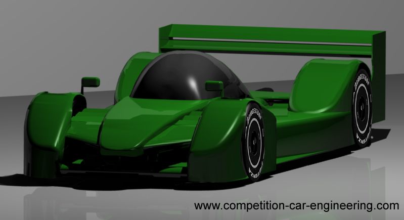
I'm going to do this without resorting to CFD analysis, using empirical data to show how it could be done if you don't have the time (or inclination) to learn and use CFD, and yet still get some rough estimates for aerodynamic coefficients. Many successful racing cars have been designed this way prior to the advent of CFD, and indeed it happens today in amateur motorsport... plus I think it is good to understand how the maths works rather than just expecting the answer from a computer.
I just want to make it clear that the car below is not specifically compliant with the KVRC regulations, or indeed the LMP1 regs themselves; it is the process that I was interested in, and the process itself could be applied to a KVRC compliant design. So whilst it looks like a KVRC car, please don't pick me up on non-compliant parts!
The first thing is to set out the "fixed points", all those things that you have no or little scope to change: Generally this might be the driver position, powertrain and the wheels/tyres. I've also added in a full tub and heat exchangers. (For the KVRC the tub, suspension powertrain and tyres are all available to download).
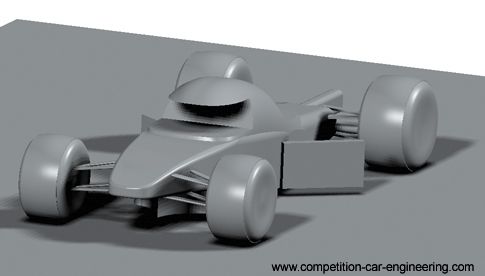
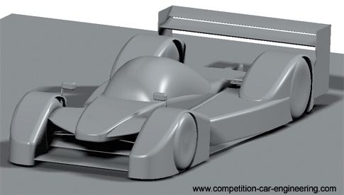
The next step is to start "clothing" those parts in aerodynamic fairings. At this point in time I'm not really thinking about downforce, just trying to provide a smooth path around these objects from front to rear; trying to avoid particularly sharp edges near the front. This should mean that when I come to design a low downforce design I have a nice low-drag base on which to work from.
First up are the wheel fairings. I've used a similar design at the front as at the rear.. I've done this because I know these fairings will likely produce some lift; by keeping them similar front to rear I should minimise the effect these parts have on the aerodynamic balance (front to rear downforce/lift).
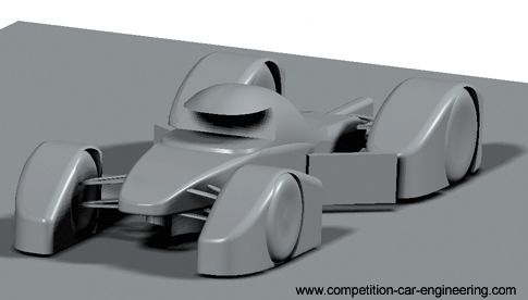
I take a similar approach with the side pods and canopy: nice and smooth with no sharp edges where I can avoid it:-
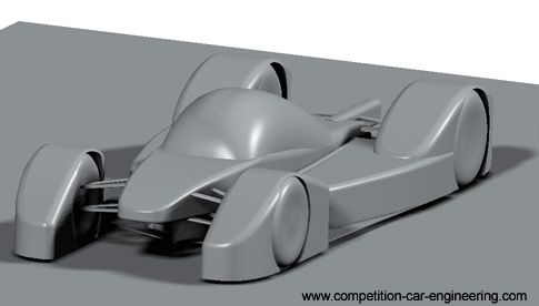
At this point I'm going to estimate the base car's lift and Drag... frontal area is about 1.6m^2. Because the shape is quite smooth, with no drag inducing elements yet, I'm going to estimate that the drag coefficient is about 0.55... hopefully that is a bit pessimisstic (a typical family car is around 0.3 these days, a Caterham 7 is about 0.65). I suspect that it generates some lift, so I'll say that is around 0.1 (upwards). So my starting coefficients, after multiplying by the frontal area, are going to be somewhere in the region of:-
Cd.A = 0.88
Cl.A = 0.16
Next I will add a rear wing. Generally the rules for rear wings are that they are quite prescriptive; generally limiting the number of elements and the overall width, length and height that these elements can fit in. To design the rear wing I will use data from the North American Advisory Committee for Aeronautics; hundreds of reports can be obtained from their weibsite giving you access to a huge range of wing data. Here's a link to one such example: http://ntrs.nasa.gov/archive/nasa/casi. ... 090976.pdf
...Where you will find a whole heap of charts like this one from which you can obtain wing coefficients:
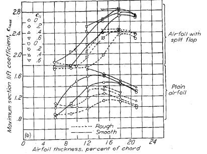
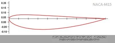
I've selected a twin element NACA 4415 wing. The great thing about the NACA data is it tells you exactly the shape of aerofoil you need, slots gaps, and sizing of the flap relative to the main element. Because the first round of the KVRC is a high downforce round I need to get as much downforce as possible (see the Virtual Stopwatch lap time estimation tool: HERE), so I've set the Width, Chord and angle of attack of the wing assembly so it fills the allowable box as much as possible.
Looking at the data I see that this two element 4415 wing arrangement at my angle of attack results in a Cl of about -2.75 and a Cd. of 1.0. Now one point to remember is that wing coefficients generally work on the plan area, not the frontal area as for cars. In my case the plan area of the wing is 0.8m^2 and therefore the wing's total Cl.A would be 2.2m^2 and its Cd.A 0.8m^2.
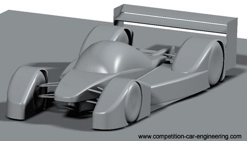
Now, the downforce at the front of my car needs to balance the rear. Because the mass balance of the car is slightly rearward (45:55 front:rear), my front downforce needs to be about 19% less than at the rear. Before I add my front downforce producing elements though I'm going to consider my diffuser. Most categories are again quite prescriptive in the allowance for diffsuers unless you can find a loop hole (as with F1's 2009 "Double diffuser" affair), so I'll just maximise the diffuser as much as I can within the rules. Data on diffuser downforce is quite rare, but we know in F1 that about 1/3 of the total car's downforce comes from the underfloor, and due to the position of the diffuser "kink line" this downforce is going to be nearer the rear of the car than the front, so I'm going to estimate that the front end of the car needs to balance all of the downforce from the two element rear wing, despite the mass distribution.
Again I turn to the NACA data and decide to fit a two element wing. For simplicity I'll use two 4415 section elements again (simply because I've already modeled them and can just copy the model!), but this time the flap angle will be slightly less to fit under the front suspension. The Cl. of this set-up I've chosen is again read off the NACA data, and turns out to be 2.0, so I'm going to need more area than the rear wing. To find the area I need I simply divide the Cl.A of the rear wing by the Cl. of the front wing (2.2 / 2 ) which turns out to be 1.1m^2). These elements, being positioned between the front wheels and in close proximity to the tub will lose some efficiency due to dirty air, but in their favour they are working in ground effect, so I'm going to assume that these two issues cancel each other out. The Cd of the front wing arrangement is about 0.6 (again, read off the NACA data tables), so the Cd.A is about 0.66 (the lower flap angle is a little more efficient in this case than the rear, hence lower drag). (EDIT: I might be tempted to increase the area slightly over the calculated 1.1m^2 because lap time simulation shows there is not much penalty for doing so)
Because we've multiplied the Cl and Cd wing values by the plan area we now have Cl.A and Cd.A values that can be directly added to the Cl.A and Cd.A values for the main part of the car itself, even though that part was worked out on its frontal area.
Main Body Cd.A = 0.88 Cl.A = 0.16
Rear Wing Cd.A = 0.8 Cl.A = -2.2 (note I've written the sign as negative here to differentiate from the main body lift)
Front Wing Cd.A = 0.66 Cl.A = -2.2
Underbody Cd.A = 0 Cl.A = -2.2 (underbody assumed to be about 33% of the total downforce, with no drag)
TOTAL Cd.A = 2.34 Cl.A = -6.44 COP ~ 1.65m
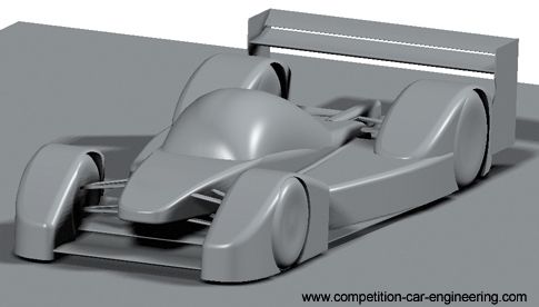
Now I need to add all those elements that are required to make the car fit within the rules: wing mirrors, Suspension covers, etc. I add these parts in a way that I think will be not too detrimental to overall performance; i.e. trying to keep them aligned with what I think will be the local flow direction, and keeping these parts as smooth as possible. Even so I'm going to assume that these minor parts reduce my overall efficiency somewhat; increasing drag and reducing downforce, but hopefully not affecting balance too much.
Revised overall Coefficient estimates: Cd.A = 2.5 Cl.A = 6.2 (COP still ~1.65m)
And I have my "finished" car ready for submission to KVRC or whatever championship I'm intending to use the car in.
The next installment of this mini-blog will come after the first round when all competitors will have received aero coefficients generated from their submitted cars by the KHAMSIN CFD program used by the KVRC organisors.
I hope that this little write up helps to inspire others to enter the KVRC, or even just to have a go themselves, and not to worry if they don't have CFD capability themselves. The car in these images was started from scratch and only took a few hours to make this afternoon (I already had the suspension and tyres from a previous model though), so there is still time to make a car.
Link to the KVRC main thread: HERE.

