manolis wrote:Hello Muniix
You write:
“Yes but your sealing array is totally different, experiences totally different forces and is three dimensional whereas the RX-8 is just apex and side seals.
The forces that need to be dealt with are the thrust forces the seals see from combustion pressure, one needs to dynamically adapt to these forces that are trying to seperate the seal from the surface they are abuting to. As pressure rises it will force this seal to collapse, one needs to compensate for this force, while not providing excessive force as to create to much friction whan not needed. This is typically done with gas ports, that allow the cylinder pressure to get behind the seals, this acts like a capacitor, it also has to deal with the sliding friction of the working surface the seals are sliding against, so the pressure between the seal and its slot surfaces needs to be carefully balanced to avoid the seal being forced against one slot face and creating too much friction with that face. A spring behind the seal needs to provide just enough tension to support the minimun sealing force and cover for the period before the gas force is used to assist the sealing force.”
It seems you didn’t yet got the mechanism according which the seals in the PatWankel work.
Start with the top ring in the piston of a reciprocating piston engine.
It is made to have a slight preloading to keep its external (or better: working) surface in touch with the cylinder liner.
The pressure in the combustion chamber of the reciprocating engine arrives into the groove of the seal and pushes it towards the cylinder liner and towards the bottom of its groove.
What is so important with it?
The pressure ring abuts heavily onto the cylinder liner only during the high pressure period of the cycle, achieving the necessary sealing at low friction loss.
Think of a bicycle pump, that with the leather seal. During the compression the leather seal is pushed towards the cylinder wall and achieves the required sealing. During the suction of fresh air, the seal adds no friction.
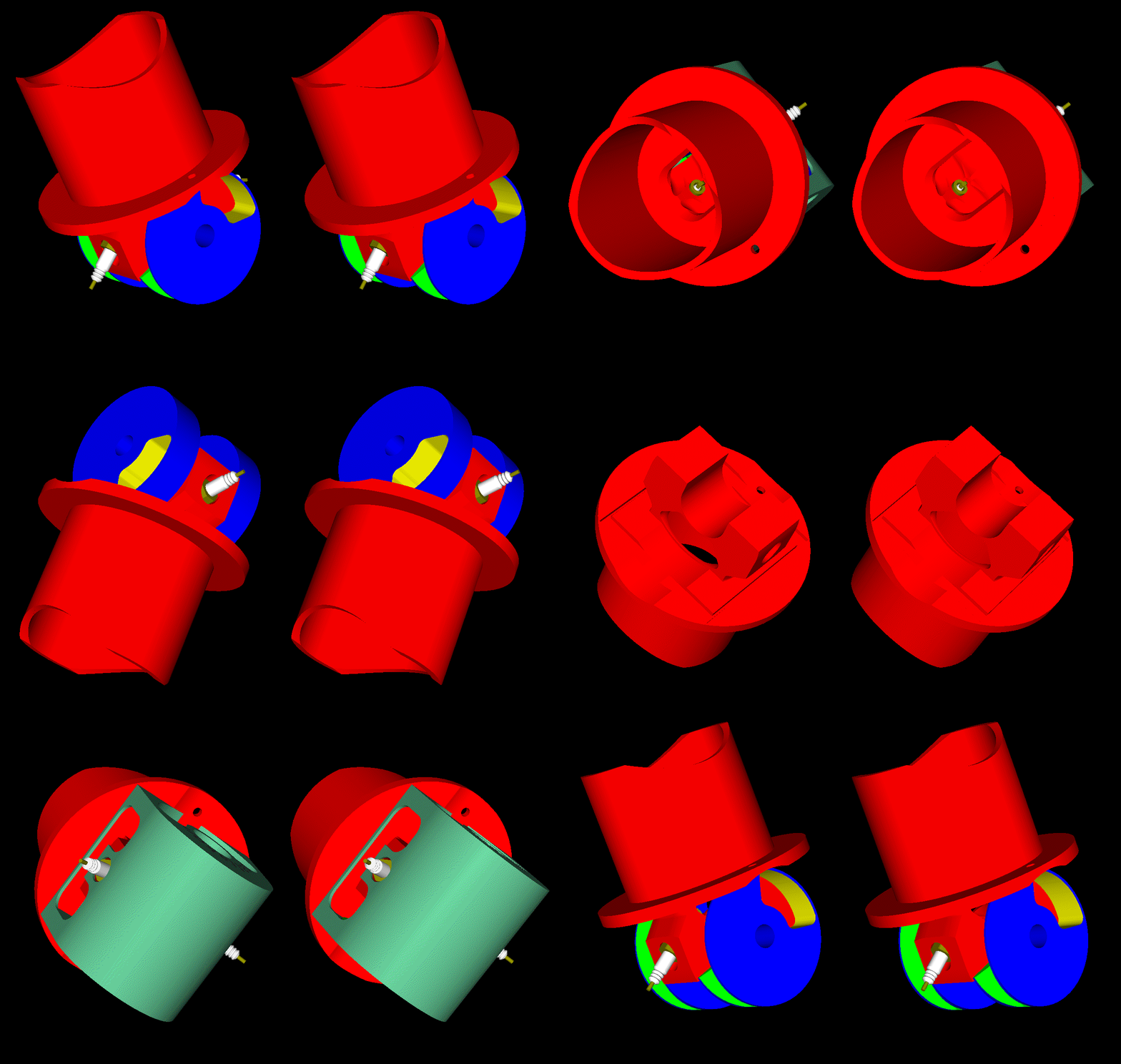
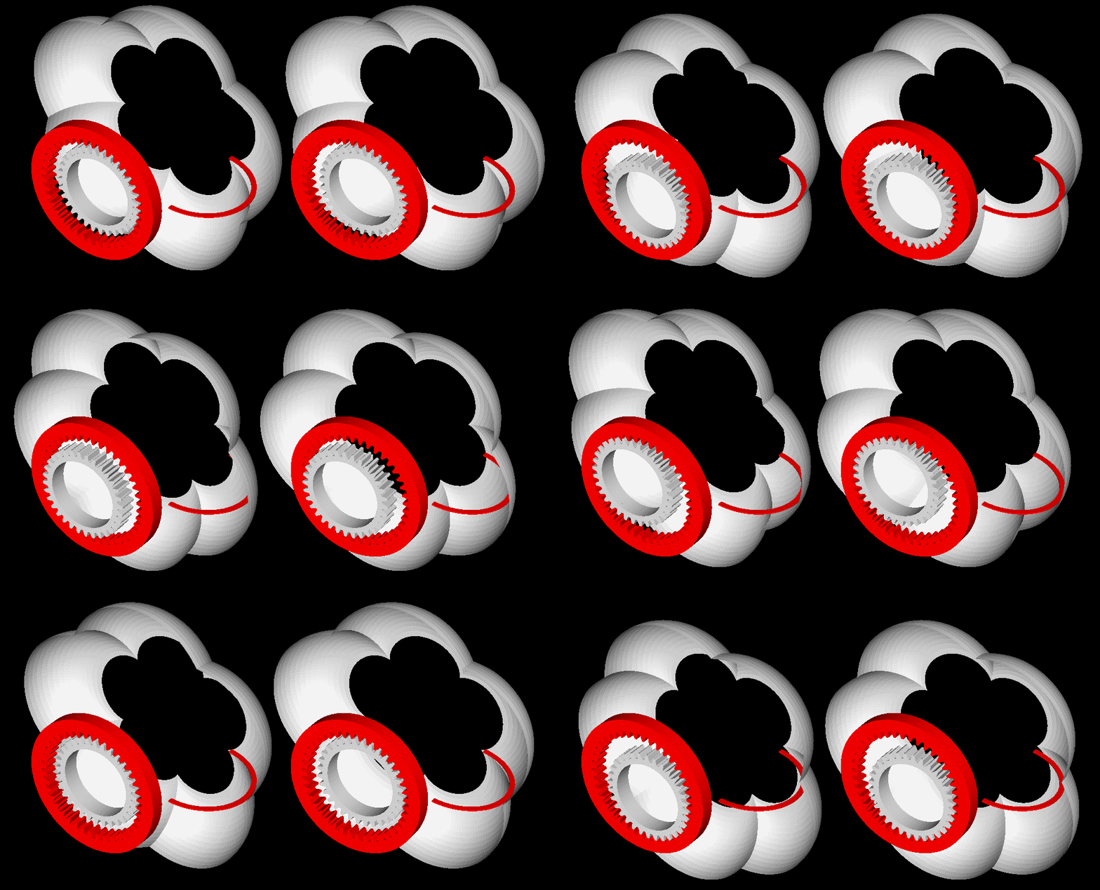
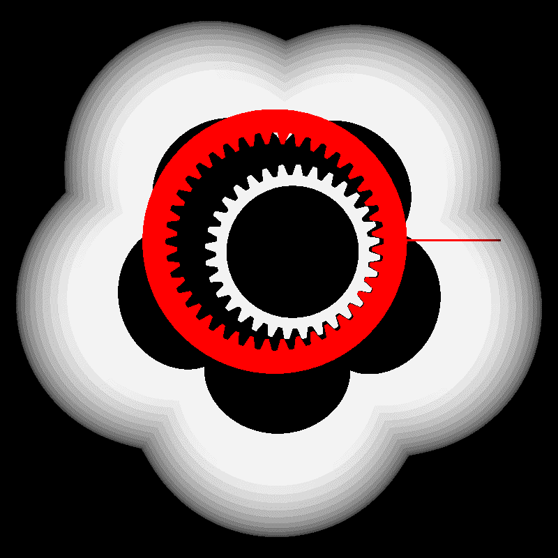
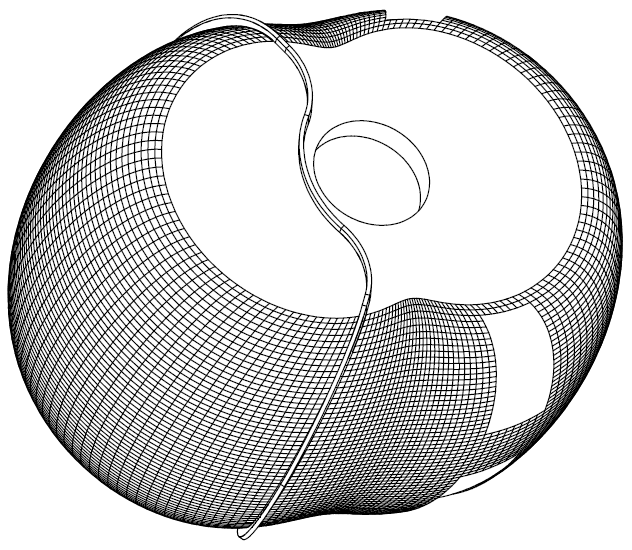
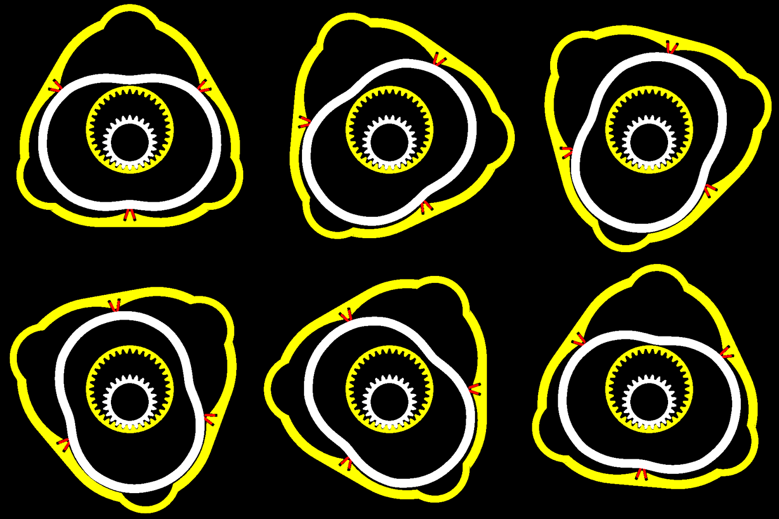
The difference of the PatWankel seals as compared to the reciprocating piston rings is that, depending on the version, the “working “ surface is either the “external surface” of the seal, or the “inner surface” of the seal (version with the working surface on the inner body) like:
http://www.pattakon.com/PatWankel/PatWankel_iGR_16.gif
wherein each seal and each groove serve one only working chamber, the working surface (whereon the seals abut and slide) is the external surface of the inner body:
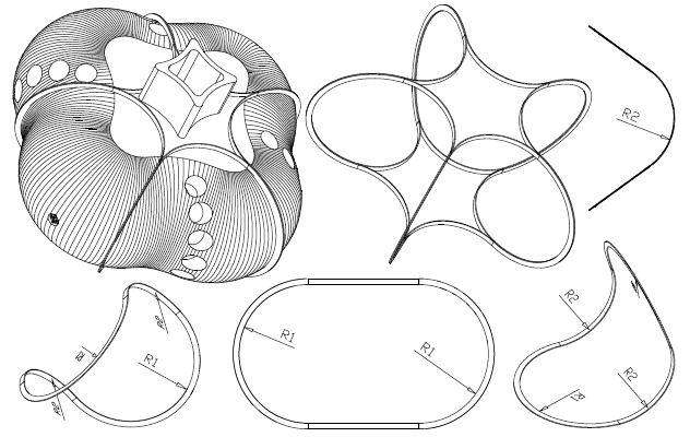
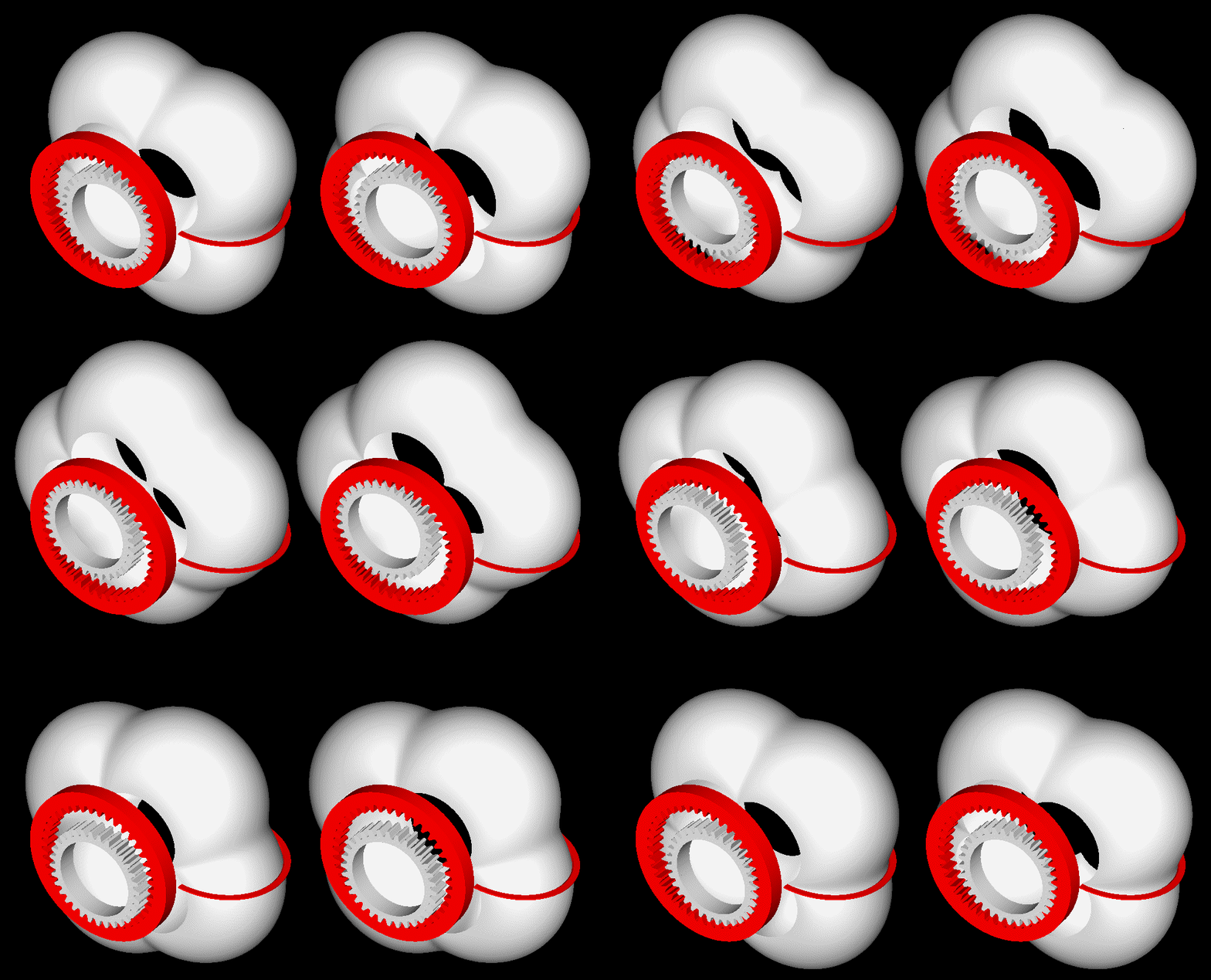
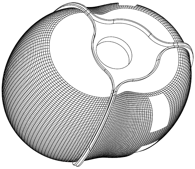
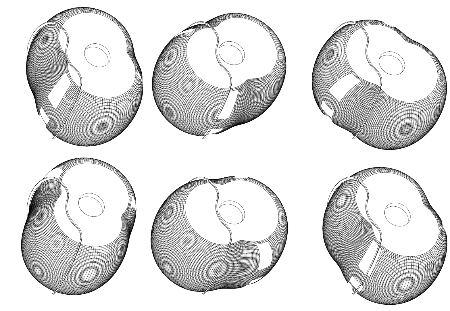
Here is the inner body alone, with the three seals on it:
http://www.pattakon.com/PatWankel/PatWankel_iGR_16A.gif
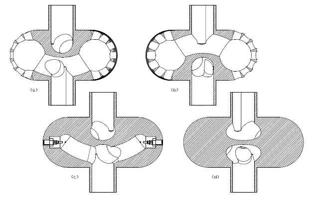
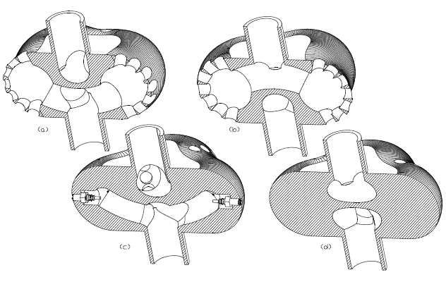
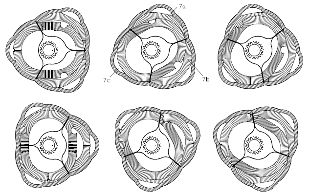
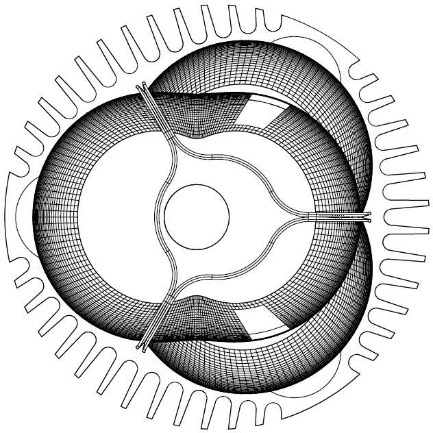
In the following drawing the two, of the three, seals have been removed.
http://www.pattakon.com/PatWankel/PatWankel_iGR_16B.gif
The working chamber at left is at its TDC with its seal surrounding it and sealing it.
The inner body is like a "piston" pushed deaply into the working chamber (an unconventional piston that needs neither a connecting rod, nor a crankshaft).
As the inner and outer bodies (which comprise the engine) rotate, the "piston" (i.e. the inner body), remaining permanently in contact with the seals, is pushed outwards from the chamber and the volume increases (expansion).
The “sealing” principle is the same with the reciprocating piston engines: the pressure in the working chamber is also the pressure inside the groove of the seal. This pressure, during the high pressure period of the cycle, forces the seal towards the “working surface” (and towards the “bottom” of the groove, just like in the reciprocating engines) and seals the working chamber.
Look again at the above drawing.
Ok, when you say "bottom" you don't mean underside, as the pressure would be pushing it away from the underside and against the far-side edge, away from the combustion origin. So "Bottom" is not the best description, Maybe standardising on Under, Inner and Outer seal edges may be more descriptive. Consistancy is important, also a glossary one can refer to. Just a thought.
Each working chamber has its own / exclusive seal and its own / discrete groove wherein the seal is mounted.
Doubling up on sealing will increase the total seal area, negatively effecting friction mean effective pressure FMEP.
One will need to keep a total frictional area per chamber, manufactured in tension into the seals may not provide sufficient sealing force on its own, nearly guaranteed there will be areas where gas will leak from insuficient seal force, the dynamic nature of the environment means achieving optimal sealing force over the whole length of the seal from tension alone will be highy improbable. Additional force will likely be needed. Combustion CFD will reveal this pretty quickly, as will a pressure sensor revealing the loss of cylinder pressure, you will need to identify how you are going to measure cylinder pressure and seal force pressures to 'tune' and 'optimise' the engine, surface acoustic wave sensors to measure seal force under the seals, these can be made wireless, a friend of mine worked on developing these in Ryde decades ago at the AWA Microelectronics Fabrication facility, just up the road from Bishop, SAW = sensors on a silicon substrate.
Providing sufficient force to survive the delay time it takes for the gas to provide the counter force to maintain a effective seal, the gas force seal pressure assistance is like a capacitor it takes time to charge up and to discharge. One needs to maintain some charge in it at all times to all surface areas. A solution will need to be found for this issue, springs, polymers, the environment is slightly hostile to say the least down under the seal and between its groove, without blocking the gas itself which is needed to apply some force to the far side seal edge, to reduce the pressure on that edge else the seal will stay stuck against the far edge. This is compounded by the rotational frictional force.
There are also issues with the gaps between seals in the same groove, and the pressure between seals of adjacent cylinders. This area will hold blow-by from all chambers, maybe colouring it in a different colour to highlight blow-by areas/potential crevice volumes.
Otherwise it is on its way to a solution for the rotary engine, brings its own new set of issues, which a small team of dedicated talented people have been known to solve given enough resources and the tools to measure all properties they are dealing with.
Their is nothing funnier than watching someone dyno their engine and seeing torque rapidly drop off as engine speed increases, without high speed cylinder pressure sensors to indicate exhaust pressure isn't being blown down fast enough before bdc!!
The left side of the inner body shown in the drawing is at the TDC.
The left seal surrounds the one working chamber and abuts on the working surface on the inner body, just like a piston ring abuts on the cylinder liner.
The pressure at the left side of the groove wherein the left seal is inside (not shown in the drawing) equals to the pressure into the “left” working chamber. This pressure, just like in the reciprocating piston engines, presses the seal to abut on the inner body and onto the right side (i.e. the bottom) of its groove.
Bottom = Far side (outside edge away from compression origin) and away from the seals underside?
Remembering that piston rings have built in tension to provide initial sealing force around a perfectly round piston, this is a nice simple environment for this scheme to work. Your environment is very different it is 3d with infinetly different angles, not the perfect environment for preset tension to provide the initial seal force. Additionally it is a very large sealing area, with differing pressures and temperatures along the seal as each part of the seal will be a different distance from the origin of combustion, so local speed of sound issues for the acoustic energy to have effect on the pressures waves arriving at the seals exposed surfaces.
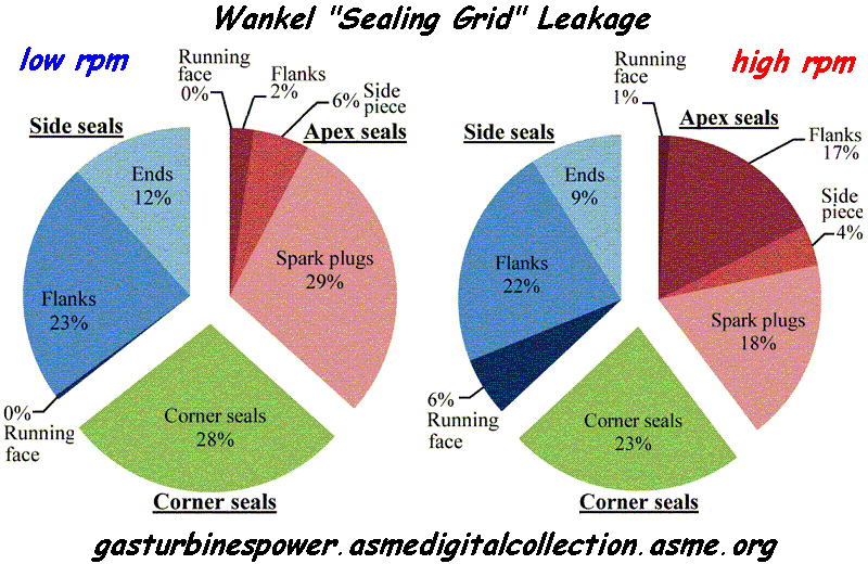
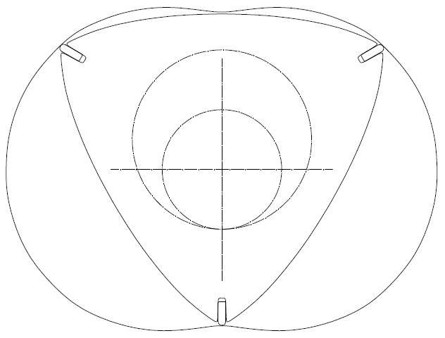
Now, look again at the pie-plot of ASME and think the reduction of the gas leakage in a rotary engine (and the friction reduction, and the wear reduction) in case the “RX-8 apex and side seals (you forgot the four corner (or button) seals that participate in the sealing of each working chamber of the Wankel) and the “cylindrical” design of the Wankel with the infinite curvature at the corners, are replaced by the 3D working surface and the 3D seals of the PatWankel.
You also write:
“Here you are wrong again, using two offset plugs when combined with the squish action actually creates a larger central flame kernel than a single central plug can, this has been explained in these forum many times.
The way it works is the plugs are ignited before TDC and the flame kernels grow to 8mm, had a central plug been ignited it would have grown to 10mm, but then the squish happens and merges these two kernels at the centre, now their is a 22 mm oval shaped flame kernel much larger than the single plug flame kernel would be at the same crank angle. So it actually is far superior, their is far greater flame surface area to heat the gasses. This is well known by many on these forums and been explained to you several times before, why repeat a falsehood, or as Trump would say Alternative Facts, he has small man syndrome. Lets not drop to his level, please.
Another issue I see with the design is it doesn't seem like it will scavenge the combustion chamber very well at all, it will be very hard to get air flow into the combustion chamber from the working area, while both exhaust and inlet ports are open. The scavenging flow will flow straight through the working chamber and not evacuate the combustion chamber leaving most of its contents intact and left behind, unscavenged. Achieving fast and effective scavenging of the whole area is necessory.”
Please do keep the discussion strictly technical. And polite.
In case the Bishop design was better, the 2-stroke designers would use it.
To present a weakness as advantage is not persuasive.
When is a larger flame kernel a weakness? How many 2-stroke engineers design their flame kernel size ?
Who would say a larger one is not an advantage and is not persuasive?
Combustion speed on the Bishop is the fastest in F1, this is proven by cylinder presures and CFD.
the F1 BRV engine when run at MBT spark advance, broke con-rods! It was that fast due to the
Dual Cross Tumble turbulence enhancement and the very large flame kernel those 2 plugs produced!
The studied their engine, and optimised it, like F1 engines need to be, it was the best, the data proves it.
Why would a 2 stroke double the cost of something in engines that have small bores, 2-strokes have small bore diameters, combustion doesn't need a larger flame kernel in that situation. Your logic is faulty ... anyway ...
It is physics plain and simple, a 22 mm sized central flame kernel is far better than a 10mm kernel in larger bore engines to enhance combustion speed, plain and simple. There is a direct relationship to flame area and combustion speed. There is plenty of research papers available to explain internal combustion processes. Understanding these processes helps one design an engine that works more efficiently. Identifing when to improve something and when improvements wont significantly help.
You also write:
“Depends on how big you want to make the valve, and the maximum window size that can be achieved in the little prechamber, if running at 15:1 CR then the pre-chamber volume would be a small cube that holds ~28 cc's, about 30 mm cubed without geometric optimisation, that would have small windows on each side and the air flow would be streaming into one another, slowing each others flow, and increasing the pressure anyway which will slow the flow down. That is not a good start for a high flowing engine. Then their is the friction on the two surfaces as the air speed increases. Flow through a right angle window has a very low coefficient of flow, unless you can implement a feature that avoids flow seperation like the bishop valve does, where the flow has no choice but to flow down into the cylinder being turned by the throat section, this is what gave it the high flow coefficient, the air at the end is turned 90 degress by the geometry on the roof of the valve, the air flow at the floor is turned 60 degrees. But on the PatRoVa the air has to turn and head down into the cylinder being pulled by the piston motion only and the reduced pressure in the combustion chamber, flow inertia actually works against you as the air will flow straight passed the window, this will increase the pumping losses. Also as the valve initially opens the pressure wave will travel both direction in the valve as it rotates and reflect from both ends, this will make tuning to take advantage of pressure waves difficult. Every problem has a solution, but solutions with less problems, or where the problems have known proven solutions are normally better.
Then the PatRoVa with its small combustion pre-chamber and main chamber that exposes a huge surface area to combustion, so the surface area from 10 degrees before to 10 degrees after, that is a lot of surface area that will quench the combustion, and cause lots of squish flows in areas you don't want them, and expanding areas that lower temperatures. It is not the ideal environment to extract work out of combustion.”
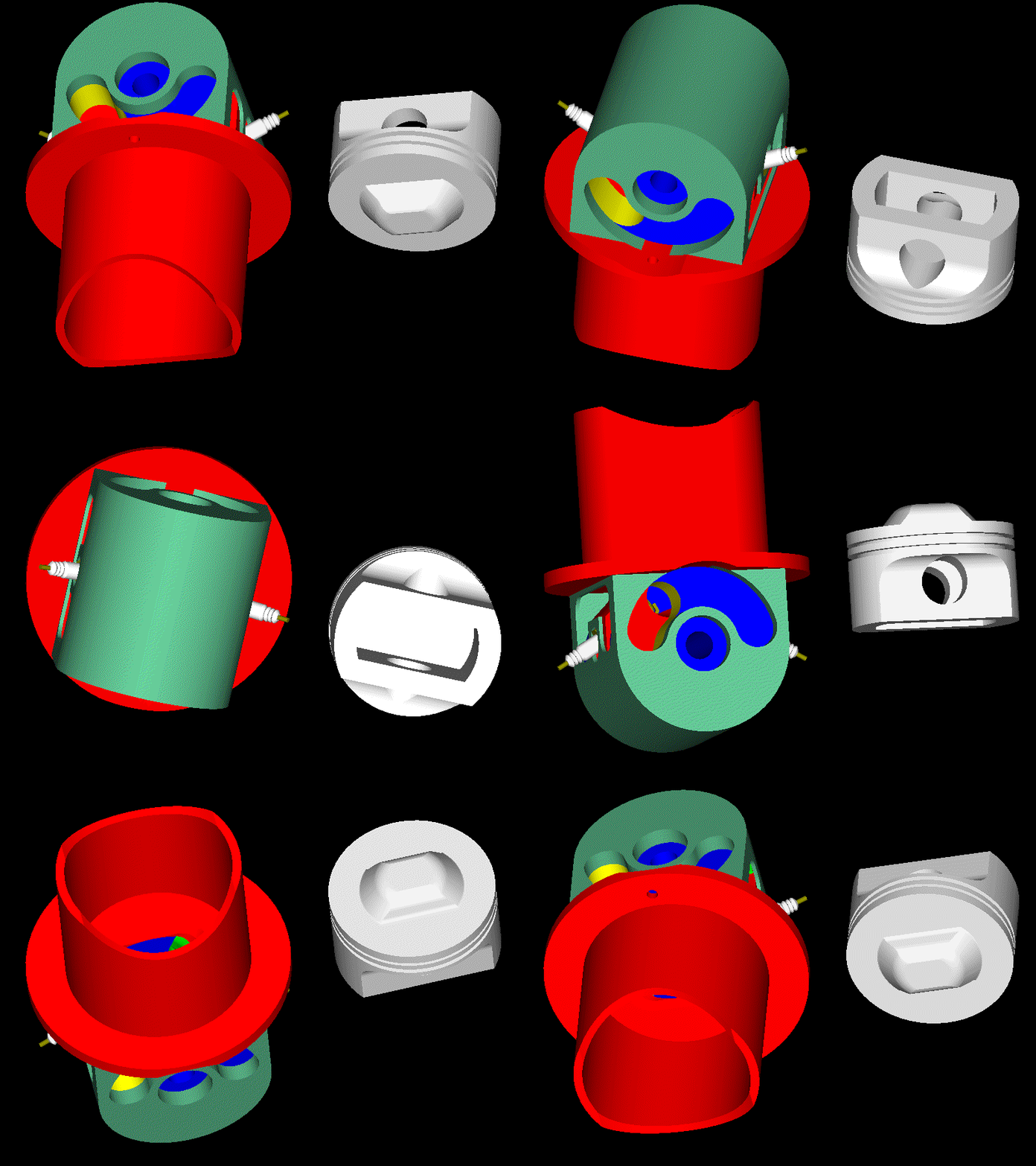
This animation:
http://www.pattakon.com/PatRoVa/PatRoVa_Marc2.gif
shows a way (there are others) to have, in a PatRoVa reciprocating engine, as high compression ratio as you want, without compromising with the ports size: an extension on the piston crown occupies, when the piston is at the TDC, a part of the cavity increasing the compression ratio.
The size of the ports can be as big as you like.
The free flow of the gas is not affected.
That modification just adds more surface area to the combustion chamber, it already has far to much surface area, calculate the surface area ratios, from -15 to +15 of tdc, that will reveal the amount of heat quenching, heat flux, the energy lost from combustion.
I note that it also has two plugs, an attempt to show them to be an advantage which is contrary to your comments when someone else does it. Having two plugs in such a small area will have no significant effect except consume more power, add cost, size and weight
The modification also will making the design worse off the more you try to increase the port size.
Having two air flows flowing into one another does not = "free flowing", fluid flow is dictated by pressure and if one flow is increasing the pressure on the other side of the window then the flow will
NOT be free flowing. It will be chocking.
Each flow negatively effects the others flow through the opposing window, and increases the pumping losses. This is simple fluid flow mechanics.
The windows can be substantially bigger than Bishop's (the same cylinder head can be used on smaller and smaller capacity cylinders).
is the same as
" A bigger and bigger head can be used on the same engine."
One wants to decrease the size and mass of engines as much as possible, heard of "light weighting" and "down sizing" .
That is one of the many advantages of the bishop rotary valve, its small size and weight, high flow co-efficiency, using a single flow stream straight down the centre of the cylinder, creating its unique 'dual cross tumble flow' turbulence enhancement that halves the effective bore to stroke ratio that takes no energy from the flow energy.
Here is why "
The bishop windows can be substantially bigger than the PatRoVa's and flow far greater volumes
In the CRF450 instance with a bore of 96mm the Bishop can provide a window that flows with much higher coefficient of 88 x 40, With the PatRoVa its windows sizes are constrained by the size of combustion chamber sides, which are directly related to the compression volume, which couldn't possibly match the conservative 44 x 40 mm each side, let alone increased by the amount needed to correct for its lower flow coefficient when the approximate chamber size is 30 x 30 x 30 mm. Changing the geometry has to take into account that the closer the opposing windows are the higher the pressure will be on the inside of the compression volume chamber slowing the flow.
While the bishop valve can be tuned for maximum flow inertia and for maximum use of pressure waves, these alone provide huge advantages at high engine speed taking volumetric efficiency far past 100% that the PatRoVa flow mechansim can't match, the only thing pulling the air molecules into the chamber would be a hugely lower in cylinder pressure, enough to overcome flow velocity and inertia.
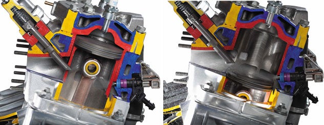
All the sealing issues are solved on the bishop, is may have taken over 10 years, but the result was a very low crevice volumes, your PatRoVa has no sealing so gas can leak into the valve area creating a potentially infinite crevice volume, that will effect the combustion efficiency of each cycle.
The mechanical friction from the PatRoVa cylinder head is negligible.
The mechanical friction related with the Bishop rotary valve is comparable with the mechanical friction related with the piston: the Bishop rotary valve uses a set of seals moving at a constant speed, which is comparable to the mean piston speed.
During the combustion the piston rings move slowly, while the Bishop rotary valve seals move many times faster.
The piston rings are lubricated by a thin film of oil. However, due to the very low magnitude of sliding speed around the top dead center position (TDC), piston rings do not “hydroplane” on the oil film as they do at mid stroke in the cylinder. Consequently, metallic contact at TDC creates wear, and increases friction coefficient very significantly.
While the Bishop valve is rotating in its fully lubricated bearings with relatively constant and very low friction.
Friction is added also by the needle roller bearings of the Bishop rotary valve (this friction is comparable to the friction loss on the crankshaft bearings: their angular velocity is half, however their diameter is big, and as “needle roller bearing” they are not too efficient).
Angular contact ball bearing co-efficient 0.0020
Needle roller bearing with cage co-efficient 0.0020
From SKF, "Estimating the friction of bearings", the ball bearings are the super bearings that Ducati used in the Pantah engines and those that followed, the modern generation v-twin's.
The mechanical power consumed as friction inside the Bishop cylinder head is added to the power output of the PatRoVa.
...
Thanks
Manolis Pattakos
Mechanical efficiency is not much use if it can't flow air efficiently, as evidenced by the following situation ;
The PatRoVa valve mearly provides a ducted path created by the valve and the bottom of the head for the air molecules to pass right by the window due to their velocity and inertia they then follow the duct created by the circumference of the valve, the only way they will seperate from this path is if their is sufficienctly low pressure present at the window to overcome the mole's inertial energy.
The bishop valve allows far higher volumetric efficiency, which provides greater engine efficiency to provide the small amount of power needed to meet the fmep of the seals and bearings. Remember that the valve rotates at a constant speed, one half that of engine speed, with little force from the small seal array, only when cylinder pressure increases does the seal force react. The torque required to drive the bishop valve is far lower than poppet valves, a reduction of 60% has been published and that covers the whole valve's fmep. The torsional load on the gears is far less variable. Its combustion is very fast and efficient the fastest combustion measured in F1 at the time. This is proven in pressure data and extensive CFD.
It is the ideal situation for getting air into and out of the cylinder, nothing beats one single flow that has no flow seperations, nothing in known physics. Two seperate flows that have a convoluted flow path will never match it, and will need a huge amount of energy to get the air into the cylinder, especially where they flow in opposed to one another, that is called a choke point. Maybe some scramjet engineers can explain it to you, there are plenty in Australia, you are trying to achieve supersonic flow through that constricted area. With engines now running with Ultra-Lean mode with Turbulent Jet Ignition Air flow is everything. Lean means more air. Ultra lean means a whole lot more air, and a single flow helps achieve this far more efficiently, remember flow energy is energy it has to come from somewhere, that somewhere is the engine.
With is far superior flow coefficient, use off flow inertia and pressure wave action all features that the PatRoVa does not have
, the superior scavenging, the faster combustion, far less combustion surface area provides more heat and pressure to turn into work, means the bishop engine will produce far more power in each stroke, with only one stroke's worth of friction.
The engineers that worked their heart out to make it a success, remember it started in 1987, took a small team 10 years and millions of dollars, being funded by Bishop's power steering income, their RnD budget was 8-16 million a year. Then Ilmore come on board in 1996'ish and it was in 2002 they had the first V10 F1 engine built, then in 2004 they had the lightest ever 3L V10 that was 77kg vs 96 for the poppet engine, it was fully signed off the same as any engine Ilmore provided to McClaren ready to be bolted to a car (being based on the same bottom end) and have the cooling etc integrated when the rule change came through. Ilmore could no longer continue with it, Bishop was back on its own, and then Arthur Bishop died, owner of the company and it was based on his ideas from rotary valves he pioneered in power steering that made it a viable solution.
Living in Sydney where the bishop rotary valve was all designed there would be one within a small distance away. One can work out that it had a higher rod length ratio closer to the F1 engine, so longer connecting rods, higher compression height, the head is very small from the photo of it next to the Mercedes head published. So having some extra height is not an issue, the performance numbers were publish it was ~77 hp and ~55 nm, with 18% better low down torque, which was good considering it likely had longer rods. That performance is closer to the latest KTM lc4 690cc engine, its torque was a bit lower but it obviously reved higher. Power is just rpm by torque the gearbox ratio does the rotational speed conversion as needed to provide ideal power at whatever speed.
The CRF-450 with the very small bishop rotary valve at 45mm was due to the bottom end, that was all it was deemed to be able to take, increasing it beyond 80 hp was not possible.
It is about time, a world leading product used this valve technology, combined with TJI to show it advantages even more, where no other valve system can come close, their was some personel water craft that used the BRV head, but that was never advertised as having used the bishop valve.
