2 stroke thread (with occasional F1 relevance!)

All that has to do with the power train, gearbox, clutch, fuels and lubricants, etc. Generally the mechanical side of Formula One.
manolis
manolis
107
Joined: 18 Mar 2014, 10:00

Re: 2 stroke thread (with occasional F1 relevance!)

Post

Hello Munixx

You write:
“So in regard to the pre and main chambers, which btw are normally implemented with the pre chamber inside of the main so it is close by and normally only 1-3% of the main chambers volume to keep energy loss to a minimum, and sealing issues simple. You have gone with the complete opposite approach, large pre-chamber, separate and isolated and a large distance away. This is really breaking the mould with pre-chamber design. This brings lots of issues, doubling up the sealing requirements, achieving good fluid flows into the pre-chamber, between pre and main for work and scavenging, and inlet air flow into the pre-chamber.
Back to turbulence and fluid flow, creating turbulence is well known and researched subject, it is generating turbulence without loosing energy in the flows that is the complex issue engineers are allways dealing with.
The issues here are now beyond just a simple examination, they need a huge effort in simulation to understand how it actually works and the pressure gradients that will effect the fluid flows. This will need a customised 3D simulation system, nothing normal with this design, so simulation and modelling will be a costly challenge.”


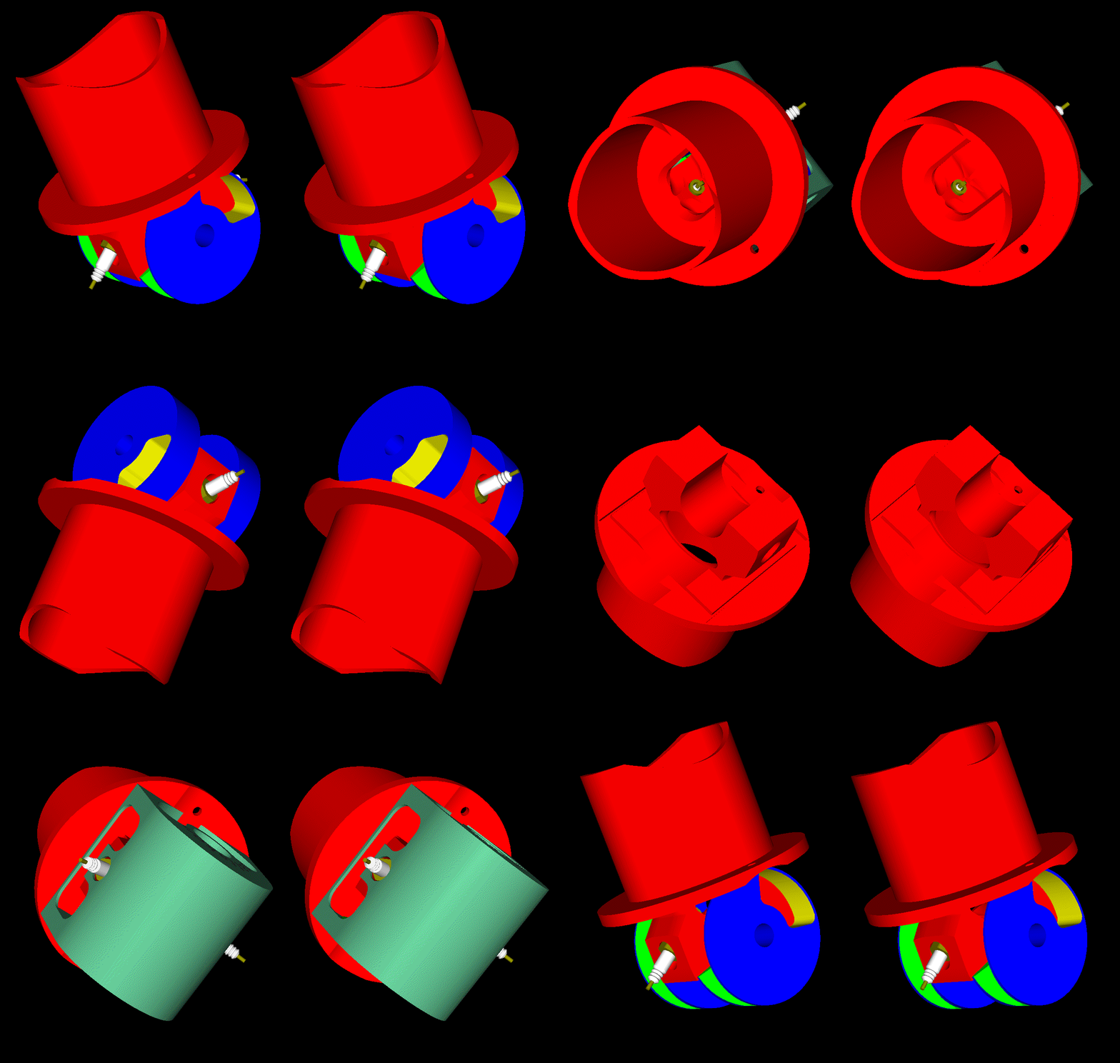
Here is the C-TEC2 600 arctic cat engine:

Image

Here is the Ski-Doo 600 Hoo engine:

Image

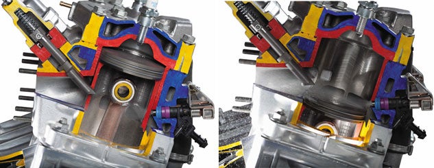
And here is the “combustion cavity” of the Evinrude E-TEC G2:

Image

As 2-strokes, they leave the engine designer free to pick the ideal shape of the combustion chamber / cavity (not possible in a 4-strokes wherein the valves (poppet or rotary) in the cylinder head put several limitations).

Look at the cavity wherein the gas is concentrated at the end of the compression.

I can't see big differences from the shape of the cavity of the PatWankel rotary engine.

Is the burn rate slow?

Is the capacity of the cavity small?


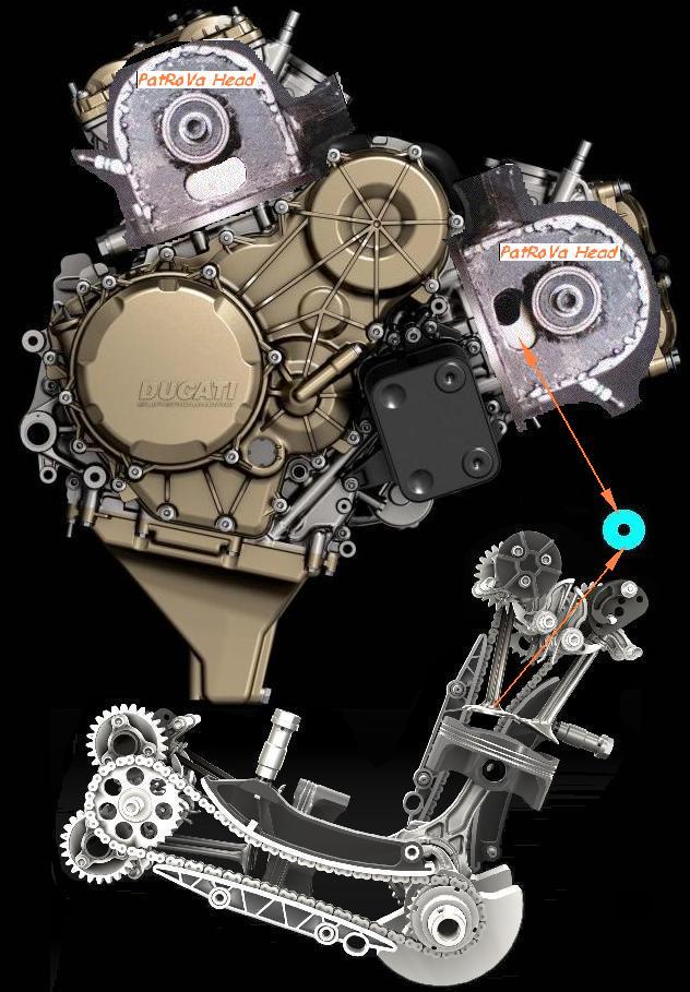
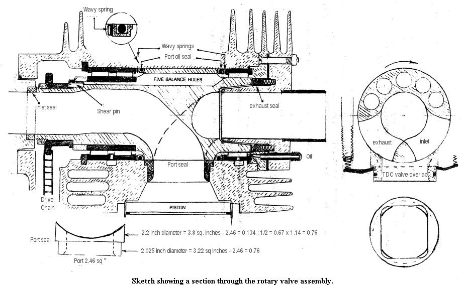
By the way, compare the shape of the “combustion cavity” of the above Evinrude E-TEC G2 2-stroke with the “combustion cavity” of the 4-stroke PatRoVa rotary valve:

Image

which, by the way, eliminates / removes all the friction and all the lubricant from the cylinder head and enables as high revving as the underneath mechanism (piston / con-rod / crankshaft / casing) can stand.

Isn't this friction reduction significant as compared to the friction in a poppet valve cylinder head or to the friction in a Cross, or a Cross-Bishop rotary valve cylinder head?


Back to the PatWankel:

The PatWankel is about a substantially different shape (3-D curved instead of cylindrical) of the central working surface that ends smoothly – progressively onto the two side-flat-working surfaces, enabling a different sealing, reduced gas leakage etc.

Concentrate on this (and on the new opportunities it offers) and forget the simulations.
The design by itself provides lots of turbulence without energy loss or thermal loss, just like in the abovementioned 2-strokes.

Compare the “sealing grid” of the Wankel )the number of parts, the gaps between them etc), the cooling of its seals, its excessive gas leakage (it is equivalent with the gas leakage from a 1.5mm in diameter hole on the piston crown of a slow-revving 650cc reciprocating piston engine, see previous posts), and its slow and incomplete combustion with those of the PatWankel rotary (the patent of Felix Wankel about the "Wankel Sealing Grid" is at http://www.pattakon.com/PatWankel/US3064880.pdf ) .

Thanks
Manolis Pattakos

Muniix
Muniix
14
Joined: 29 Nov 2016, 13:29
Location: Sydney, Australia

Re: 2 stroke thread (with occasional F1 relevance!)

Post

Looking at all the drawing of the PatWankel it looks like the spark plug is inside an internal combustion (pre-) chamber and the combustion expands out into the main / working chamber, is this the principle. It is not at all that clear, some drawings show plugs internal to the rotor, near the centre almost. where the inlet gasses intake, is this correct? because very few drawings actually clearly show the spark plugs/ignition device and one drawing appears to show this arrangement. From an outsiders perspective without prior knowledge this is what appears to be the situation and supported by your comments that combustion happens iso-choric in a constant volume, like the liquidpiston. The liquidpiston animation you showed has the combustion coming from within the rotor.

Maybe some drawings could clarifing this.

If so how far does the gas travel between pre-chamber spark initiation point and main chamber?
If not, then how goes the combustion process?

The timing process, looks like it is fixed, is there any way of varying the intake / exhaust timing or duration? to suit load?

Simulation will show you what WILL happen, not what you think happens. The pressures on the seals, temperatures on the seals, the air flow and pressures, turbulence etc. All very usefull stuff when designing an engine, then it can be optimised before it is built, and when it is built when can compare with experimental results to expected results and determine why.


Anyway sealing issues would be the main issue, how can an effective seal pressure be achieved with such a large seal array?
As the combustion pressure varies from very low to very high, 100 bar or so, this will push on the exposed surfaces of the seals, in the adjacent chamber will be a different pressure, due to different combustion stage, coefficient of variance in combustion etc. This will lead to the seals being pushed against the side of their grooves, as will rotation forces be pushing them, increasing friction causing the seals to sieze.
The gas pressure will get between the seals and the surface they are sealing against and collapse the seal.
Thermal expansion will cause the seals to sieze
Gaps between the seal elements will change due to thermal expansion and cause blow-by
etc.

manolis
manolis
107
Joined: 18 Mar 2014, 10:00

Re: 2 stroke thread (with occasional F1 relevance!)

Post

Hello Muniix.

You write:
“Looking at all the drawing of the PatWankel it looks like the spark plug is inside an internal combustion (pre-) chamber and the combustion expands out into the main / working chamber, is this the principle. It is not at all that clear, some drawings show plugs internal to the rotor, near the centre almost. where the inlet gasses intake, is this correct? because very few drawings actually clearly show the spark plugs/ignition device and one drawing appears to show this arrangement. From an outsiders perspective without prior knowledge this is what appears to be the situation and supported by your comments that combustion happens iso-choric in a constant volume, like the liquidpiston. The liquidpiston animation you showed has the combustion coming from within the rotor.
Maybe some drawings could clarifing this.”

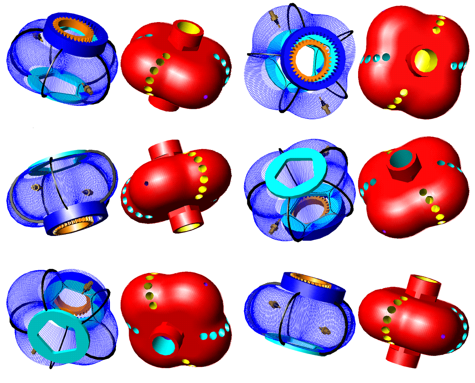
Image

Image

Image

Image

Image


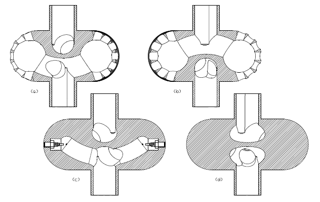
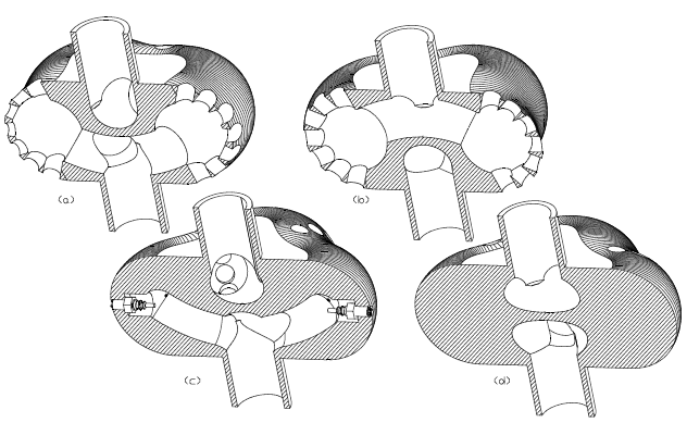
Isn’t it obvious, from the above drawings / animations, the position of the spark plug and the way it can be mounted?


Quote from the PatWankel web page at http://www.pattakon.com/PatWankel.htm :

“The inner body has intake and exhaust ports and passageways, it also has ducts for the installation of the spark plugs and/or injectors, etc.

There is plenty of space enabling the installation of the ignition system (including the generation of the electric current required for the ignition) inside the inner body, near the intake ducts (to avoid overheating).

The spark plug holes on the working surface of the inner body pass over the seals of the chamber at the end of the expansion (i.e. way later than in the Wankel rotary engine) reducing several times the relative leakage”

End of Quote.


The word “pre-chamber” is not mentioned in the above web page because there is no need for pre-combustion chamber.
On the external body there is a cavity / a recession wherein almost all the gas is concentrated at the end of the compression in a way similar to the two-strokes of the last post.
So, the working combustion chamber comprises a “cavity” at its top wherein all the compressed gas is squeezed at the end of the compression:

For instance, in the following drawing:

Image

at top-left all the gas previously entered into the one working chamber is concentrated inside the “left” cavity (formed in the outer body).
The inner body has a hole (its end is shown) through which the spark plug “sees” (and actually sweeps; think the case of a model PatWankel engine with a glow plug in the place of the spark plug) the cavity with the compressed gas.
The spark plug cannot extend outside the working surface of the inner body (otherwise there will be collision of the spark plug with the seals).
The end of the spark plug can be, say, 0.5mm from the working surface.
A single spark plug mounted on the one lobe of the inner body can serve all the three combustion chambers.
The hole for the spark plug passes over a seal only at the end of the expansion, i.e. way later than in the Wankel rotary engine, reducing several times the relative leakage
The spark plug is actually located at the “center” of the above “cavity” (say, as in the Evinrude E-TEC G2 in the previous post).
Obviously, multi spark plugs can be used. There is space in the inner body.
In comparison, in the LiquidPiston XMv3 they use three spark plugs which cannot be located centrally.

So, the spark plug hole on the working surface of the inner body is just a hole through which the spark plug communicates with the “combustion cavity” (and not the entrance of a pre-combustion chamber (however, it is obvious how a pre-combustion chamber could be form and function in such designs).


You also write:
“Anyway sealing issues would be the main issue, how can an effective seal pressure be achieved with such a large seal array?”

Ask yourself how the Wankel achieves it (the sealing of the pressure). Because it achieves it. Not perfectly, but acceptably well.

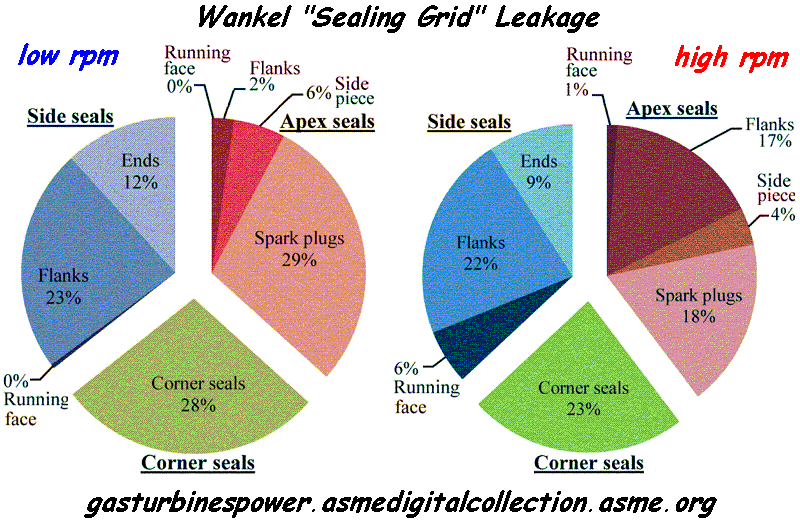
Then read carefully the abstract of the ASME paper in previous post, and think how much more efficient the sealing of a Wankel would be in case the gaps between the seals (those comprising the “Wankel Sealing Grid”) were eliminated.
Just read the numbers:

Image

Focus on the percentages regarding the “Running face” and think again what the “PatWankel” project is about.

Thanks
Manolis Pattakos

manolis
manolis
107
Joined: 18 Mar 2014, 10:00

Re: 2 stroke thread (with occasional F1 relevance!)

Post

Hello all.

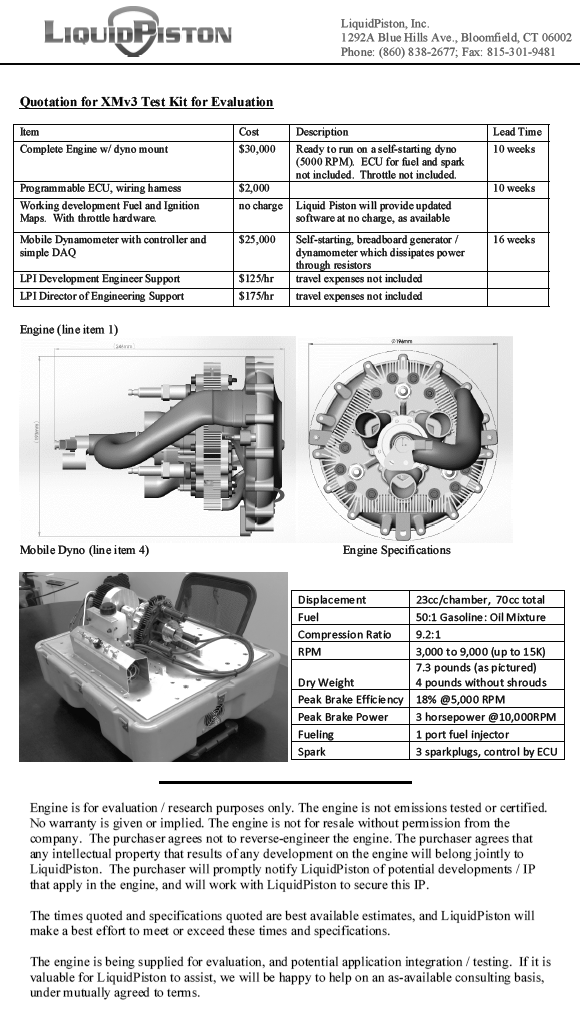
Here are the specifications of the XMv3 of LiquidPiston:

Image

According the famous MIT university, the DARPA and the more than famous Shikorsky company, it is a promising engine design.


Here are a few calculations based on the above specifications and on the way the XMv3 operates.

They are required two only rotations of the eccentric shaft in order a combustion to take place in each working chamber (of the three existing). This means 1.5 combustion per eccentric shaft rotation.

In comparison, in a Wankel they are required three eccentric shaft rotations in order a combustion to take place in each working chamber (of the three existing). This means one only combustion per eccentric shaft rotation.

More combustions per shaft rotation sounds great.

However there is a significant side effect:
In the Liquid Piston the synchronizing gearing is heavily loaded by the combustion pressure.
Depending on the angle of the eccentric shaft, the teeth of the two gearwheels take a good percentage of the force acting on the “rotor” due to the high pressure gas.

In comparison the synchronizing gearing of a Wankel runs unloaded for as long as the engine runs at constant rpm.


At 10,000rpm the power output of the XMv3 is 3PS.

According the previous, 10,000rpm means 5,000combustions per working chamber of the XMv3.

Unless I am wrong, this is equivalent to a 70cc 4-stroke reciprocating piston engine operating at 10,000rpm (because it also burns 5,000 times the mixture contained in a chamber of 70cc).

A good 4-stroke makes more than 100mN of torque per lit (1,000cc) of displacement (even at the peak power revs).
This way, a torque of 7mN from a 4-stroke 70cc reciprocating piston engine is reasonable.

7mN at 10,000rpm means a power output of 14*7mN*10= 10PS.

This is more than 300% more than what the XMv3 makes.

Do I miss something?

Thanks
Manolis Pattakos

Muniix
Muniix
14
Joined: 29 Nov 2016, 13:29
Location: Sydney, Australia

Re: 2 stroke thread (with occasional F1 relevance!)

Post

manolis wrote:Hello all.

Here are a few calculations based on the above specifications and on the way the XMv3 operates.

They are required two only rotations of the eccentric shaft in order a combustion to take place in each working chamber (of the three existing). This means 1.5 combustion per eccentric shaft rotation.

In comparison, in a Wankel they are required three eccentric shaft rotations in order a combustion to take place in each working chamber (of the three existing). This means one only combustion per eccentric shaft rotation.

More combustions per shaft rotation sounds great.

However there is a significant side effect:
In the Liquid Piston the synchronizing gearing is heavily loaded by the combustion pressure.
Depending on the angle of the eccentric shaft, the teeth of the two gearwheels take a good percentage of the force acting on the “rotor” due to the high pressure gas.

In comparison the synchronizing gearing of a Wankel runs unloaded for as long as the engine runs at constant rpm.


At 10,000rpm the power output of the XMv3 is 3PS.

According the previous, 10,000rpm means 5,000combustions per working chamber of the XMv3.

Unless I am wrong, this is equivalent to a 70cc 4-stroke reciprocating piston engine operating at 10,000rpm (because it also burns 5,000 times the mixture contained in a chamber of 70cc).

A good 4-stroke makes more than 100mN of torque per lit (1,000cc) of displacement (even at the peak power revs).
This way, a torque of 7mN from a 4-stroke 70cc reciprocating piston engine is reasonable.

7mN at 10,000rpm means a power output of 14*7mN*10= 10PS.

This is more than 300% more than what the XMv3 makes.

Do I miss something?

Thanks
Manolis Pattakos
I was thinking the very same thing, came to the same conclusion, even if you calculate it at the 23cc size it is a heavily flawed engine.

Remembering that an engine is a air pump that just happens to use combustion to produce some rotation energy in the process. So you need to get air through the thing really efficiently with as little flow losses as possible, using every fluid flow trick you can due to valves opening and closing, so pressure wave action is important, and getting the exhaust out. It is a bit like designing a GPU core or cluster, performance is achieved by optimising how many instructions one can 'complete' per cycle. It is no good doing just one bit well, if the rest fails to perform. The automated optimisation processes using simulation are equally applicable to engines as in gpu's/cpu's.

Then one can optimise the combustion process, where pre-chambers are where research, Formula 1 and future designs are at this moment in time.

Manolis, sorry I had pre-chambers on the brain, I see pre-chambers everywhere at the moment at work, home, on holidays they are everywhere! Holidays are over now. Surrounded by the heat of gpu cores crunching the fluid flow's and combustion cfd of various pre-chamber designs.

The seals in the PatWankel, there is a large surface area in the sealing array, achieving the correct balance of sealing force without creating excessive friction is going to be a major challenge as is lubricating the seals. The heat energy and acoustic energy the seals experience from combustion on their exposed surfaces will push them away collapsing the seal and leaking the gasses. It will need huge pressure creating massive friction. The LiquidPiston uses 50:1 pre-mixed fuel/oil, which will create emissions issues.

The Mazda rotary has apex and side seals optimised for their environment. You have compromised the design by merging them into one that will bring its own diffaculties and challenges, resulting in achieving neither very well and require years if not decades to get to work if at all possible.

Then you have to get the fluid flow of air through the engine, how can one optimise use of pressure waves?

The PatRoVa has similar issues with not being able to use pressure waves action, as the wave will pass straight passed the window, as the intake doesn't terminate into the cylinder, it terminates in the rotating valve, high speed engines must use the pressure waves to achieve the air flow needed to support high operating speeds.

manolis
manolis
107
Joined: 18 Mar 2014, 10:00

Re: 2 stroke thread (with occasional F1 relevance!)

Post

Hello Munixix

You write:
“The seals in the PatWankel, there is a large surface area in the sealing array, achieving the correct balance of sealing force without creating excessive friction is going to be a major challenge as is lubricating the seals.”


Take another look at the pie-plot of ASME (two post above) and spot on what is the leakage through the “running faces” in comparison to the leakage through the gaps between the several different parts of the sealing grid.

The friction in a Wankel, or in a LiquidPiston, or in a PatWankel comes, almost exclusively, from the seals sliding on the working surfaces.
There are no thrust forces (and friction) between piston skirts and cylinder liners (the main source of friction as you wrote in previous post).
There is no valvetrain, no friction related with a valve train (without poppet valves and without rotary valves requiring additional sealing means (as in the Bishop rotary valve) the “breathing” mechanism adds no mechanical friction).


You also write:
“The heat energy and acoustic energy the seals experience from combustion on their exposed surfaces will push them away collapsing the seal and leaking the gasses. It will need huge pressure creating massive friction.”

According the Internet, the Sealing Grid of the Wankel RX-8 Renesis has a TBO from 50,000 to 100,000 miles.
Worth to mention: many of these cars had a hard life in the hands of enthusiast young drivers.


You also write:
“The Mazda rotary has apex and side seals optimised for their environment. You have compromised the design by merging them into one that will bring its own diffaculties and challenges, resulting in achieving neither very well and require years if not decades to get to work if at all possible.”

The multipiece seals (and the several gaps between them) around each working chamber of a Wankel is not an option. It is a necessity.
Avoiding the gaps is a significant step ahead (see in the abovementioned plot the sources of gas leakage in a Wankel).
A seal leaking badly cannot survive for long.

Similarly, the two spark plugs in a Bishop Rotary is not an option, it is a compromise.
If the combustion chamber of the Bishop rotary was really good, some two-stroke engines would use it (because the 2-stroke engine designers are completely free to choose the shape of the combustion cavity/chamber and the number of the spark plugs per combustion chamber).

The PatWankel brings the sealing of the reciprocating piston engines in the rotary engines.

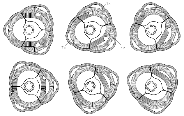
Image

With an independent seal, and an independent groove, per working chamber, the sealing is even closer to the reciprocating piston engines sealing.

In the above animation the ports are for heavy Atkinson Miller cycle.

At high revs, the centrifugal forces on the seals reduce the “bias” between seal and working surface. This saves friction.


You also write:
“The PatRoVa has similar issues with not being able to use pressure waves action, as the wave will pass straight passed the window, as the intake doesn't terminate into the cylinder, it terminates in the rotating valve, high speed engines must use the pressure waves to achieve the air flow needed to support high operating speeds.”

Unless it is confidential, what is the peak power (and at what revs) of the CRF450 Bishop prototype engine?

How the Bishop CRF450 prototype engine handles the partial load operation (how the intake and the exhaust are isolated “inside” the casing of the rotary valve, above the combustion chamber). Was their CRF450 design emission compliant?

Regarding the “breathing inefficiency” you see in the PatRoVa:
What is your estimation for the peak power ceiling of a CRF450 modified to PatRoVa?

Thanks
Manolis Pattakos

manolis
manolis
107
Joined: 18 Mar 2014, 10:00

Re: 2 stroke thread (with occasional F1 relevance!)

Post

Hello all

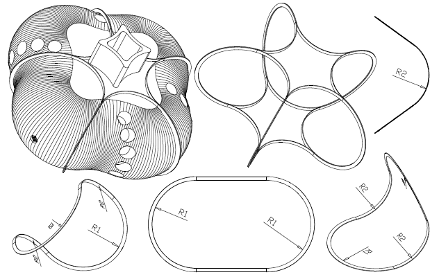
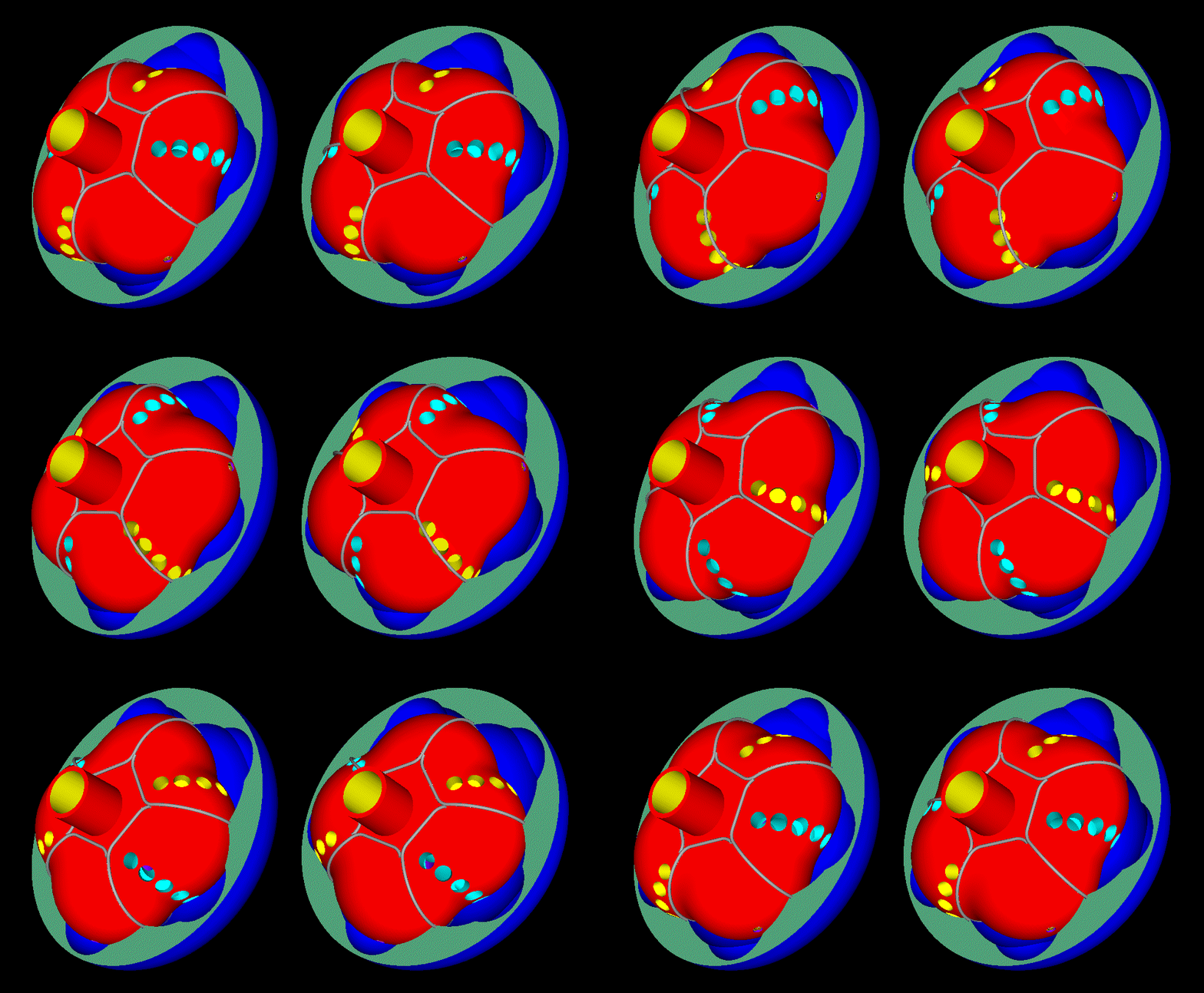
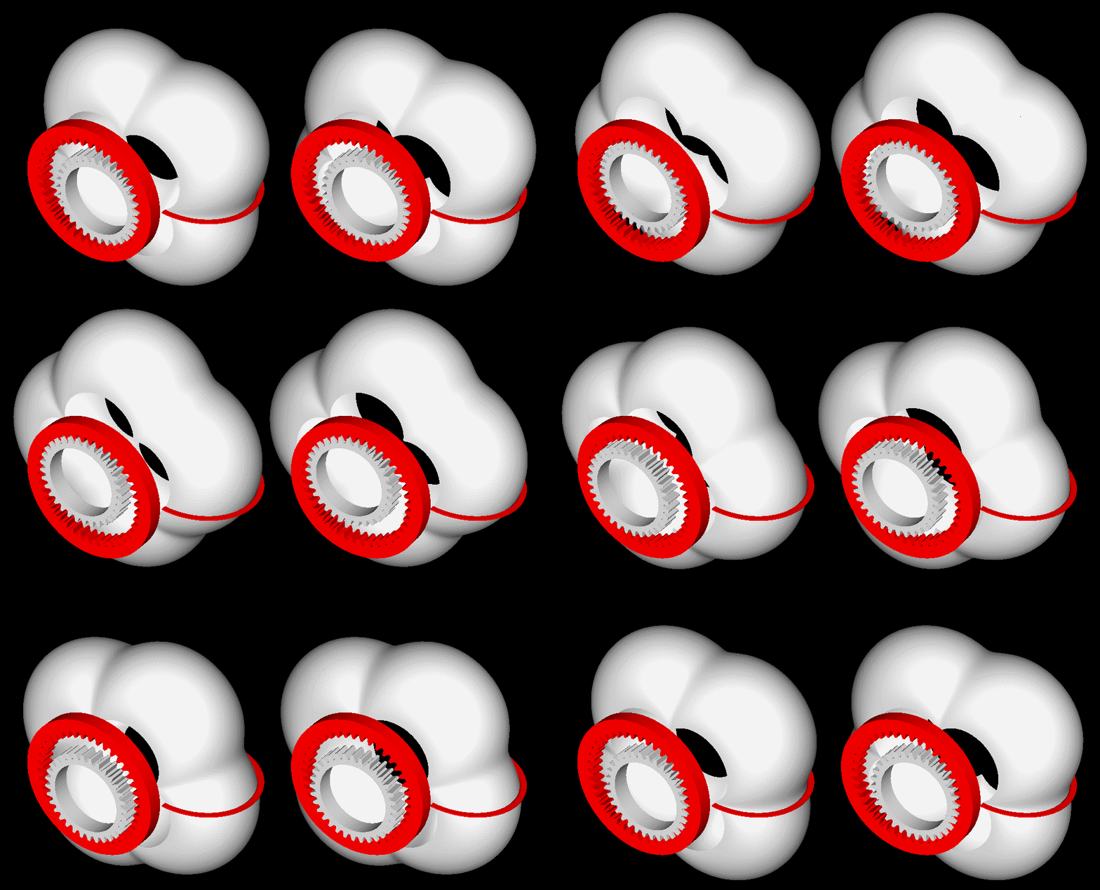
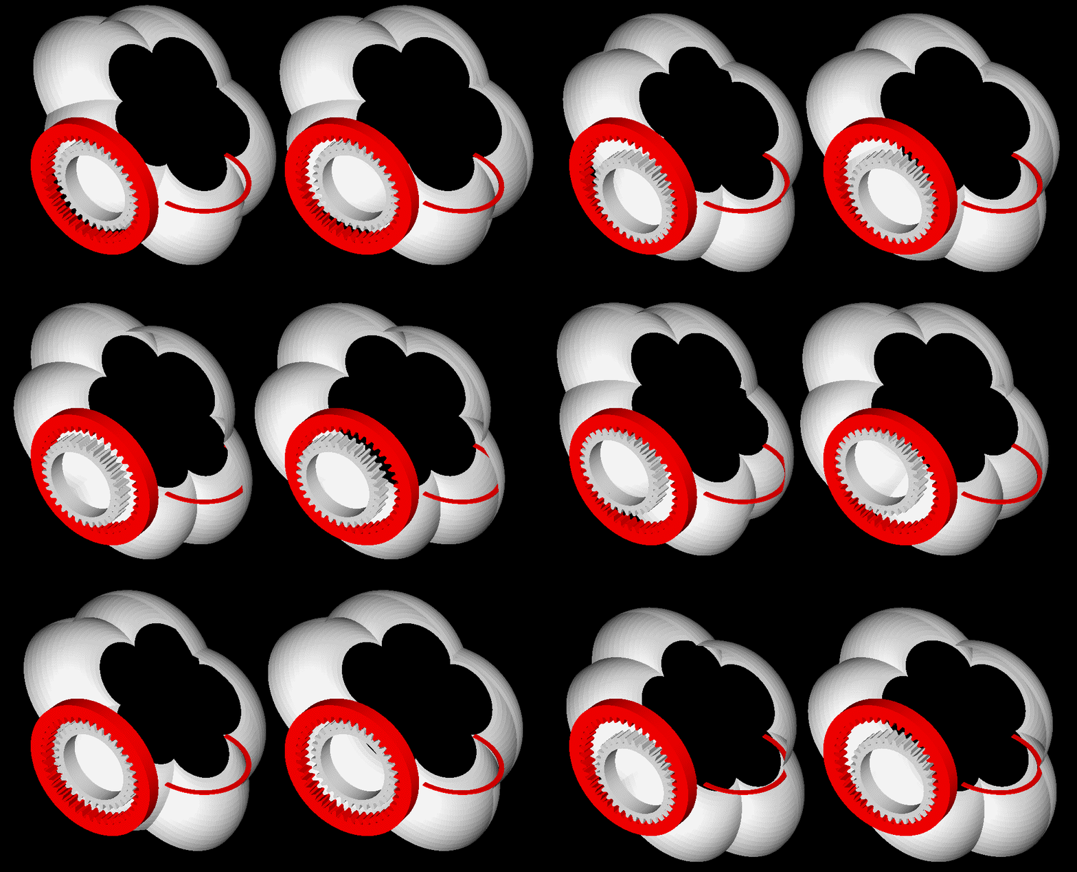
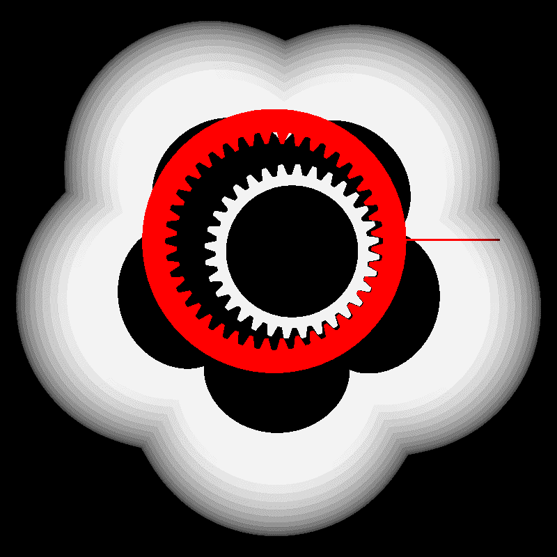
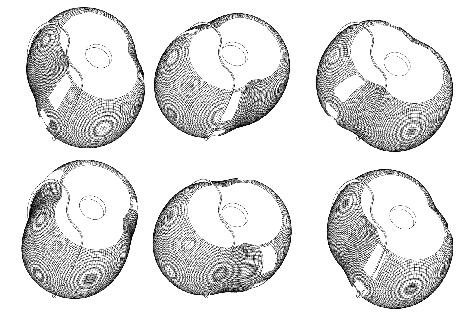
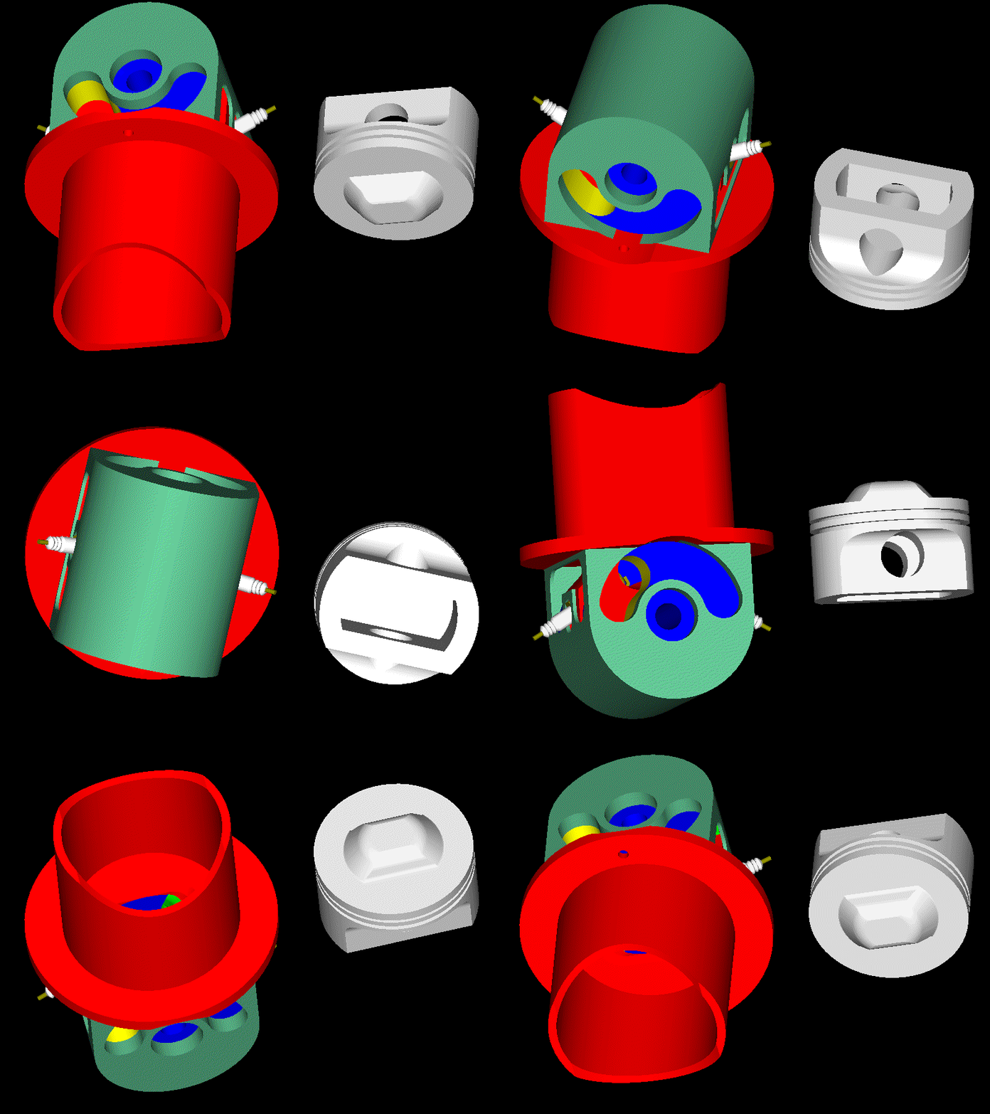
Here is the inner body of the five-“cylinder” PatWankel rotary engine and the way to cut it in a lathe:

Image

(instructions in how to see it stereoscopically at http://www.pattakon.com/pattakonStereoscopy.htm )


At operation it would be like:

Image


Regarding the machining of the working surface (the only surface that needs high accuracy) :

On the chock of a lathe it is secured eccentrically a shaft.

The red gearwheel is secured immovable on the lath bed.

The body with its gearwheel (white) is rotatably mounted on the shaft.

As the chock rotates, the body to be machined performs a combined motion (it spins about the shaft and it orbits together with the shaft).

Given the shape of the seals to be used (the simplest form? the circular), the cutting tool has to follow a specific “path” (like half circle, for instance) in order to create / form the working surface on the part (the working surface is whereon the seals will abut and slide during operation; the seals are mounted in grooves made on the outer body).

In case of seals having simple form, even a conventional (not CNC) lathe can be used.

Similarly for the honing / polishing.


The machining of the outer body can be done in a similar way with the inner body.

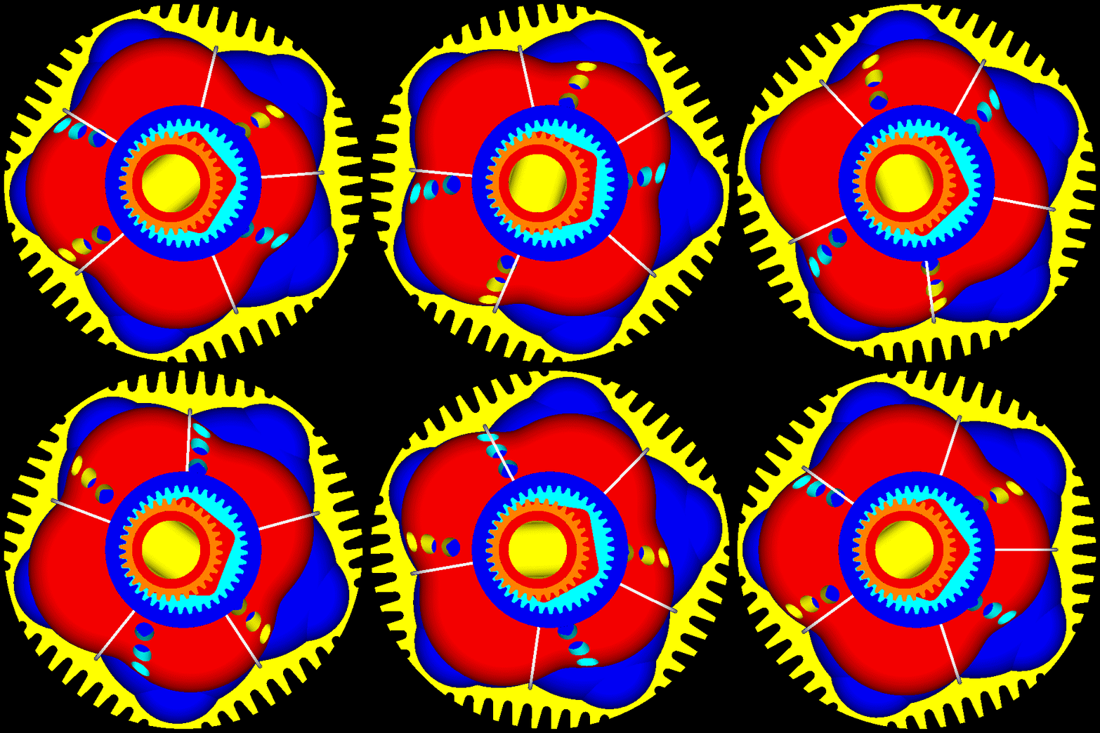
Each half of the casing is located on the eccentric shaft

Image

The red part shows the path of the cutting tool.

For each recess / chamber in the casing, the “white” gearwheel” is properly secured on the half casing (at an eccentricity equal to one quarter of the pitch circle diameter of the white gearwheel):

Image

In the animation it is shown only a part on one rotation. It is supposed the rotation of the lathe chock is continues.

During the first six slides of the animation, the cutting tool is in the air (it cuts nothing).
For the following 19 slides the cutting tool removes material from the one chamber, doing nothing for the rest four chambers.
For the last five slides the cutting tool is in the air again (it cuts nothing).


With the previous machining work, the clearance between the inner body and the outer body can be quite small at operation (like, say, 0.2mm), which means almost all the gas at the end of the compression is concentrated in the “combustion cavity” formed at the “top” of each working chamber, on the outer body.


After machining all five chambers in each half of the casing, the grooves for the seals are machined on a CNC mill. For the grooves the significant dimension is the width (the distance between the two flanks).

If the previous are confusing, please let me know to further explain.

Thanks
Manolis Pattakos

Muniix
Muniix
14
Joined: 29 Nov 2016, 13:29
Location: Sydney, Australia

Re: 2 stroke thread (with occasional F1 relevance!)

Post

manolis wrote:Hello Munixix

You write:
“The seals in the PatWankel, there is a large surface area in the sealing array, achieving the correct balance of sealing force without creating excessive friction is going to be a major challenge as is lubricating the seals.”


Take another look at the pie-plot of ASME (two post above) and spot on what is the leakage through the “running faces” in comparison to the leakage through the gaps between the several different parts of the sealing grid.

The friction in a Wankel, or in a LiquidPiston, or in a PatWankel comes, almost exclusively, from the seals sliding on the working surfaces.
There are no thrust forces (and friction) between piston skirts and cylinder liners (the main source of friction as you wrote in previous post).
There is no valvetrain, no friction related with a valve train (without poppet valves and without rotary valves requiring additional sealing means (as in the Bishop rotary valve) the “breathing” mechanism adds no mechanical friction).


You also write:
“The heat energy and acoustic energy the seals experience from combustion on their exposed surfaces will push them away collapsing the seal and leaking the gasses. It will need huge pressure creating massive friction.”

According the Internet, the Sealing Grid of the Wankel RX-8 Renesis has a TBO from 50,000 to 100,000 miles.
Worth to mention: many of these cars had a hard life in the hands of enthusiast young drivers.
Yes but your sealing array is totally different, experiences totally different forces and is three dimensional whereas the RX-8 is just apex and side seals.
The forces that need to be dealt with are the thrust forces the seals see from combustion pressure, one needs to dynamically adapt to these forces that are trying to seperate the seal from the surface they are abuting to. As pressure rises it will force this seal to collapse, one needs to compensate for this force, while not providing excessive force as to create to much friction whan not needed. This is typically done with gas ports, that allow the cylinder pressure to get behind the seals, this acts like a capacitor, it also has to deal with the sliding friction of the working surface the seals are sliding against, so the pressure between the seal and its slot surfaces needs to be carefully balanced to avoid the seal being forced against one slot face and creating too much friction with that face. A spring behind the seal needs to provide just enough tension to support the minimun sealing force and cover for the period before the gas force is used to assist the sealing force.
You also write:
“The Mazda rotary has apex and side seals optimised for their environment. You have compromised the design by merging them into one that will bring its own diffaculties and challenges, resulting in achieving neither very well and require years if not decades to get to work if at all possible.”

The multipiece seals (and the several gaps between them) around each working chamber of a Wankel is not an option. It is a necessity.
Avoiding the gaps is a significant step ahead (see in the abovementioned plot the sources of gas leakage in a Wankel).
A seal leaking badly cannot survive for long.

Similarly, the two spark plugs in a Bishop Rotary is not an option, it is a compromise.
If the combustion chamber of the Bishop rotary was really good, some two-stroke engines would use it (because the 2-stroke engine designers are completely free to choose the shape of the combustion cavity/chamber and the number of the spark plugs per combustion chamber).
Here you are wrong again, using two offset plugs when combined with the squish action actually creates a larger central flame kernel than a single central plug can, this has been explained in these forum many times.
The way it works is the plugs are ignited before TDC and the flame kernels grow to 8mm, had a central plug been ignited it would have grown to 10mm, but then the squish happens and merges these two kernels at the centre, now their is a 22 mm oval shaped flame kernel much larger than the single plug flame kernel would be at the same crank angle. So it actually is far superior, their is far greater flame surface area to heat the gasses. This is well known by many on these forums and been explained to you several times before, why repeat a falsehood, or as Trump would say Alternative Facts, he has small man syndrome. Lets not drop to his level, please.

Another issue I see with the design is it doesn't seem like it will scavenge the combustion chamber very well at all, it will be very hard to get air flow into the combustion chamber from the working area, while both exhaust and inlet ports are open. The scavenging flow will flow straight through the working chamber and not evacuate the combustion chamber leaving most of its contents intact and left behind, unscavenged. Achieving fast and effective scavenging of the whole area is necessory.
The PatWankel brings the sealing of the reciprocating piston engines in the rotary engines.

http://www.pattakon.com/PatWankel/PatWa ... ller_2.gif

With an independent seal, and an independent groove, per working chamber, the sealing is even closer to the reciprocating piston engines sealing.
Except is isn't like a piston ring seal, it has a combustion chamber on each side of it, with the hugely varying acoustic and thermal combustion energy against the seals exposed surfaces, some force from somewhere will need to oppose these forces or deal with the thermal and pressure effects, like expansion, where do they expand into? is there a gap, and if so what effects would that have? Seals are a night mare on any engine, identifying the exact conditions they are operating with over the combustion cycle and having a mechansim to handle each and every one needs to be engineered in to have a hope of a viable solution, saying something is so, does not make it so.
In the above animation the ports are for heavy Atkinson Miller cycle.

At high revs, the centrifugal forces on the seals reduce the “bias” between seal and working surface. This saves friction.


You also write:
“The PatRoVa has similar issues with not being able to use pressure waves action, as the wave will pass straight passed the window, as the intake doesn't terminate into the cylinder, it terminates in the rotating valve, high speed engines must use the pressure waves to achieve the air flow needed to support high operating speeds.”

Unless it is confidential, what is the peak power (and at what revs) of the CRF450 Bishop prototype engine?

How the Bishop CRF450 prototype engine handles the partial load operation (how the intake and the exhaust are isolated “inside” the casing of the rotary valve, above the combustion chamber). Was their CRF450 design emission compliant?
Going on the available information (and some grey matter) the Bishop CRF engine had a very small diametre valve, maybe 45 mm, they also used a very novel throttle valve, that used 6 plates that closed from the outside in and this generated swirl when partially closed and no obstruction to flow when fully open, they were indeed clever people, this maintained a more constant air speed as the diameter was reduced as the throttle closed. The injector when it fired was effectively firing straight into the cylinder, none of this injecting onto the back of a valve head crap, the air flow took it straight into the engine, combined with all that swirl. That is why is had such an improved low end torque, up 18%. The CRF 450 had a bore to stroke ratio of 1.54:1 about the worst ratio for the bishop, the air flow doesn't know if it is going to tumble or generate two counter rotating vortices. Had they changed to a 104mm bore with 49mm stroke, 100 hp would have been achieved at 15krpm for the same 449cc and moto2 would be a whole lot more interesting with this motor. As it was the bishop crf motor produced 30% more power than the standard one did which was 55hp, so about 75hp without pushing the piston speed. Torque was up 11% at peak speed but this was handicapped by the small inside diameter of the valve.

The sealing issues on the Bishop was extensively studied and all the flows and forces identified, their are two axial seals and two circumferential seals around the window, these seal the combustion gasses, and provide a very small crevice volume, using some clever overlapping system the only possible path for any blow by gas is for it to be re-admitted back into the cylinder on the next cycle. So no blow-by was released into the exhaust gasses, so low emissions. Clever use of combustion force is used to increase seal force and protect the seals from the effects of friction of the rotating valve and seal force is reduced to what the springs provide at other times to reduce friction. Valve inertia and blow-by gas forces are used to reduce the load on the valves support bearings, for every action their is a equal and opposite re-action. Clever people took from their environment and used it to provide a working solution.
Regarding the “breathing inefficiency” you see in the PatRoVa:
What is your estimation for the peak power ceiling of a CRF450 modified to PatRoVa?
Depends on how big you want to make the valve, and the maximum window size that can be achieved in the little prechamber, if running at 15:1 CR then the pre-chamber volume would be a small cube that holds ~28 cc's, about 30 mm cubed without geometric optimisation, that would have small windows on each side and the air flow would be streaming into one another, slowing each others flow, and increasing the pressure anyway which will slow the flow down. That is not a good start for a high flowing engine. Then their is the friction on the two surfaces as the air speed increases. Flow through a right angle window has a very low coefficient of flow, unless you can implement a feature that avoids flow seperation like the bishop valve does, where the flow has no choice but to flow down into the cylinder being turned by the throat section, this is what gave it the high flow coefficient, the air at the end is turned 90 degress by the geometry on the roof of the valve, the air flow at the floor is turned 60 degrees. But on the PatRoVa the air has to turn and head down into the cylinder being pulled by the piston motion only and the reduced pressure in the combustion chamber, flow inertia actually works against you as the air will flow straight passed the window, this will increase the pumping losses. Also as the valve initially opens the pressure wave will travel both direction in the valve as it rotates and reflect from both ends, this will make tuning to take advantage of pressure waves difficult. Every problem has a solution, but solutions with less problems, or where the problems have known proven solutions are normally better.
Then the PatRoVa with its small combustion pre-chamber and main chamber that exposes a huge surface area to combustion, so the surface area from 10 degrees before to 10 degrees after, that is a lot of surface area that will quench the combustion, and cause lots of squish flows in areas you don't want them, and expanding areas that lower temperatures. It is not the ideal environment to extract work out of combustion.

Thanks
Manolis Pattakos

manolis
manolis
107
Joined: 18 Mar 2014, 10:00

Re: 2 stroke thread (with occasional F1 relevance!)

Post

Hello Muniix

You write:
“Yes but your sealing array is totally different, experiences totally different forces and is three dimensional whereas the RX-8 is just apex and side seals.
The forces that need to be dealt with are the thrust forces the seals see from combustion pressure, one needs to dynamically adapt to these forces that are trying to seperate the seal from the surface they are abuting to. As pressure rises it will force this seal to collapse, one needs to compensate for this force, while not providing excessive force as to create to much friction whan not needed. This is typically done with gas ports, that allow the cylinder pressure to get behind the seals, this acts like a capacitor, it also has to deal with the sliding friction of the working surface the seals are sliding against, so the pressure between the seal and its slot surfaces needs to be carefully balanced to avoid the seal being forced against one slot face and creating too much friction with that face. A spring behind the seal needs to provide just enough tension to support the minimun sealing force and cover for the period before the gas force is used to assist the sealing force.”


It seems you didn’t yet got the mechanism according which the seals in the PatWankel work.

Start with the top ring in the piston of a reciprocating piston engine.
It is made to have a slight preloading to keep its external (or better: working) surface in touch with the cylinder liner.
The pressure in the combustion chamber of the reciprocating engine arrives into the groove of the seal and pushes it towards the cylinder liner and towards the bottom of its groove.
What is so important with it?
The pressure ring abuts heavily onto the cylinder liner only during the high pressure period of the cycle, achieving the necessary sealing at low friction loss.

Think of a bicycle pump, that with the leather seal. During the compression the leather seal is pushed towards the cylinder wall and achieves the required sealing. During the suction of fresh air, the seal adds no friction.

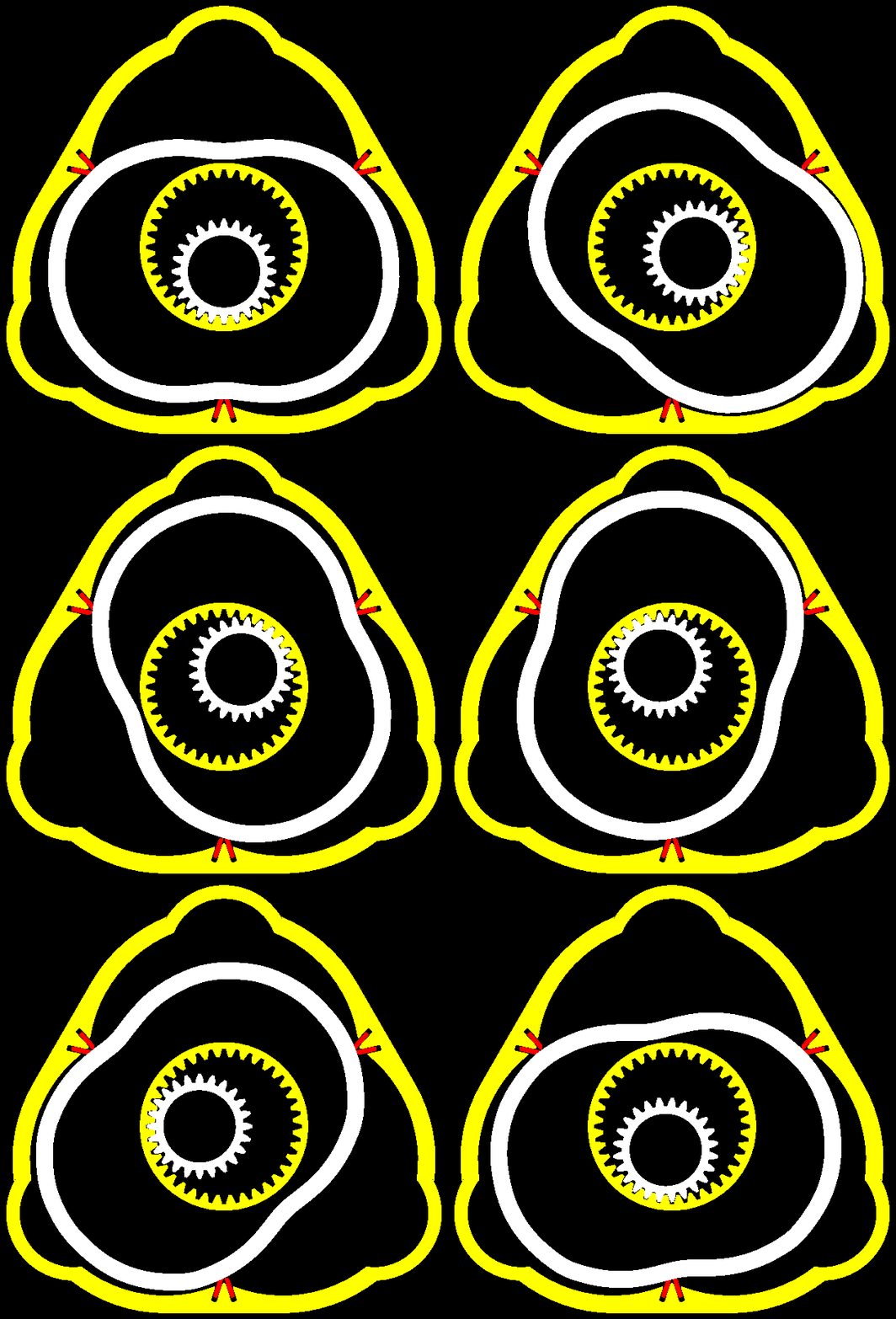
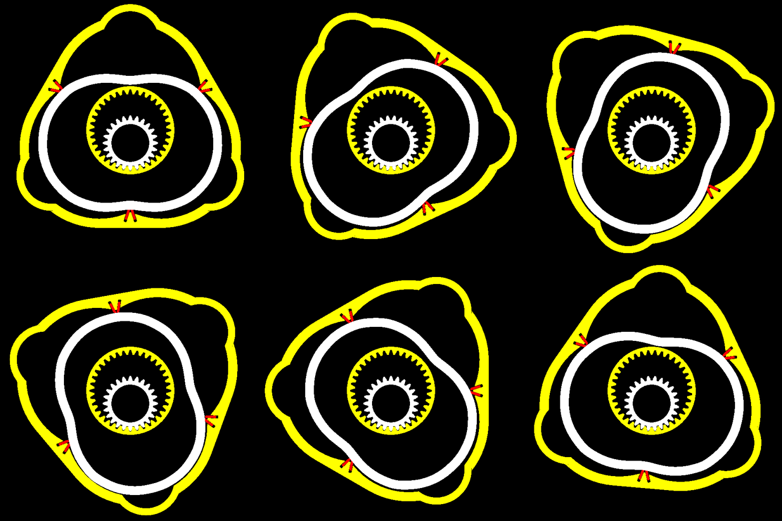
The difference of the PatWankel seals as compared to the reciprocating piston rings is that, depending on the version, the “working “ surface is either the “external surface” of the seal, or the “inner surface” of the seal (version with the working surface on the inner body) like:

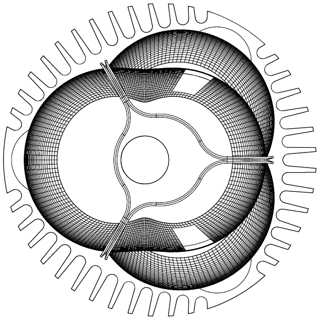
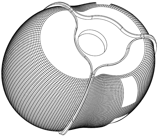
Image

wherein each seal and each groove serve one only working chamber, the working surface (whereon the seals abut and slide) is the external surface of the inner body:

Here is the inner body alone, with the three seals on it:

Image

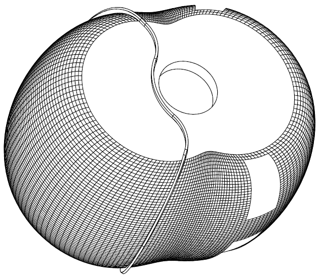
In the following drawing the two, of the three, seals have been removed.

Image

The working chamber at left is at its TDC with its seal surrounding it and sealing it.

The inner body is like a "piston" pushed deaply into the working chamber (an unconventional piston that needs neither a connecting rod, nor a crankshaft).

As the inner and outer bodies (which comprise the engine) rotate, the "piston" (i.e. the inner body), remaining permanently in contact with the seals, is pushed outwards from the chamber and the volume increases (expansion).

The “sealing” principle is the same with the reciprocating piston engines: the pressure in the working chamber is also the pressure inside the groove of the seal. This pressure, during the high pressure period of the cycle, forces the seal towards the “working surface” (and towards the “bottom” of the groove, just like in the reciprocating engines) and seals the working chamber.


Each working chamber has its own / exclusive seal and its own / discrete groove wherein the seal is mounted.

The left side of the inner body shown in the drawing is at the TDC.

The left seal surrounds the one working chamber and abuts on the working surface on the inner body, just like a piston ring abuts on the cylinder liner.

The pressure at the left side of the groove wherein the left seal is inside (not shown in the drawing) equals to the pressure into the “left” working chamber. This pressure, just like in the reciprocating piston engines, presses the seal to abut on the inner body and onto the right side (i.e. the bottom) of its groove.

At operation the "piston" (i.e. the inner body), remaining permanently in contact with the seal, is pushed outwards from the chamber and the volume increases, then the "piston" is pushed inwards and the volume decreases, and so on:

Image

Every point of the inner periphery of the seal remains permanently in contact with the external surface of the inner body


Now, look again at the pie-plot of ASME and think the reduction of the gas leakage in a rotary engine (and the friction reduction, and the wear reduction) in case the “RX-8 apex and side seals (you forgot the four corner (or button) seals that participate in the sealing of each working chamber of the Wankel) and the “cylindrical” design of the Wankel with the infinite curvature at the corners, are replaced by the 3D working surface and the 3D seals of the PatWankel.


You also write:
“Here you are wrong again, using two offset plugs when combined with the squish action actually creates a larger central flame kernel than a single central plug can, this has been explained in these forum many times.
The way it works is the plugs are ignited before TDC and the flame kernels grow to 8mm, had a central plug been ignited it would have grown to 10mm, but then the squish happens and merges these two kernels at the centre, now their is a 22 mm oval shaped flame kernel much larger than the single plug flame kernel would be at the same crank angle. So it actually is far superior, their is far greater flame surface area to heat the gasses. This is well known by many on these forums and been explained to you several times before, why repeat a falsehood, or as Trump would say Alternative Facts, he has small man syndrome. Lets not drop to his level, please.
Another issue I see with the design is it doesn't seem like it will scavenge the combustion chamber very well at all, it will be very hard to get air flow into the combustion chamber from the working area, while both exhaust and inlet ports are open. The scavenging flow will flow straight through the working chamber and not evacuate the combustion chamber leaving most of its contents intact and left behind, unscavenged. Achieving fast and effective scavenging of the whole area is necessory.”


Please do keep the discussion strictly technical. And polite.

In case the Bishop design was better, the 2-stroke designers would use it.

To present a weakness as advantage is not persuasive.


You also write:
“Depends on how big you want to make the valve, and the maximum window size that can be achieved in the little prechamber, if running at 15:1 CR then the pre-chamber volume would be a small cube that holds ~28 cc's, about 30 mm cubed without geometric optimisation, that would have small windows on each side and the air flow would be streaming into one another, slowing each others flow, and increasing the pressure anyway which will slow the flow down. That is not a good start for a high flowing engine. Then their is the friction on the two surfaces as the air speed increases. Flow through a right angle window has a very low coefficient of flow, unless you can implement a feature that avoids flow seperation like the bishop valve does, where the flow has no choice but to flow down into the cylinder being turned by the throat section, this is what gave it the high flow coefficient, the air at the end is turned 90 degress by the geometry on the roof of the valve, the air flow at the floor is turned 60 degrees. But on the PatRoVa the air has to turn and head down into the cylinder being pulled by the piston motion only and the reduced pressure in the combustion chamber, flow inertia actually works against you as the air will flow straight passed the window, this will increase the pumping losses. Also as the valve initially opens the pressure wave will travel both direction in the valve as it rotates and reflect from both ends, this will make tuning to take advantage of pressure waves difficult. Every problem has a solution, but solutions with less problems, or where the problems have known proven solutions are normally better.
Then the PatRoVa with its small combustion pre-chamber and main chamber that exposes a huge surface area to combustion, so the surface area from 10 degrees before to 10 degrees after, that is a lot of surface area that will quench the combustion, and cause lots of squish flows in areas you don't want them, and expanding areas that lower temperatures. It is not the ideal environment to extract work out of combustion.”


This animation:

Image

shows a way (there are others) to have, in a PatRoVa reciprocating engine, as high compression ratio as you want, without compromising with the ports size: an extension on the piston crown occupies, when the piston is at the TDC, a part of the cavity increasing the compression ratio.

The size of the ports can be as big as you like.

The free flow of the gas is not affected.

The windows can be substantially bigger than Bishop's (the same cylinder head can be used on smaller and smaller capacity cylinders).

The mechanical friction from the PatRoVa cylinder head is negligible.

The mechanical friction related with the Bishop rotary valve is comparable with the mechanical friction related with the piston: the Bishop rotary valve uses a set of seals moving at a constant speed, which is comparable to the mean piston speed.
During the combustion the piston rings move slowly, while the Bishop rotary valve seals move many times faster.
Friction is added also by the needle roller bearings of the Bishop rotary valve (this friction is comparable to the friction loss on the crankshaft bearings: their angular velocity is half, however their diameter is big, and as “needle roller bearing” they are not too efficient).

The mechanical power consumed as friction inside the Bishop cylinder head is added to the power output of the PatRoVa.

If you have a dyno of the Bishop CRF450 (the power, or the torque, along the complete rev range), please publish it.

It would be a useful reference.

The “30% increase of the power” says too little (is misleading).
Unless a tuner cannot do the same with poppet valves.
Or unless the Ducati Panigale is not making, per every 450cc, as much power as the modified to Bishop CRF450.

Thanks
Manolis Pattakos

Muniix
Muniix
14
Joined: 29 Nov 2016, 13:29
Location: Sydney, Australia

Re: 2 stroke thread (with occasional F1 relevance!)

Post

manolis wrote:Hello Muniix

You write:
“Yes but your sealing array is totally different, experiences totally different forces and is three dimensional whereas the RX-8 is just apex and side seals.
The forces that need to be dealt with are the thrust forces the seals see from combustion pressure, one needs to dynamically adapt to these forces that are trying to seperate the seal from the surface they are abuting to. As pressure rises it will force this seal to collapse, one needs to compensate for this force, while not providing excessive force as to create to much friction whan not needed. This is typically done with gas ports, that allow the cylinder pressure to get behind the seals, this acts like a capacitor, it also has to deal with the sliding friction of the working surface the seals are sliding against, so the pressure between the seal and its slot surfaces needs to be carefully balanced to avoid the seal being forced against one slot face and creating too much friction with that face. A spring behind the seal needs to provide just enough tension to support the minimun sealing force and cover for the period before the gas force is used to assist the sealing force.”


It seems you didn’t yet got the mechanism according which the seals in the PatWankel work.

Start with the top ring in the piston of a reciprocating piston engine.
It is made to have a slight preloading to keep its external (or better: working) surface in touch with the cylinder liner.
The pressure in the combustion chamber of the reciprocating engine arrives into the groove of the seal and pushes it towards the cylinder liner and towards the bottom of its groove.
What is so important with it?
The pressure ring abuts heavily onto the cylinder liner only during the high pressure period of the cycle, achieving the necessary sealing at low friction loss.

Think of a bicycle pump, that with the leather seal. During the compression the leather seal is pushed towards the cylinder wall and achieves the required sealing. During the suction of fresh air, the seal adds no friction.

The difference of the PatWankel seals as compared to the reciprocating piston rings is that, depending on the version, the “working “ surface is either the “external surface” of the seal, or the “inner surface” of the seal (version with the working surface on the inner body) like:

http://www.pattakon.com/PatWankel/PatWankel_iGR_16.gif

wherein each seal and each groove serve one only working chamber, the working surface (whereon the seals abut and slide) is the external surface of the inner body:

Here is the inner body alone, with the three seals on it:

http://www.pattakon.com/PatWankel/PatWankel_iGR_16A.gif

In the following drawing the two, of the three, seals have been removed.

http://www.pattakon.com/PatWankel/PatWankel_iGR_16B.gif

The working chamber at left is at its TDC with its seal surrounding it and sealing it.

The inner body is like a "piston" pushed deaply into the working chamber (an unconventional piston that needs neither a connecting rod, nor a crankshaft).

As the inner and outer bodies (which comprise the engine) rotate, the "piston" (i.e. the inner body), remaining permanently in contact with the seals, is pushed outwards from the chamber and the volume increases (expansion).

The “sealing” principle is the same with the reciprocating piston engines: the pressure in the working chamber is also the pressure inside the groove of the seal. This pressure, during the high pressure period of the cycle, forces the seal towards the “working surface” (and towards the “bottom” of the groove, just like in the reciprocating engines) and seals the working chamber.

Look again at the above drawing.
Ok, when you say "bottom" you don't mean underside, as the pressure would be pushing it away from the underside and against the far-side edge, away from the combustion origin. So "Bottom" is not the best description, Maybe standardising on Under, Inner and Outer seal edges may be more descriptive. Consistancy is important, also a glossary one can refer to. Just a thought.

Each working chamber has its own / exclusive seal and its own / discrete groove wherein the seal is mounted.
Doubling up on sealing will increase the total seal area, negatively effecting friction mean effective pressure FMEP.
One will need to keep a total frictional area per chamber, manufactured in tension into the seals may not provide sufficient sealing force on its own, nearly guaranteed there will be areas where gas will leak from insuficient seal force, the dynamic nature of the environment means achieving optimal sealing force over the whole length of the seal from tension alone will be highy improbable. Additional force will likely be needed. Combustion CFD will reveal this pretty quickly, as will a pressure sensor revealing the loss of cylinder pressure, you will need to identify how you are going to measure cylinder pressure and seal force pressures to 'tune' and 'optimise' the engine, surface acoustic wave sensors to measure seal force under the seals, these can be made wireless, a friend of mine worked on developing these in Ryde decades ago at the AWA Microelectronics Fabrication facility, just up the road from Bishop, SAW = sensors on a silicon substrate.

Providing sufficient force to survive the delay time it takes for the gas to provide the counter force to maintain a effective seal, the gas force seal pressure assistance is like a capacitor it takes time to charge up and to discharge. One needs to maintain some charge in it at all times to all surface areas. A solution will need to be found for this issue, springs, polymers, the environment is slightly hostile to say the least down under the seal and between its groove, without blocking the gas itself which is needed to apply some force to the far side seal edge, to reduce the pressure on that edge else the seal will stay stuck against the far edge. This is compounded by the rotational frictional force.

There are also issues with the gaps between seals in the same groove, and the pressure between seals of adjacent cylinders. This area will hold blow-by from all chambers, maybe colouring it in a different colour to highlight blow-by areas/potential crevice volumes.

Otherwise it is on its way to a solution for the rotary engine, brings its own new set of issues, which a small team of dedicated talented people have been known to solve given enough resources and the tools to measure all properties they are dealing with.

Their is nothing funnier than watching someone dyno their engine and seeing torque rapidly drop off as engine speed increases, without high speed cylinder pressure sensors to indicate exhaust pressure isn't being blown down fast enough before bdc!!
The left side of the inner body shown in the drawing is at the TDC.

The left seal surrounds the one working chamber and abuts on the working surface on the inner body, just like a piston ring abuts on the cylinder liner.

The pressure at the left side of the groove wherein the left seal is inside (not shown in the drawing) equals to the pressure into the “left” working chamber. This pressure, just like in the reciprocating piston engines, presses the seal to abut on the inner body and onto the right side (i.e. the bottom) of its groove.
Bottom = Far side (outside edge away from compression origin) and away from the seals underside?
Remembering that piston rings have built in tension to provide initial sealing force around a perfectly round piston, this is a nice simple environment for this scheme to work. Your environment is very different it is 3d with infinetly different angles, not the perfect environment for preset tension to provide the initial seal force. Additionally it is a very large sealing area, with differing pressures and temperatures along the seal as each part of the seal will be a different distance from the origin of combustion, so local speed of sound issues for the acoustic energy to have effect on the pressures waves arriving at the seals exposed surfaces.

Now, look again at the pie-plot of ASME and think the reduction of the gas leakage in a rotary engine (and the friction reduction, and the wear reduction) in case the “RX-8 apex and side seals (you forgot the four corner (or button) seals that participate in the sealing of each working chamber of the Wankel) and the “cylindrical” design of the Wankel with the infinite curvature at the corners, are replaced by the 3D working surface and the 3D seals of the PatWankel.


You also write:
“Here you are wrong again, using two offset plugs when combined with the squish action actually creates a larger central flame kernel than a single central plug can, this has been explained in these forum many times.
The way it works is the plugs are ignited before TDC and the flame kernels grow to 8mm, had a central plug been ignited it would have grown to 10mm, but then the squish happens and merges these two kernels at the centre, now their is a 22 mm oval shaped flame kernel much larger than the single plug flame kernel would be at the same crank angle. So it actually is far superior, their is far greater flame surface area to heat the gasses. This is well known by many on these forums and been explained to you several times before, why repeat a falsehood, or as Trump would say Alternative Facts, he has small man syndrome. Lets not drop to his level, please.
Another issue I see with the design is it doesn't seem like it will scavenge the combustion chamber very well at all, it will be very hard to get air flow into the combustion chamber from the working area, while both exhaust and inlet ports are open. The scavenging flow will flow straight through the working chamber and not evacuate the combustion chamber leaving most of its contents intact and left behind, unscavenged. Achieving fast and effective scavenging of the whole area is necessory.”


Please do keep the discussion strictly technical. And polite.

In case the Bishop design was better, the 2-stroke designers would use it.

To present a weakness as advantage is not persuasive.
When is a larger flame kernel a weakness? How many 2-stroke engineers design their flame kernel size ?
Who would say a larger one is not an advantage and is not persuasive?
Combustion speed on the Bishop is the fastest in F1, this is proven by cylinder presures and CFD.
the F1 BRV engine when run at MBT spark advance, broke con-rods! It was that fast due to the
Dual Cross Tumble turbulence enhancement and the very large flame kernel those 2 plugs produced!
The studied their engine, and optimised it, like F1 engines need to be, it was the best, the data proves it.

Why would a 2 stroke double the cost of something in engines that have small bores, 2-strokes have small bore diameters, combustion doesn't need a larger flame kernel in that situation. Your logic is faulty ... anyway ...

It is physics plain and simple, a 22 mm sized central flame kernel is far better than a 10mm kernel in larger bore engines to enhance combustion speed, plain and simple. There is a direct relationship to flame area and combustion speed. There is plenty of research papers available to explain internal combustion processes. Understanding these processes helps one design an engine that works more efficiently. Identifing when to improve something and when improvements wont significantly help.

You also write:
“Depends on how big you want to make the valve, and the maximum window size that can be achieved in the little prechamber, if running at 15:1 CR then the pre-chamber volume would be a small cube that holds ~28 cc's, about 30 mm cubed without geometric optimisation, that would have small windows on each side and the air flow would be streaming into one another, slowing each others flow, and increasing the pressure anyway which will slow the flow down. That is not a good start for a high flowing engine. Then their is the friction on the two surfaces as the air speed increases. Flow through a right angle window has a very low coefficient of flow, unless you can implement a feature that avoids flow seperation like the bishop valve does, where the flow has no choice but to flow down into the cylinder being turned by the throat section, this is what gave it the high flow coefficient, the air at the end is turned 90 degress by the geometry on the roof of the valve, the air flow at the floor is turned 60 degrees. But on the PatRoVa the air has to turn and head down into the cylinder being pulled by the piston motion only and the reduced pressure in the combustion chamber, flow inertia actually works against you as the air will flow straight passed the window, this will increase the pumping losses. Also as the valve initially opens the pressure wave will travel both direction in the valve as it rotates and reflect from both ends, this will make tuning to take advantage of pressure waves difficult. Every problem has a solution, but solutions with less problems, or where the problems have known proven solutions are normally better.
Then the PatRoVa with its small combustion pre-chamber and main chamber that exposes a huge surface area to combustion, so the surface area from 10 degrees before to 10 degrees after, that is a lot of surface area that will quench the combustion, and cause lots of squish flows in areas you don't want them, and expanding areas that lower temperatures. It is not the ideal environment to extract work out of combustion.”


This animation:

http://www.pattakon.com/PatRoVa/PatRoVa_Marc2.gif

shows a way (there are others) to have, in a PatRoVa reciprocating engine, as high compression ratio as you want, without compromising with the ports size: an extension on the piston crown occupies, when the piston is at the TDC, a part of the cavity increasing the compression ratio.

The size of the ports can be as big as you like.

The free flow of the gas is not affected.
That modification just adds more surface area to the combustion chamber, it already has far to much surface area, calculate the surface area ratios, from -15 to +15 of tdc, that will reveal the amount of heat quenching, heat flux, the energy lost from combustion.
I note that it also has two plugs, an attempt to show them to be an advantage which is contrary to your comments when someone else does it. Having two plugs in such a small area will have no significant effect except consume more power, add cost, size and weight

The modification also will making the design worse off the more you try to increase the port size.

Having two air flows flowing into one another does not = "free flowing", fluid flow is dictated by pressure and if one flow is increasing the pressure on the other side of the window then the flow will NOT be free flowing. It will be chocking.

Each flow negatively effects the others flow through the opposing window, and increases the pumping losses. This is simple fluid flow mechanics.
The windows can be substantially bigger than Bishop's (the same cylinder head can be used on smaller and smaller capacity cylinders).
is the same as
" A bigger and bigger head can be used on the same engine."

One wants to decrease the size and mass of engines as much as possible, heard of "light weighting" and "down sizing" .

That is one of the many advantages of the bishop rotary valve, its small size and weight, high flow co-efficiency, using a single flow stream straight down the centre of the cylinder, creating its unique 'dual cross tumble flow' turbulence enhancement that halves the effective bore to stroke ratio that takes no energy from the flow energy.

Here is why "The bishop windows can be substantially bigger than the PatRoVa's and flow far greater volumes

In the CRF450 instance with a bore of 96mm the Bishop can provide a window that flows with much higher coefficient of 88 x 40, With the PatRoVa its windows sizes are constrained by the size of combustion chamber sides, which are directly related to the compression volume, which couldn't possibly match the conservative 44 x 40 mm each side, let alone increased by the amount needed to correct for its lower flow coefficient when the approximate chamber size is 30 x 30 x 30 mm. Changing the geometry has to take into account that the closer the opposing windows are the higher the pressure will be on the inside of the compression volume chamber slowing the flow.

While the bishop valve can be tuned for maximum flow inertia and for maximum use of pressure waves, these alone provide huge advantages at high engine speed taking volumetric efficiency far past 100% that the PatRoVa flow mechansim can't match, the only thing pulling the air molecules into the chamber would be a hugely lower in cylinder pressure, enough to overcome flow velocity and inertia.

All the sealing issues are solved on the bishop, is may have taken over 10 years, but the result was a very low crevice volumes, your PatRoVa has no sealing so gas can leak into the valve area creating a potentially infinite crevice volume, that will effect the combustion efficiency of each cycle.
The mechanical friction from the PatRoVa cylinder head is negligible.

The mechanical friction related with the Bishop rotary valve is comparable with the mechanical friction related with the piston: the Bishop rotary valve uses a set of seals moving at a constant speed, which is comparable to the mean piston speed.
During the combustion the piston rings move slowly, while the Bishop rotary valve seals move many times faster.
The piston rings are lubricated by a thin film of oil. However, due to the very low magnitude of sliding speed around the top dead center position (TDC), piston rings do not “hydroplane” on the oil film as they do at mid stroke in the cylinder. Consequently, metallic contact at TDC creates wear, and increases friction coefficient very significantly.
While the Bishop valve is rotating in its fully lubricated bearings with relatively constant and very low friction.
Friction is added also by the needle roller bearings of the Bishop rotary valve (this friction is comparable to the friction loss on the crankshaft bearings: their angular velocity is half, however their diameter is big, and as “needle roller bearing” they are not too efficient).
Angular contact ball bearing co-efficient 0.0020
Needle roller bearing with cage co-efficient 0.0020
From SKF, "Estimating the friction of bearings", the ball bearings are the super bearings that Ducati used in the Pantah engines and those that followed, the modern generation v-twin's.
The mechanical power consumed as friction inside the Bishop cylinder head is added to the power output of the PatRoVa.
...
Thanks
Manolis Pattakos
Mechanical efficiency is not much use if it can't flow air efficiently, as evidenced by the following situation ;

The PatRoVa valve mearly provides a ducted path created by the valve and the bottom of the head for the air molecules to pass right by the window due to their velocity and inertia they then follow the duct created by the circumference of the valve, the only way they will seperate from this path is if their is sufficienctly low pressure present at the window to overcome the mole's inertial energy.

The bishop valve allows far higher volumetric efficiency, which provides greater engine efficiency to provide the small amount of power needed to meet the fmep of the seals and bearings. Remember that the valve rotates at a constant speed, one half that of engine speed, with little force from the small seal array, only when cylinder pressure increases does the seal force react. The torque required to drive the bishop valve is far lower than poppet valves, a reduction of 60% has been published and that covers the whole valve's fmep. The torsional load on the gears is far less variable. Its combustion is very fast and efficient the fastest combustion measured in F1 at the time. This is proven in pressure data and extensive CFD.

It is the ideal situation for getting air into and out of the cylinder, nothing beats one single flow that has no flow seperations, nothing in known physics. Two seperate flows that have a convoluted flow path will never match it, and will need a huge amount of energy to get the air into the cylinder, especially where they flow in opposed to one another, that is called a choke point. Maybe some scramjet engineers can explain it to you, there are plenty in Australia, you are trying to achieve supersonic flow through that constricted area. With engines now running with Ultra-Lean mode with Turbulent Jet Ignition Air flow is everything. Lean means more air. Ultra lean means a whole lot more air, and a single flow helps achieve this far more efficiently, remember flow energy is energy it has to come from somewhere, that somewhere is the engine.

With is far superior flow coefficient, use off flow inertia and pressure wave action all features that the PatRoVa does not have
, the superior scavenging, the faster combustion, far less combustion surface area provides more heat and pressure to turn into work, means the bishop engine will produce far more power in each stroke, with only one stroke's worth of friction.

The engineers that worked their heart out to make it a success, remember it started in 1987, took a small team 10 years and millions of dollars, being funded by Bishop's power steering income, their RnD budget was 8-16 million a year. Then Ilmore come on board in 1996'ish and it was in 2002 they had the first V10 F1 engine built, then in 2004 they had the lightest ever 3L V10 that was 77kg vs 96 for the poppet engine, it was fully signed off the same as any engine Ilmore provided to McClaren ready to be bolted to a car (being based on the same bottom end) and have the cooling etc integrated when the rule change came through. Ilmore could no longer continue with it, Bishop was back on its own, and then Arthur Bishop died, owner of the company and it was based on his ideas from rotary valves he pioneered in power steering that made it a viable solution.

Living in Sydney where the bishop rotary valve was all designed there would be one within a small distance away. One can work out that it had a higher rod length ratio closer to the F1 engine, so longer connecting rods, higher compression height, the head is very small from the photo of it next to the Mercedes head published. So having some extra height is not an issue, the performance numbers were publish it was ~77 hp and ~55 nm, with 18% better low down torque, which was good considering it likely had longer rods. That performance is closer to the latest KTM lc4 690cc engine, its torque was a bit lower but it obviously reved higher. Power is just rpm by torque the gearbox ratio does the rotational speed conversion as needed to provide ideal power at whatever speed.

The CRF-450 with the very small bishop rotary valve at 45mm was due to the bottom end, that was all it was deemed to be able to take, increasing it beyond 80 hp was not possible.

It is about time, a world leading product used this valve technology, combined with TJI to show it advantages even more, where no other valve system can come close, their was some personel water craft that used the BRV head, but that was never advertised as having used the bishop valve.
Last edited by Muniix on 03 Feb 2017, 06:21, edited 1 time in total.

manolis
manolis
107
Joined: 18 Mar 2014, 10:00

Re: 2 stroke thread (with occasional F1 relevance!)

Post

Hello Muniix

You write:
“Ok, when you say "bottom" you don't mean underside, as the pressure would be pushing it away from the underside and against the far-side edge, away from the combustion origin. So "Bottom" is not the best description, Maybe standardising on Under, Inner and Outer seal edges may be more descriptive. Consistancy is important, also a glossary one can refer to. Just a thought.”

Thanks.

The term "bottom" is confusing in some cases wherein the "flank away the working chamber" should be used.

On the other hand, when the term “bottom” is supported / explained by the description, the drawings and the animations (as at http://www.pattakon.com/pattakonPatWankel.htm), its meaning gets more than clear, even for the non-English speaking.

With the animations everybody on earth (either he/she is Chinese, or Japanese, or French, or Korean, or Aborigine) can understand what you want to say or show.

By the way, have you managed to see “stereoscopically” the stereoscopic animations?


You write:
“Doubling up on sealing will increase the total seal area, negatively effecting friction mean effective pressure FMEP.”

Think about it again.

On one hand it does not double the seal area (it just avoids the “apex” seals and their serious implications).

On the other hand the overall seal area can decrease because the chamber (see the last animation in this forum) gets almost round and not long as in a Wankel (wherein the one dimension of the “rectangle” chamber is only 80mm while the other dimension is about double; according Mazda in their future Wankels, the chamber will get even “longer” ).

Even if you was right and the sealing area doubles, even then the gain from the reduced leakage is so big that justifies it by far.

Imagine the situation: you compress a quantity of air in a chamber (providing mechanical energy) and then a part of the compressed gas leaks.
This happens in the existing rotary engines.
It is like operating a 650cc per cylinder reciprocating engine, with a 1.5 to 2 mm2 hole on each piston crown.


You also write:
“Your environment is very different it is 3d with infinetly different angles, not the perfect environment for preset tension to provide the initial seal force.”

Everything in nature is 3D.

Fortunately the working surface and the seals in the PatWankel are 3D.

The 2D Sealing Grid and the 2D Design of the Wankel was tried for half a century, several billions were invested and lost on it, several automakers bankrupted because of it, and now it is phased out.

The Wankel RX8 is worth for one thing: it confirms that a rotary engine has strong advantages over the reciprocating engines. The point is to “correct” its serious “gas leakage” and “inefficient combustion” issues.

As you correctly wrote, there are infinite different angles in the PatWankel. What you didn’t write is that there is not one point of discontinuity, there is not one infinite curvature, everything is smooth.

If you see the stereoscopic animation the relative with the machining of the working surface, you will see how easily and cheaply these “infinitely different angles” are created with a conventional lathe.


Talking about the Wankel, it is worth mentioning one of the worst problems the engineers of NSU and Mazda experienced several decades ago:

Image

Confused?
No it is not the speed bumps on the roads.
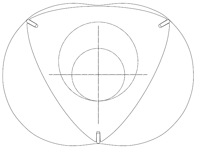
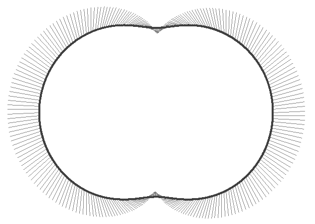
It is the “speed bump” on the apex real “road”, i.e. on the casing:

Image

Image

Look at the “speed bump” at lower and top side of the casing and at the “reverse” centrifugal force the apex seal experiences each time it passes from the area between the two spark plugs (or from the anti-diametrically from the spark plugs area).

Did you ever pass over a “speed bump” with, say, 50mph (80Km/h)?
Did the car take off the road?

The Wankel RX-8 requires strong springs under the apex seals, otherwise each apex seal will take off the epitrochoid twice per revolution around the casing.

Think of the difference in the PatWankel wherein the inner body rotates at constant speed about a fixed axis and the outer body rotates at constant speed about is own fixed axis, which means constant amplitude of the centrifugal acceleration. There are no "speed bumps" at all. The seals and the working surface have a, by far, easier life (reliability)


So, focus on the substantial / structural / geometrical problems of the rotary engine design and leave aside the tuning and the acoustic waves.

Even if the Wankel (or the PatWankel) could not breath as efficiently as a reciprocating piston engine with Bishop cylinder head, the small volume and weight of the rotary makes it superior for various applications (provided it is reliable and fuel efficient and emissions compliant).


You also write:
“When is a larger flame kernel a weakness? How many 2-stroke engineers design their flame kernel size ?”

The multi spark plug was known from the time of Ricardo.
Every engine maker manufactured and tested twin-spark engines.
How many engines use twin-sparks today?

As for the size of the 2-stroke cylinders, the Evinrude E-TEC (see the photo in a previous post and how similar is the "combustion cavity" with that of the PatRoVa) has 86mm bore x 78.7stroke, and a single spark plug per cylinder.

Bishop was superior from the rest F1 engines and FIA changed the rules to ban the rotary valve engines (and the rotary engines) from F1.

Disappointedly, the Bishop team having the experience from their F1 project, the funds, the know-how, the reputation etc failed to put anything in production.

It seems their design (which is actually a version of the Cross rotary valve with unclear differences from it: all you have to do is to read their patents and focus on the “characterizing portion” of the independent claims) is not good for normal use.

They modified a Honda CRF-450 to Bishop rotary, and according their tests (I still didn’t see a dyno) it was by far superior.

And as I know, around the CRF450 there are numerous “aftermarket” makers around the world.
You can find everything: improved pistons for extreme revs, improved connecting rods, improved cylinders, improved crankshaft, etc.

If the Bishop CRF450 cylinder head is so superior, shouldn’t the Bishop team put it in small production? Or give the license to an aftermarket firm to built and sell it?


What I think is that significant issues of the Bishop rotary valve remain still not addressed.
The problems in mass production / emission compliant engines and in F1 engines are quite different.

And it seems the lubrication is the biggest issue for the Bishop rotary valve.
With the openings of the Bishop rotary valve passing over the seals of the rotary valve, the lubrication cannot help being a “total loss” as in the Wankel.

The theories about carbon/graphite particles lubricating the contact between the seals and the rotary valve periphery are not persuasive. If this was the case, this different way of lubrication would be adopted in many other applications.

There are other issues, too, but the lubrication (which is equivalent to reliability) is the worst of all.


In comparison the PatRoVa rotary valve is based on the absence of loads on the sealing surfaces, which means dry operation (i.e. no need for lubricant in the cylinder head, yet actually zero mechanical friction in the cylinder head).

According the previously mentioned ASME paper, a 650cc Wankel chamber leaks like having a 1.5mm2 to 2mm2 orifice. However it operates even at low revs (say, 2,000rpm). If you follow a chamber of a Wankel RX-8 operating at 2,000rpm, it is equivalent (as regards the time provided to the compressed gas to leak) with a 650cc reciprocating piston engine running at 1,350 rpm (2,000*2/3).
Compare with the case wherein in a Ducati Panigale 1299 (650cc per cylinder) the desmodromic cylinder heads are replaced by PatRoVa cylinder heads:

Image

Above, say, 5,000rpm the overall gas leakage from the “dry” PatRoVa rotary valve is several times less than the leakage in a “decent” Wankel RX-8 operating at low-medium revs as above.
At lower revs, say below 2,000rpm (wherein a Panigale will never run, especially at full load), the leakage from the dry PatRoVa rotary valve is still less than the leakage in the RX-8 at 2,000rpm.


So far it seems you did not understand the most important: only after solving the fundamental (geometrical, structural, reliability etc) problems of a mechanism, only then it is worth to focus on the details, on the optimization of the breathing, on the twin-spark advantages, etc, etc.

Even if the Bishop rotary valve has the, by far, best breathing “in the West”, or the fastest combustion rate, its basic problems leave no chance to put it in real use.
It is meaningless to deal with the optimization of the breathing, if the “mechanism” has significant issues to solve (like: lubrication / reliability / etc).

The PatRoVa rotary valve solves a fundamental problem of the rotary valves.
Which?
Read how the “Rotary Vale history” at http://www.douglas-self.com/MUSEUM/POWE ... alveIC.htm starts.

As for its flow capacity of the PatRoVa rotary valve relative to the Bishop rotary valve (wherein the increase of the rotary valve periphery and the decrease of the piston stroke results in higher speeds of the rotary valve seals than the piston ring seals), as explained in many posts the PatRoVa can utilize as big ports as you like.

How big?
So big, to allow the complete Bishop rotary valve to pass through them.

So, if the target is the peak power and nothing else, the PatRoVa can make more than the Bishop.
If you can’t see how, I can further explain.

Thanks
Manolis Pattakos

Muniix
Muniix
14
Joined: 29 Nov 2016, 13:29
Location: Sydney, Australia

Re: 2 stroke thread (with occasional F1 relevance!)

Post

manolis wrote:Hello Muniix

You write:
“Ok, when you say "bottom" you don't mean underside, as the pressure would be pushing it away from the underside and against the far-side edge, away from the combustion origin. So "Bottom" is not the best description, Maybe standardising on Under, Inner and Outer seal edges may be more descriptive. Consistancy is important, also a glossary one can refer to. Just a thought.”

Thanks.

The term "bottom" is confusing in some cases wherein the "flank away the working chamber" should be used.

On the other hand, when the term “bottom” is supported / explained by the description, the drawings and the animations (as at http://www.pattakon.com/pattakonPatWankel.htm), its meaning gets more than clear, even for the non-English speaking.

With the animations everybody on earth (either he/she is Chinese, or Japanese, or French, or Korean, or Aborigine) can understand what you want to say or show.

By the way, have you managed to see “stereoscopically” the stereoscopic animations?


You write:
“Doubling up on sealing will increase the total seal area, negatively effecting friction mean effective pressure FMEP.”

Think about it again.

On one hand it does not double the seal area (it just avoids the “apex” seals and their serious implications).

On the other hand the overall seal area can decrease because the chamber (see the last animation in this forum) gets almost round and not long as in a Wankel (wherein the one dimension of the “rectangle” chamber is only 80mm while the other dimension is about double; according Mazda in their future Wankels, the chamber will get even “longer” ).

Even if you was right and the sealing area doubles, even then the gain from the reduced leakage is so big that justifies it by far.

Imagine the situation: you compress a quantity of air in a chamber (providing mechanical energy) and then a part of the compressed gas leaks.
This happens in the existing rotary engines.
It is like operating a 650cc per cylinder reciprocating engine, with a 1.5 to 2 mm2 hole on each piston crown.


You also write:
“Your environment is very different it is 3d with infinetly different angles, not the perfect environment for preset tension to provide the initial seal force.”

Everything in nature is 3D.

Fortunately the working surface and the seals in the PatWankel are 3D.

The 2D Sealing Grid and the 2D Design of the Wankel was tried for half a century, several billions were invested and lost on it, several automakers bankrupted because of it, and now it is phased out.

The Wankel RX8 is worth for one thing: it confirms that a rotary engine has strong advantages over the reciprocating engines. The point is to “correct” its serious “gas leakage” and “inefficient combustion” issues.

As you correctly wrote, there are infinite different angles in the PatWankel. What you didn’t write is that there is not one point of discontinuity, there is not one infinite curvature, everything is smooth.

If you see the stereoscopic animation the relative with the machining of the working surface, you will see how easily and cheaply these “infinitely different angles” are created with a conventional lathe.
It is worth noting that the sealing issues on the rotary engine took decades and with multi millions of dollars per year of research and development to come up with various solutions that had various measures of success.

You ask for comment, I gave valuable comment from a serious look at potential issues, gained from knowledge in very similar environments and aware of the real issues involved. Build the thing and identify techniques to measure the frictional forces, you will need a method of measuring the forces being exerted on the seals from gas forces, first from motoring tests and a way of measuring the pumping volumes of the engine. This will highlight issues with pumping and sealing, which will need a way of measing the forces against all of the seal area a full 3d map will need to be generated to identify what is going on, SAW sensors will likey be the best solution, surface acoustic wave sensors that can be inserted under the seals at the bottom of the slots. This will not give the side ways thrust data thou, which could be very valuable at this point.

You have created a extremely complex environment for the seals to work in, to solve these complex issues some of which I have identified in this forum and the only reply observed is of the style of "but do you see how xyz is better".

For the genuine effort and thought put in, and as asked for in your text "Any thoughts" the reply is strange to say the least.
Talking about the Wankel, it is worth mentioning one of the worst problems the engineers of NSU and Mazda experienced several decades ago:

http://www.nbtraffic.com/wp-content/upl ... d_bump.jpg

Confused?
No it is not the speed bumps on the roads.
It is the “speed bump” on the apex real “road”, i.e. on the casing:

http://www.pattakon.com/PatWankel/PatWankel_iGR_10.gif

http://www.pattakon.com/PatWankel/Wanke ... ration.gif

Look at the “speed bump” at lower and top side of the casing and at the “reverse” centrifugal force the apex seal experiences each time it passes from the area between the two spark plugs (or from the anti-diametrically from the spark plugs area).

Did you ever pass over a “speed bump” with, say, 50mph (80Km/h)?
Did the car take off the road?

The Wankel RX-8 requires strong springs under the apex seals, otherwise each apex seal will take off the epitrochoid twice per revolution around the casing.

Think of the difference in the PatWankel wherein the inner body rotates at constant speed about a fixed axis and the outer body rotates at constant speed about is own fixed axis, which means constant amplitude of the centrifugal acceleration. There are no "speed bumps" at all. The seals and the working surface have a, by far, easier life (reliability)


So, focus on the substantial / structural / geometrical problems of the rotary engine design and leave aside the tuning and the acoustic waves.

Even if the Wankel (or the PatWankel) could not breath as efficiently as a reciprocating piston engine with Bishop cylinder head, the small volume and weight of the rotary makes it superior for various applications (provided it is reliable and fuel efficient and emissions compliant).


You also write:
“When is a larger flame kernel a weakness? How many 2-stroke engineers design their flame kernel size ?”

The multi spark plug was known from the time of Ricardo.
Every engine maker manufactured and tested twin-spark engines.
How many engines use twin-sparks today?
All the current Ducati Testastretta DS and DVVT engines use twin spark plugs because they increased power from 150 to 160 using 11% less fuel. This has been mentioned many times on this exact forum.
As for the size of the 2-stroke cylinders, the Evinrude E-TEC (see the photo in a previous post and how similar is the "combustion cavity" with that of the PatRoVa) has 86mm bore x 78.7stroke, and a single spark plug per cylinder.

Bishop was superior from the rest F1 engines and FIA changed the rules to ban the rotary valve engines (and the rotary engines) from F1.

Disappointedly, the Bishop team having the experience from their F1 project, the funds, the know-how, the reputation etc failed to put anything in production.

It seems their design (which is actually a version of the Cross rotary valve with unclear differences from it: all you have to do is to read their patents and focus on the “characterizing portion” of the independent claims) is not good for normal use.
No the bishop is completely different, if is very similar to the Watson rotary valve in New Zealand that started a few years later, just concidence, the bishop was done in secret pretty much up to 1989 when they went to the F1 engine suppliers, Watson didn't start in proper until after 1990.

The Cross had oil everywhere and didn't use bearings to support the valve, didn't allow the valve to operate with clearence.

They were two completely different approaches and the bishop and watson valves worked. Arthur Bishop used his world renown experience with rotary valves in his world leading variable ratio power steering to solve the issues with the rotary valve. The Cross never worked truely properly anywhere nearly as well. Bishop has been awarded the Safety invention of the year for Nascar recently, some 40 years after he patented it. They make the titanium steering components for several F1 teams.

The Bishop and Watson operated with no oil in the fuel (well Watson initially used premixed fuel through being conservative, but learned it was not needed through experimentation) and ran extensively with no observable wear on the seals, they operated with a coating of combustion products on the seal faces, even with 1000's of hours in bishops case over a twenty year period and over 50,000 kilometers for the Watson engine. It is the environment they operate in that bishop created for its seal array that allows this and their experience and the experience of the Watson rotary valve backs this up.

They both had design that worked, the latest sealing system developed by Bishop provide for very low crevice volumes, low blow-by where the only path was for it to be recycled into the next intake when pressure drew it back into the cylinder or it could be stored outboard and discarded or plumbed back into the airbox.

Bishop is a large private automotive business, they have a RnD budget of 5-15 million dollars yearly. One in five cars produced world wide has Bishop technology in it. Companies of this size need their developments to lead to sales of 10's of millions of dollars a year to justify, the bishop rotary valve was a pet project of Arthur Bishop, it was his private business and he alone could choose what RnD project got funding, when he died in July 2006 that obviously all changed, this would have been during the CRF-450 head development when it was also passed over for honda's own cbr600 engine denying it again a chance to prove itself in Moto2. This likely contributed to his death and it was all over, the engineers gave it their best, were obstructed at every attempt to show how good it was, and clearly it was not going to deliver a return on investment to even employ a store person or receptionist without successful demonstration in a racing environment. Endurance runs on dyno's only get you so far. It was all over the engineering staff left for other opportunities in other interesting developments, they were burned out.

Now 10 years on the climate has changed, it could well be time to give it another go, further developments by one of the gang developed Turbulent Jet Ignition which was awarded 'Automotive Innovation for 2016'. That was worth doing and TJI and the Bishop rotary valve are a pair of technologies that would work together brilliantly, one provides ultralean the other provides the air to operate at ultra lean. Ultra lean lowers temperatures and peak pressures assisting the valve provide the high volume of air.
They modified a Honda CRF-450 to Bishop rotary, and according their tests (I still didn’t see a dyno) it was by far superior.

And as I know, around the CRF450 there are numerous “aftermarket” makers around the world.
You can find everything: improved pistons for extreme revs, improved connecting rods, improved cylinders, improved crankshaft, etc.

If the Bishop CRF450 cylinder head is so superior, shouldn’t the Bishop team put it in small production? Or give the license to an aftermarket firm to built and sell it?


What I think is that significant issues of the Bishop rotary valve remain still not addressed.
The problems in mass production / emission compliant engines and in F1 engines are quite different.

And it seems the lubrication is the biggest issue for the Bishop rotary valve.
With the openings of the Bishop rotary valve passing over the seals of the rotary valve, the lubrication cannot help being a “total loss” as in the Wankel.

The theories about carbon/graphite particles lubricating the contact between the seals and the rotary valve periphery are not persuasive. If this was the case, this different way of lubrication would be adopted in many other applications.

There are other issues, too, but the lubrication (which is equivalent to reliability) is the worst of all.
You miss understand how the Bishop operates. The valve operated dry, there was no oil to cause emissions or lubrication issues as the bearing were sealed, the window leading edge in the valve through its motion, gently rose up to meet and support any radial inwards flexing of the axial seal(from the exhaust or inlet pressures acting on them at close time which is very low, being very rigid and cooled with coolant flowing past their slots on all three sides), you can see the extrusions that do this in the images.

The CRF-450 head development was a research head with lots of sensors engineered into it, not a unit designed for production for retail sale it was developed for Honda as part of the 4 stroke moto2 evaluation, Honda provided them with an engine to evaluate the results, it delivered as much power as the bottom end could take with the smallest valve they ever made. In order to make any money off of a CRF-450BRV retail head would take a multi million dollar initial order for a thousand units to meet minimum viable production quantity to justify a production run, they would then need to employ all the staff needed to support this and that would cost many millions of dollars per year. It just wasn't commercially viable, it would be taking money away from other developments. Bishop was a business with a balance sheet and profit loss statements, this is the real world. What someone thinks and what is good business may not be the same.

The bishop worked and so did the Watson rotary valve, with no oil in the fuel, and Watson's observations over 50,000 kilometres may be contra to your beliefs, the facts and evidence are what count. The seals operated with a layer of carbon on them and they experienced no measureable wear over 50,000 kilometers/30,000 miles.

Whereas the issues identified with the PatRoVa the fluid flow issues, it has sealing issues related to cylinder pressure and gasses leaking into the valve area. The Bishop valve flow coefficient was optimised over time, and improved around 50% during development, it has a natural flow that provides tumble or dual cross tumble without taking energy from the flow to produce. All the fundamentals were on the right path from the get go. Even pressure wave action can be tuned in by window geometry, and scavenging observed to be more than twice as effective as poppet valves requiring only half or less degrees to achieve superior scavenging from 96-99.5% far better than the 60-96% of the best 4 valve poppet valve engines.
In comparison the PatRoVa rotary valve is based on the absence of loads on the sealing surfaces, which means dry operation (i.e. no need for lubricant in the cylinder head, yet actually zero mechanical friction in the cylinder head).
The bishop operates dry also, only the bearings have lubrication pumped through them, to reduce the friction, the oil is sealed into the bearings. This is the same approach as the Watson rotary valve design.
Whereas as identified the PatRoVa has very poor air pumping and flow rate, a very complicated flow path (lots of turns, change of direction all consuming flow energy, resulting in flow seperations, where flow inertial energy is working against etc), that flow inertia is working against. Two flows that are flowing into one another(pressure effects flow), it has terrible mechanical fluid flow issues, ones that are fundamentally unworkable and can't be improved without changing the laws of physics.
According the previously mentioned ASME paper, a 650cc Wankel chamber leaks like having a 1.5mm2 to 2mm2 orifice. However it operates even at low revs (say, 2,000rpm). If you follow a chamber of a Wankel RX-8 operating at 2,000rpm, it is equivalent (as regards the time provided to the compressed gas to leak) with a 650cc reciprocating piston engine running at 1,350 rpm (2,000*2/3).
Compare with the case wherein in a Ducati Panigale 1299 (650cc per cylinder) the desmodromic cylinder heads are replaced by PatRoVa cylinder heads:

http://www.pattakon.com/PatRoVa/PatRoVa_Panigale.jpg

Above, say, 5,000rpm the overall gas leakage from the “dry” PatRoVa rotary valve is several times less than the leakage in a “decent” Wankel RX-8 operating at low-medium revs as above.
At lower revs, say below 2,000rpm (wherein a Panigale will never run, especially at full load), the leakage from the dry PatRoVa rotary valve is still less than the leakage in the RX-8 at 2,000rpm.
The most significant point where leakage happens is during the compression and power strokes, where the pressure is high, not during the periods of low cylinder pressures!! Showing the exhaust at fully open doesn't show anything meaningfull information on its sealing.
only after solving the fundamental (geometrical, structural, reliability etc) problems of a mechanism, only then it is worth to focus on the details, on the optimization of the breathing, on the twin-spark advantages, etc, etc.

Even if the Bishop rotary valve has the, by far, best breathing “in the West”, or the fastest combustion rate, its basic problems leave no chance to put it in real use.
It is meaningless to deal with the optimization of the breathing, if the “mechanism” has significant issues to solve (like: lubrication / reliability / etc).

The PatRoVa rotary valve solves a fundamental problem of the rotary valves.
Which?
Read how the “Rotary Vale history” at http://www.douglas-self.com/MUSEUM/POWE ... alveIC.htm starts.

As for its flow capacity of the PatRoVa rotary valve relative to the Bishop rotary valve (wherein the increase of the rotary valve periphery and the decrease of the piston stroke results in higher speeds of the rotary valve seals than the piston ring seals), as explained in many posts the PatRoVa can utilize as big ports as you like.
Clearly you didn't undestant my reply to the operation of the bishop valve and how it handles it normal operating environment. So here it is again, The piston rings are lubricated by a thin film of oil. However, due to the very low magnitude of sliding speed around the top dead center position (TDC), piston rings do not “hydroplane” on the oil film as they do at mid stroke in the cylinder. Consequently, metallic contact at TDC creates wear, and increases friction coefficient very significantly. While the Bishop valve is rotating in its fully lubricated bearings with relatively constant angular velocity at at very low friction levels the environment it is designed for.

The peripheral speed of the seals of the bishop is proportional to the mean piston speed and the identified valve size (typically 60-75% of bore size), as they are rotating at half engine speed and in only one direction this is not an issue, until you get into really huge cylinders far larger than 127mm bore along with very high engine speeds, and as far as scaleing to cylinder size it is so far superior to the PatRoVa due it its superior flow coefficent. Here small size is what matters, one needs to identify size and flow requirements through simulation.
How big?
So big, to allow the complete Bishop rotary valve to pass through them.

So, if the target is the peak power and nothing else, the PatRoVa can make more than the Bishop.
If you can’t see how, I can further explain.
I don't see how having a super large head, which buy the way wouldn't work due to the limitations that the valve windows have to be contained in the compression chamber which is limited by geometry constraints of that volume. Anyway what ever floats ones boat.
Last edited by Muniix on 13 Feb 2017, 14:33, edited 3 times in total.

J.A.W.
J.A.W.
109
Joined: 01 Sep 2014, 05:10
Location: Altair IV.

Re: 2 stroke thread (with occasional F1 relevance!)

Post

Munix, do try to edit out the needlessly emotive non-technical language,
it presents here as infantile, & tends to debase your credibility, accordingly.

I'd also note that this thread has strayed off the 2T topic basis lately,
although having noted that, I also note that Ducati have now gone to a V4 1000cc design
for Superbike Racing homologation, after failing to get the desired race winning results with
their traditional L-twin, even in extreme bore/stroke 'Panagale' form - & with a capacity advantage..
"Well, we knocked the bastard off!"

Ed Hilary on being 1st to top Mt Everest,
(& 1st to do a surface traverse across Antarctica,
in good Kiwi style - riding a Massey Ferguson farm
tractor - with a few extemporised mod's to hack the task).

Muniix
Muniix
14
Joined: 29 Nov 2016, 13:29
Location: Sydney, Australia

Re: 2 stroke thread (with occasional F1 relevance!)

Post

J.A.W. wrote:Munix, do try to edit out the needlessly emotive non-technical language,
it presents here as infantile, & tends to debase your credibility, accordingly.

I'd also note that this thread has strayed off the 2T topic basis lately,
although having noted that, I also note that Ducati have now gone to a V4 1000cc design
for Superbike Racing homologation, after failing to get the desired race winning results with
their traditional L-twin, even in extreme bore/stroke 'Panagale' form - & with a capacity advantage..
My thoughts exactly on the valve, sealing discussion, I have fixed this up now I believe, is more analytical and technical.

A 30+ year career using load testing and simulation to test vendor claims and when they've failed normally they are happy to find out, rarely have I experienced irrationality, and then one has to push back hard on those claims, especially when they are repeated. People need to be educated so they can make accurate decisions, that was my Intent.

The Ducati superbike actually did pretty well in the last rounds, on the podium frequently if not winning. The factory Ducati squad heads into the new season with strong momentum after Davies stormed to seven wins from the final eight races in 2016. They have not said anything about when a V4may be produced, just that they would like to capitalise on their MotoGP efforts, sounds good at board meetings and investor reports. They have said that the V2 is to be raced for 2017/18. They have pushed the V-twin beyond what it was ever thought possible, thou all the superbikes are gobbling air and fuel at a rate and levels that produce well over 1,000 hp of heat energy, that is an insane figure when you think about it. The Ducati is more economical with fuel.

No wonder electric vehicle racing is taking off. We need to come up with ways to put liquid/gaseous fuels into contention again. I was thinking exactly this, and was wanting to steer the conversion that way for the past week. When electric vehicles have a near perfect torsional torque and don't have to be designed for economy or performance they can be both at the same time. They are througing down a challenge for ICE to respond to.

With the new Tesla racing class vehicle achieving 0-100 kph in 2.1 seconds, now that is insane, not even F1 can do that and in a body that can seat 5 adults and two children and still have two boots, that is damn impressive.

My ideas were along the lines of finding a more efficient crank train, with all the recent research interest in offset cranks and gudgens pins. If we can find ways of putting more energy into a single engine cycle and make it as efficient as possible extracting all the work feasible will help, the torsional variance over the intake/compression/power/exhaust cycle so that we minimise the losses over a single cycle but increase the power inputs and outputs.

This is what interests me at the moment, clearly research shows that larger cylinders have better volume surface ratio's that assist thermodynamic efficiency. So the move by Ducati to more and smaller cylinders is kinda counter intuitive, more frictional area and more thermal losses,will take them down to the efficiencies of the 4 cylinders. Doesn't make sense at all.

Maybe by using a torque filling and damping using mild hybridisation storing power electrically and super efficient combustion.

Any Ideas ?
Last edited by Muniix on 13 Feb 2017, 16:13, edited 1 time in total.

manolis
manolis
107
Joined: 18 Mar 2014, 10:00

Re: 2 stroke thread (with occasional F1 relevance!)

Post

Hello Muniix.

Quote from http://ralphwatson.scienceontheweb.net/rotary.html (wherein Ralph Watson himself writes about his rotary valve)

“Already knowing something of the engines of Ronald CROSS, which used rotary valves, research commenced at the Auckland University engineering library and a paper was found which he had read to the Institute of Engineers in England in 1935.

CROSS had adapted many engines to rotary valves and had designed several more during the period between the first and second world wars. Several of these were conversions of Rudge motorcycle engines and therefore I made contact with a local enthusiast who was restoring Rudge motorcycles, Mr Norman Maddock. He was most helpful and provided me with road test data covering motorcycles converted by CROSS.
. . .
During the two decades between the wars Ronald CROSS undertook considerable development work involving rotary valves, making or converting approximately sixteen engines. These engines incorporated a cylindrical valve rotating at right angles to the cylinder bores and usually running parallel with the crankshaft. However in some in line engines, including a six cylinder Austin conversion, valves were arranged across the cylinder block and this required a complicated gear drive.

In order to achieve a satisfactory seal, it was necessary to have the cylindrical valves closely fitting in their housings and under pressure. Friction was therefore a problem and an oil supply had to be provided as with crankshaft bearings. In this regard CROSS made what he regarded as a breakthrough in design, around about 1934.

He used a floating cylinder which kept pressure on the valve and against the head, this being fixed solidly to the crankcase. It was necessary to provide for only a very small degree of cylinder movement. A clever system of levers held and controlled the pressure to the minimum required to form a seal. Pressure was applied to the closed top of the valve, as well as the ported underside and the area of friction was approximately three times greater than necessary.

An interesting and informative book was published in 1946, written by Marcus C. Inman Hunter, a copy of which I had been able to obtain on loan. This book included an analysis of the desirable features which should be included in the design of a rotary valve. I added my own ideas to the equation and gave considerable thought to all possibilities, in order to decide on a design which would not inherit the limitations of earlier efforts. A cylindrical valve positioned across the top of the cylinder appeared to me the best approach. This arrangement offers several possible variations.
One of which I will call the CROSS type, after the original designer Ronald CROSS already mentioned. This has separate curved inlet and exhaust passages, which overlap and pass each other to enter and exit at each end of the rotating valve.
. . .

The CROSS type arrangement formed the basis of my rotary valve design, but with specific modifications so as to include the following features: -

A cylindrical valve running on ball or roller bearings, with clearance between the valve and housing.

A freely moving port seal, maintained in contact with the rotating valve by gas pressure in the cylinder. I had in mind the effective sealing achieved in respect of piston rings, where gas pressure from behind expands the ring during compression and power strokes. It was appreciated that auxiliary springs would have to be provided to maintain pressure on the seal during exhaust and inlet strokes, as a piston ring in itself provides the spring pressure required.

Port seal and rotary valve to be made from compatible materials, which will run together without wear.

Image

Provision for the lubrication of the valve and seal, with the utilisation of the lubricating oil as a means of cooling the valve assembly. However it was presumed that the close proximity of the inlet and exhaust passages in the CROSS type valve, would be advantageous in respect of temperature control.”

End of Quote


Count how many times Watson mentions Cross in the above quote.


In response to my:
“It seems their design (which is actually a version of the Cross rotary valve with unclear differences from it: all you have to do is to read their patents and focus on the “characterizing portion” of the independent claims) is not good for normal use.”

You write:
“No the bishop is completely different, if is very similar to the Watson rotary valve in New Zealand that started a few years later, just concidence, the bishop was done in secret pretty much up to 1989 when they went to the F1 engine suppliers, Watson didn't start in proper until after 1990.”

What you say is that Bishop is completely different than Cross rotary valve, and very similar to Watson rotary valve.

However Watson himself considers his rotary valve as “a modification of the Cross rotary valve”.

Either I miss something or you can not see the similarities.

It would help if you could write down the unique characteristics of the Bishop rotary valve (say, as in an independent claim of a patent).


You also write:
“and what is the reply to all the acoustic/thermal/pressure issues of the sealing arrray, is below”

The reply is more than simple: first deal with the basic / fundamental problems / issues of a mechanism and them optimize it.
You start the opposite way.


Let’s suppose your claim about the CRF450 Bishop is correct, i.e. it was ready for mass production.

Most (if not all) of Bishop patents have expired / cease. It doesn’t matter why.

So, start making the CRF450Bishop and sell it.
And give some fair royalties to Bishop’s inheritors.
Everybody will be happy.
The market needs such a product, provided it is affordable and without reliability issues.
It will be an instant success.
Making a desmodromic cylinder head (like Ducati’s) seems a nightmare as compared to making a Bishop rotary valve cylinder head.


You also write:
“All the current Ducati Testastretta DS and DVVT engines use twin spark plugs because they increased power from 150 to 160 using 11% less fuel. This has been mentioned many times on this exact forum.”

However, the Ducati Panigale with a single spark plug per cylinder (and without DVVT) makes 20% more power from the same capacity.

As I explained again, if the twin spark was so good, the modern big-diameter 2-strokes (Evinrude G2 E-TEC, Rotax 850 E-TEC etc) would use it. But they don’t.


You also write:
“Blah, Blah get over it, the bishop worked and so did the Watson rotary valve, with no oil in the fuel, and Watson's observations over 50,000 kilometres are contra to your beliefs, which don't count, the facts and evidence do. The seals operated with a layer of carbon on them and they experienced no measureable wear over 50,000 kilometers/30,000 miles.”

I told you again: You loose nothing to be polite. You have your arguments. I have mine. Respect it, or talk alone.

As for the “dry lubrication” of the Bishop rotary valve, there is no such lubrication.
It would be great if this was the case.
If you leave two dry and heavily loaded surfaces to rump each other (as the surface of the Bishop rotary valve and the seals of the Bishop rotary valve), they will soon wear.
If not, the world of engines turns “upside-down”.

Explain to the rest forum members why this “magical” way of lubrication is not applicable to the piston skirt, too, or to the piston rings.

I still didn’t see a plot of the famous CRF450Bishop you are talking.

As for the “data” regarding the longevity of the Bishop and Watson rotary valves, let me remind you that only in the hands of an independent third party (preferably a customer who paid to buy it and requires / demands, among others, reliability at all conditions).

Simpleminded question:
You sound more than confident about the superiority of the Bishop rotary valve over all other valves.
So, why haven’t you modified your motorcycle or car to Bishop rotary valve?
It doesn’t need millions of dollars to make a prototype.
You do not need to make it at “mass production quality”. Just to operate reliably to show it superiority. Then you will drive a unique car or motorcycle. You can’t imagine how it is.

Until now you talk about what you heard from others.
What Ralf Watson said about the lubricant consumption of his prototype Rotary Valve Engine.
What Bishop saw in the dyno.
Were you there in the oil changes or in the repairs of the rotary valve?
Have you a dyno plot of the Honda-CRF450-Bishop to show?
With a prototype in your hands things get completely different.
Do try it.

See for instance the Honda Civic B16A2 VTEC modified to pattakon VVA-roller at http://www.pattakon.com/pattakonRoller.htm .
Or several other prototype engines presented in the http://www.pattakon.com web site.

Simulations are something, but they are nothing as compared to the real thing.


As I wrote in previous posts, the LiquidPiston engine has the support of the MIT, of the DARPA (3.5 millions so far) and of the Shikorsky.

When you dig deeper in their architecture, you find things they, probably, do not yet know.

Quote from http://www.pattakon.com/pattakonPatWankel.htm

In the following LiquidPiston rotary engine (or alternatively: in the following section of a PatWankel wherein the working surface is in the inner body and wherein the outer body is immovable) :

Image

they are required two eccentric-shaft-rotations for three combustions (one per working chamber).

The synchronizing gearwheels are heavily loaded during each combustion. This causes wear, noise, friction, "play" of the rotor, need for bigger gaps (and so more gas leakage) between the side seals and the peak seals, need for better lubrication of the gearwheels, etc.
Every time the rotor passes from a combustion TDC (it happens 1.5 times per eccentric shaft rotation), the load on the teeth of the inner gearwheel changes direction; the inevitable backlash is a problem (impact loads, noise, wear etc)

The bearing of the rotor "runs" at 50% higher r.p.m than the eccentric shaft.

The force on the rotor bearing is substantially heavier than the force the high pressure gas applies onto the rotor during the compression / combustion / expansion. The "super-over-square" design causes a heavy force onto the rotor, and an even heavier force onto the fast revving rotor bearing.

There is an extra load on the rotor bearing (also in a continues basis, because every combustion causes this loading) by a strong pair-of-forces caused by the side location of the heavily-loaded synchronizing gearwheels. Due to this pair-of-forces, the side-walls of the rotor stop being exactly parallel to the side-walls of the casing: the seals suffer and the gas leakage increases.”

In comparison, the following PatWankel:

Image

they are required three rotations of the power shaft (which is secured on the inner body) for three combustions (one per working chamber).
As in the Wankel, the synchronizing gearwheels are not loaded by the combustion.

End of Quote


Thanks
Manolis Pattako